Group assignment: Output Devices
During the Output Devices week, our team focused on power management and consumption analysis. We tested a wide range of actuators to understand their electrical requirements and efficiency.
Technical analysis:
- Power Consumption: We measured voltage and current for DC motors, servos, steppers, buzzers, and Neopixel rings to calculate their real-wattage using the power formula (P=V*I).
- Safety Protocols: We documented critical safety measures, such as using flyback diodes for inductive loads and external drivers for high-current devices.
- Dynamic Testing: Using potentiometers and PWM signals, we observed how power usage fluctuates based on motor speed, LED brightness, and buzzer frequency.
Output devices - Assignment:
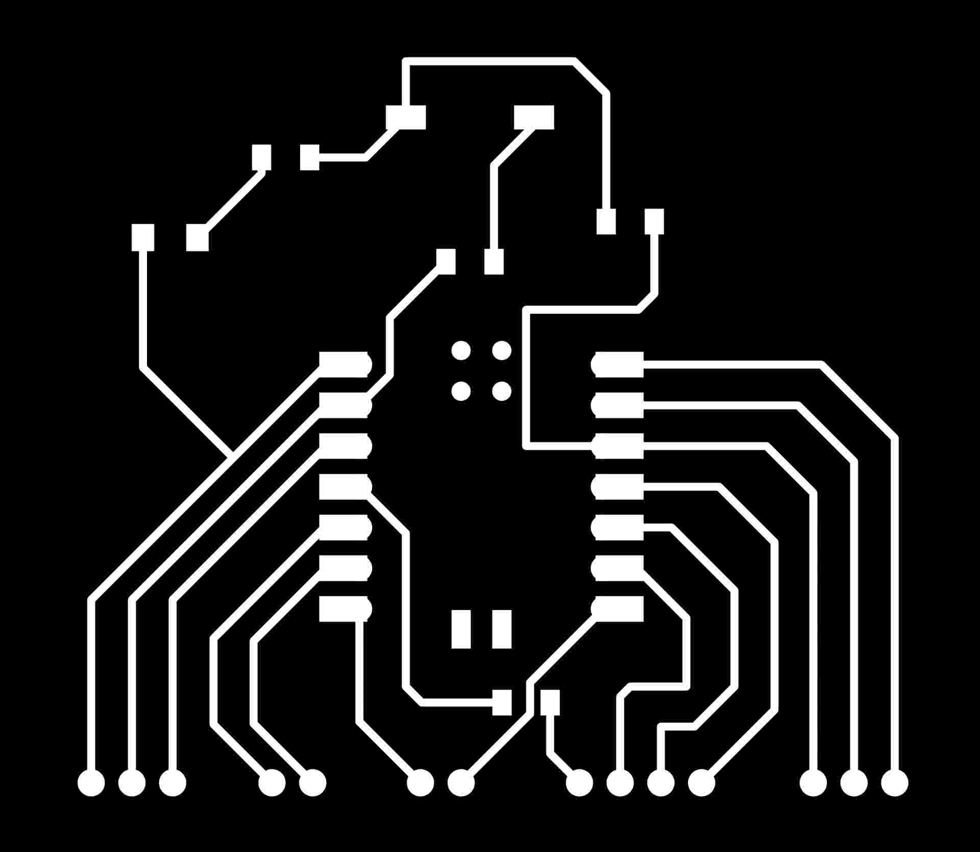
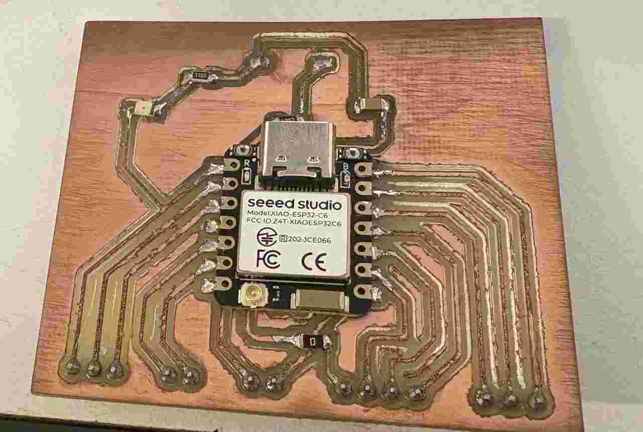
For this week's assignment, the primary objective was to implement and control external output devices, specifically a DC motor and an OLED screen. However, before beginning the integration, I had to completely redesign the PCB from scratch. My previous board had two critical limitations that made it unsuitable for this phase: first, the hardware I²C pins were mismatched, which forced me to use bit-banging for the inputs; and second, the design lacked external breakout pins, making it physically impossible to connect new output components. Consequently, I developed a new, more versatile board that corrects the routing errors and provides the necessary headers to interface with multiple peripherals simultaneously, opting for a cleaner, more robust layout.
At a fundamental level, output devices are controlled through digital signals that typically operate in two discrete states: HIGH, representing the maximum voltage level (3.3V on the XIAO RP2350), and LOW, representing 0V. While these binary states are perfect for simple operations like toggling an LED, many components require a way to receive varying amounts of power. This is achieved through Pulse Width Modulation (PWM), a technique that effectively simulates an analog-like behavior by rapidly switching a digital signal between its HIGH and LOW states. The efficiency of this power delivery is governed by the Duty Cycle, which is the percentage of time the signal remains in the HIGH state during one complete cycle. A 100% duty cycle means constant voltage, while a 50% cycle provides power only half of the time, resulting in an average voltage that allows for precise control of the connected hardware.
By mastering these two methods—direct digital signaling and pulse modulation—the microcontroller can interact with a wide range of peripherals. In this project, digital communication is used to send complex data to the OLED display, while the PWM technique is utilized to regulate the power sent to the DC motor. This combination demonstrates how a single microcontroller can manage both high-speed data protocols and variable power distribution simultaneously. The transition to this new board architecture was essential, as it transformed the system from a restricted input-only device into a flexible platform capable of driving multiple outputs and providing real-time physical and visual feedback.
DC Motor Control & Driver Board
A DC Motor is a device that converts electrical energy into mechanical rotation. At its simplest level, it works through electromagnetism: when electricity flows through the internal coils, they become temporary magnets. These magnets push against permanent magnets inside the motor casing, and that magnetic "push" is what makes the shaft spin. The more power we provide, the faster and stronger it rotates.
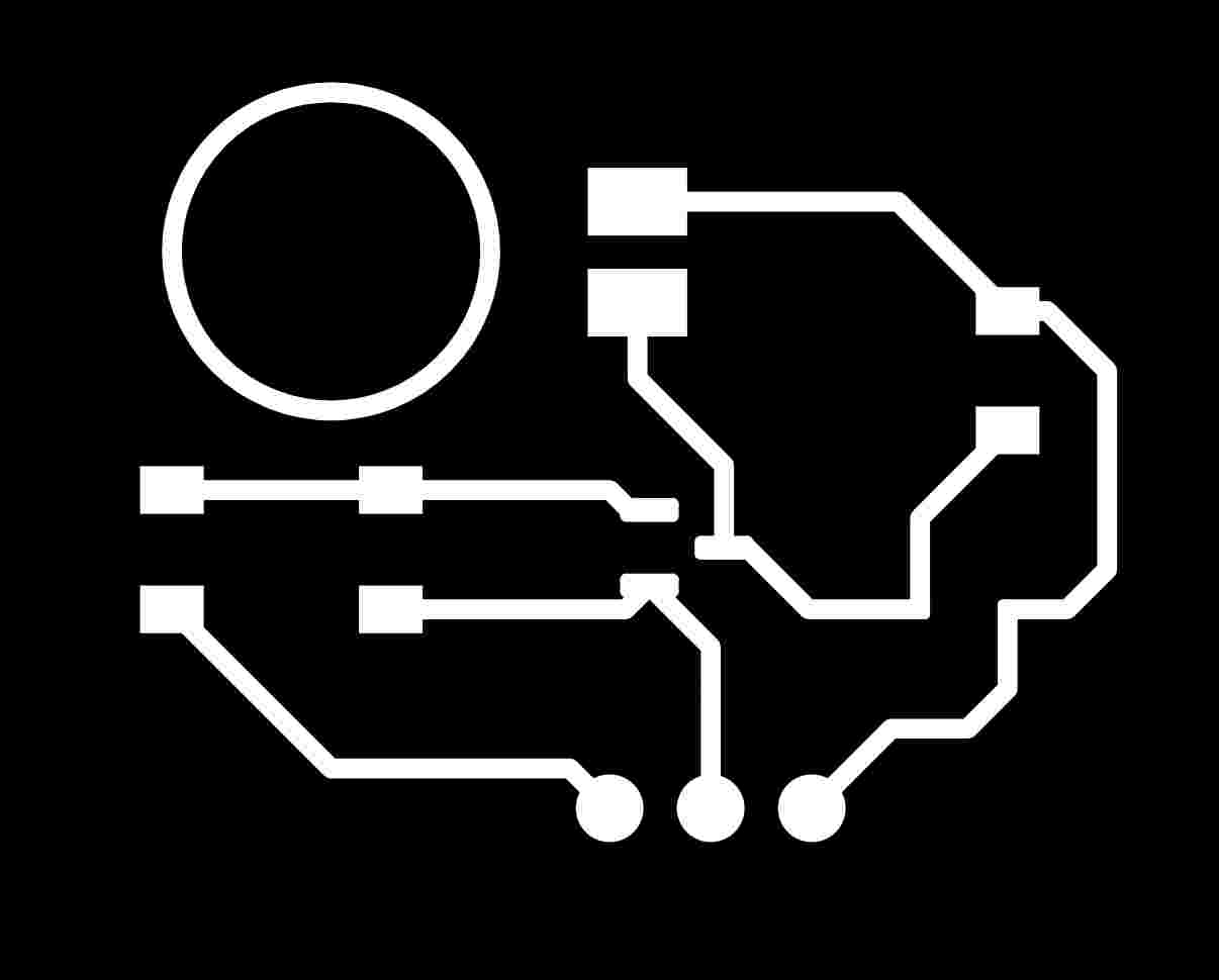
While the XIAO RP2350 is the "brain" of the project, it is not strong enough to power a motor directly. Microcontrollers can only provide a tiny amount of current, and a motor needs a lot more to start spinning. To solve this, I designed a custom driver board that acts as a bridge. This board uses a small signal from the brain to control a large amount of power from a battery or power supply, ensuring the microcontroller remains safe while the motor does the heavy lifting.
Bill of Materials (BOM)
| RefDes | Qty | Value / Type | Footprint | Description |
|---|---|---|---|---|
| Q1 | 1 | BC817 (NPN) | SOT-23 (SMD) | Transistor switch for motor power. |
| D1 | 1 | BAT54J (Schottky) | SOD-323 (SMD) | Flyback diode for inductive protection. |
| R1, R2 | 2 | 1k / 10k Ω | 1206 (SMD) | Base limit and Pull-down resistors. |
| C1 | 1 | 10uF / 100nF | 1206 (SMD) | Decoupling capacitor for noise filtering. |
| J1, J2 | 2 | Pin Headers | 2.54mm Pitch | Input (Signal) and Output (Motor) connectors. |
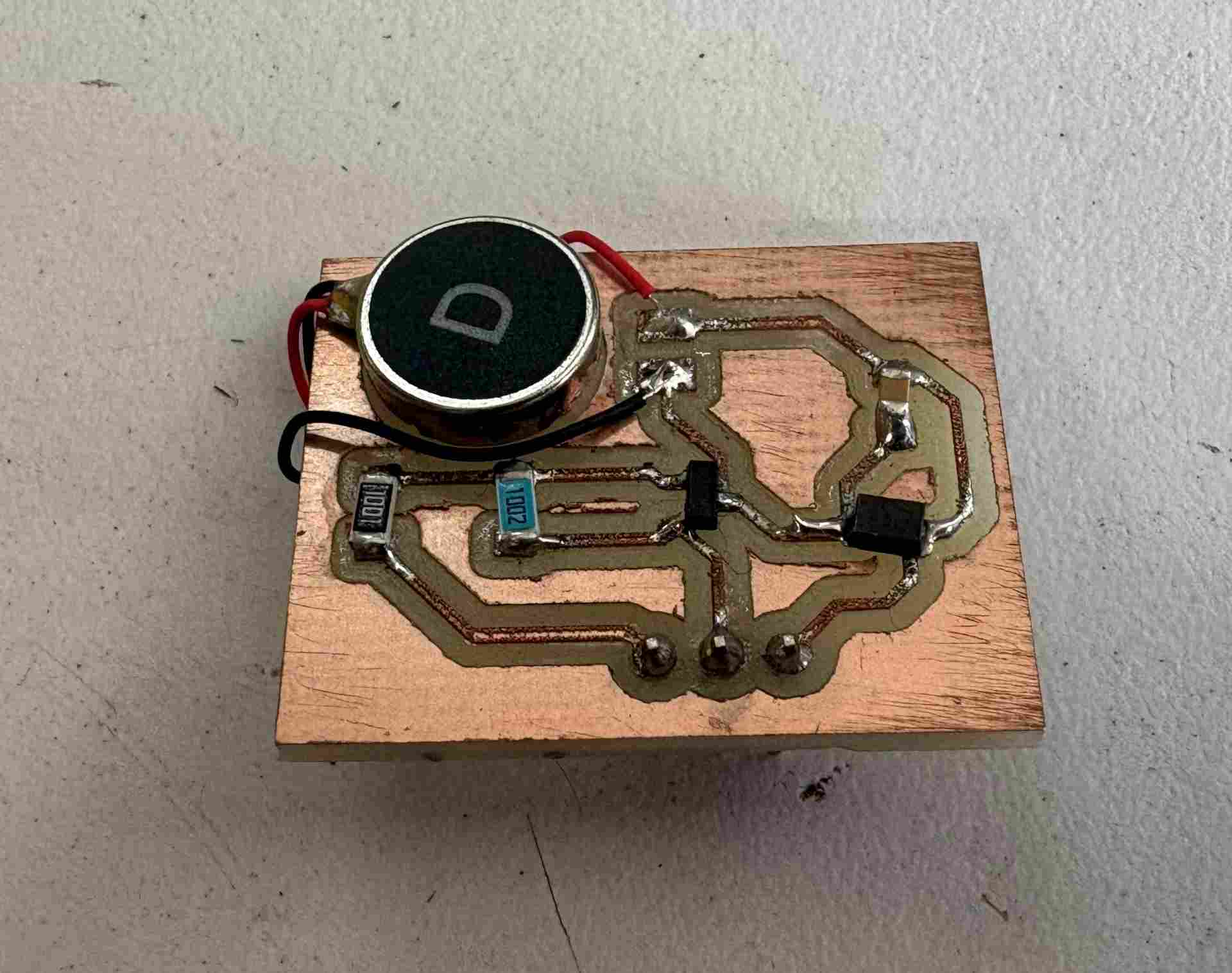
The physical integration of the DC motor driver was completed by fabricating a custom PCB. This ensured robust power management for the motor’s current draw and consolidated the connection to the XIAO ESP32C6. The following image shows the fully soldered board, featuring clean joints and a compact layout designed for the final project.
Serial Control Implementation
For the DC motor operation, I developed a firmware routine that enables real-time control through the
Serial Monitor. In this setup, the microcontroller acts as a command interpreter for
incoming serial data: when the user inputs a value of 1, the program sets the assigned
output pin to HIGH, triggering the motor's activation. Conversely, sending a 0
commands the pin to LOW, immediately cutting power to the actuator.
    const int MOTOR_PIN = 1;

    void setup() {
    pinMode(MOTOR_PIN, OUTPUT);
    Serial.begin(115200);
    Serial.println("Send '1' for FULL POWER or '0' to TURN OFF");
    }

    void loop() {
    if (Serial.available() > 0) {
        char input = Serial.read();

        if (input == '1') {
        digitalWrite(MOTOR_PIN, HIGH); // Output 100% duty cycle
        Serial.println("Motor at full power!");
        }
        else if (input == '0') {
        digitalWrite(MOTOR_PIN, LOW);
        Serial.println("Motor stopped");
        }
    }
    }
This implementation provides a highly efficient and interactive method for hardware debugging. By utilizing software-based triggers, I was able to validate the motor's response and the driver circuit's stability without the need for additional physical components like switches or buttons, streamlining the testing phase of the project.
The following video demonstrates the DC motor's performance and responsiveness. By sending commands through the Serial Monitor, I verified that the XIAO correctly toggles the power state. When '1' is sent, the motor activates at full speed, and it stops immediately upon receiving '0', confirming the reliability of the control circuit and the firmware logic.
During this week, I worked with output devices by integrating a vibration motor and an OLED display using the XIAO microcontroller. I controlled the vibration motor to generate haptic feedback and used I2C communication to display information on the OLED screen.
By reusing my previous PCB, I focused on properly managing connections, power requirements, and programming both outputs to work reliably. This process helped me understand how to combine different types of outputs—visual and tactile—to create more interactive systems. Overall, this week strengthened my ability to translate digital signals into both physical feedback and visual information, which is highly relevant for my wearable project.
Files
├── Week10MotorPCB
│   ├── week10.kicad_pcb
│   ├── week10.kicad_pro
│   ├── week10.kicad_sch
│   ├── Cuts
│   │   ├── drills_top_layer_1.png.rml
│   │   ├── outline_top_layer_2.png.rml
│   │   └── traces_top_layer_0.png.rml
│   ├── Gerber
│   │   ├── week10-B_Cu.gbr
│   │   ├── week10-B_Mask.gbr
│   │   ├── week10-B_Paste.gbr
│   │   ├── week10-B_Silkscreen.gbr
│   │   ├── week10-Edge_Cuts.gbr
│   │   ├── week10-F_Cu.gbr
│   │   ├── week10-F_Mask.gbr
│   │   ├── week10-F_Paste.gbr
│   │   ├── week10-F_Silkscreen.gbr
│   │   ├── week10-job.gbrjob
│   │   ├── week10-NPTH.drl
│   │   └── week10-PTH.drl
│   └── Png
│       ├── drills_top_layer_1.png
│       ├── outline_top_layer_2.png
│       └── traces_top_layer_0.png
└── Week10XiaoPCB
    ├── Week10.1.kicad_pcb
    ├── Week10.1.kicad_pro
    ├── Week10.1.kicad_sch
    ├── Cuts
    │   ├── drills_top_layer_0.png.rml
    │   ├── outline_top_layer_2.png.rml
    │   └── traces_top_layer_1.png.rml
    ├── Gerber
    │   ├── Week10.1-B_Cu.gbr
    │   ├── Week10.1-B_Mask.gbr
    │   ├── Week10.1-B_Paste.gbr
    │   ├── Week10.1-B_Silkscreen.gbr
    │   ├── Week10.1-Edge_Cuts.gbr
    │   ├── Week10.1-F_Cu.gbr
    │   ├── Week10.1-F_Mask.gbr
    │   ├── Week10.1-F_Paste.gbr
    │   ├── Week10.1-F_Silkscreen.gbr
    │   ├── Week10.1-job.gbrjob
    │   ├── Week10.1-NPTH.drl
    │   └── Week10.1-PTH.drl
    └── Png
        ├── drills_top_layer_0.png
        ├── outline_top_layer_2.png
        └── traces_top_layer_1.png