Group assignment: Input Devices
In this group assignment, we explored the fundamentals of Input Devices by analyzing how sensors translate environmental changes into electrical signals. We focused on measuring and comparing analog vs. digital signals using specialized laboratory equipment.
Learning outcomes:
- Signal Probing: We used a multimeter and an oscilloscope to visualize real-time data from sensors like accelerometers, photoresistors, and motion sensors.
- Protocol Analysis: We verified the I2C communication protocol, understanding how data is structured and synchronized between sensors and microcontrollers.
- Calibration: We learned to interpret oscilloscope waveforms to identify noise and signal stability in different input components.
Input devices - Assignment:
The objective this week was to integrate a single data input method using the Seeed Studio XIAO RP2350. This assignment focused on capturing motion data through a digital sensor module, specifically the MPU6050, which allows for a sophisticated understanding of physical movement. Digital sensors like the MPU6050 communicate using structured protocols such as I²C, sending organized data packets instead of the continuous, often noisy voltage signals associated with analog components. This combined accelerometer and gyroscope module provides a comprehensive data set across three axes for both acceleration and angular velocity, making it a versatile choice for motion-tracking applications.
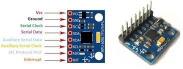
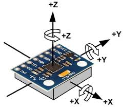
Instead of relying on an Analog-to-Digital Converter (ADC), the XIAO RP2350 reads the sensor values directly through digital communication. The MPU6050 contains internal registers that store high-precision measurements, which the microcontroller accesses via the I²C interface. For instance, the onboard accelerometer measures acceleration in g-forces along the X, Y, and Z axes, while the gyroscope tracks rotational speed in degrees per second. These physical forces are represented as 16-bit digital data, providing a high level of resolution that can then be processed to determine orientation, complex movement patterns, or precise tilt angles.
The implementation of the MPU6050 module is widely recognized in the field for its efficiency in motion tracking, offering a compact way to gather real-time data without the need for additional analog conversion stages. By bypassing the traditional analog-to-digital limitations, the system achieves greater signal integrity and lower power consumption. This makes the combination of the RP2350 and the MPU6050 an ideal platform for developing reactive devices that require stable and reliable motion feedback in a small form factor.
Iteration & Advanced Motion Analysis
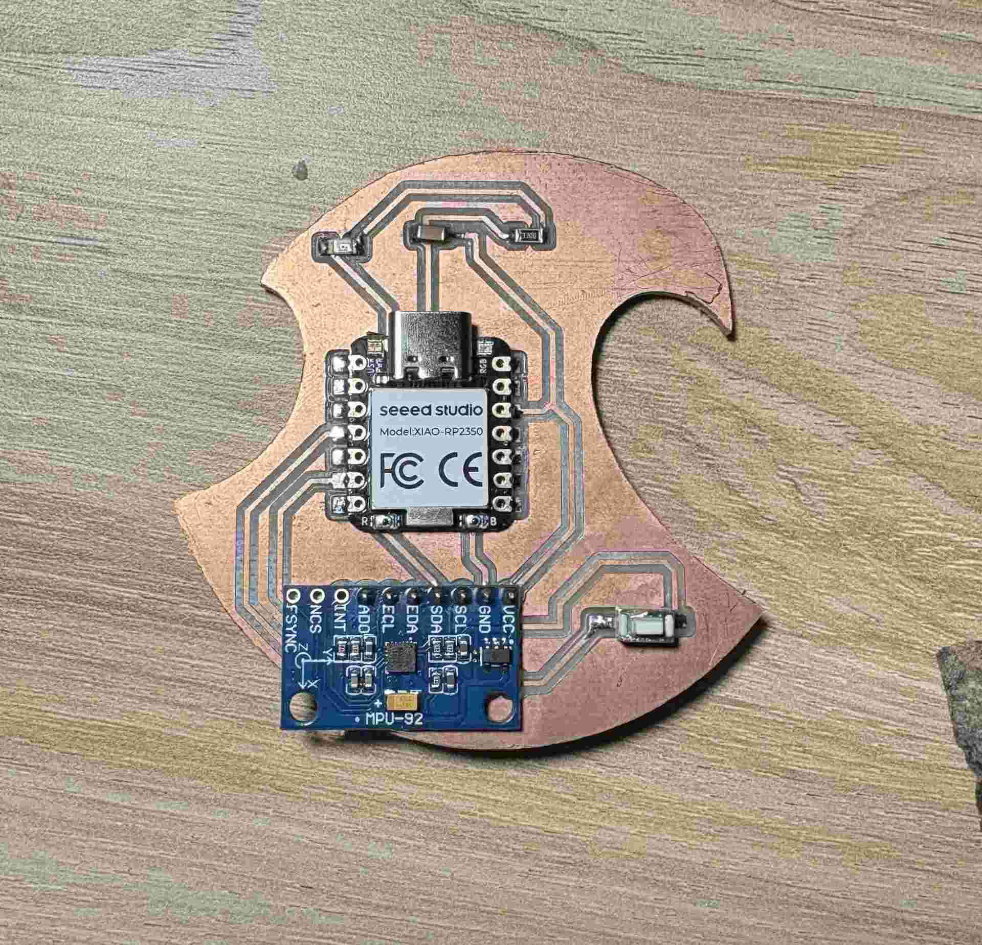
For this assignment, I chose to build upon a previous iteration of my custom PCB which already integrated the MPU6050 module. By leveraging this existing hardware foundation, I was able to shift my focus from basic sensor integration toward more complex data processing. This approach not only demonstrates the scalability of my earlier designs but also allowed for a more efficient development cycle, focusing on high-level motion analysis rather than low-level troubleshooting.
In particular, I expanded the firmware logic to calculate Jerk, which is defined as the rate of change of acceleration over time ($j = \frac{da}{dt}$). While acceleration measures the change in velocity, jerk quantifies the abruptness or "smoothness" of a movement. In a digital system, this is implemented as a discrete derivative: I calculated the difference between the current acceleration reading ($a_n$) and the previous one ($a_{n-1}$), divided by the sampling interval ($\Delta t$).
Using the real-time data from the MPU6050's three axes, this jerk calculation becomes a powerful tool for detecting sudden impacts or erratic motion patterns that simple acceleration thresholds might miss. By reusing the established I²C communication and calibration routines from my previous work, I successfully implemented this dynamic behavior analysis, providing a much more nuanced understanding of how the device interacts with its environment.
Firmware Implementation: Bit-Banging I²C & Jerk Logic
The following code demonstrates the manual implementation of the I²C protocol to interface with the MPU6050 and the discrete calculation of Jerk for motion analysis.
#define SCL_PIN D5
#define SDA_PIN D6
#define LED_ROBIN D1
#define BUTTON_PIN D3
#define MPU_ADDR 0x68

long JERK_THRESHOLD = 5000;
const int HOLD_TIME = 200;

bool logicInverted = false;
bool lastButtonState = HIGH;
unsigned long lastPeakMs = 0;

int16_t prev_ax = 0, prev_ay = 0, prev_az = 0;

void i2c_start() {
  pinMode(SDA_PIN, OUTPUT);
  digitalWrite(SDA_PIN, HIGH); digitalWrite(SCL_PIN, HIGH);
  delayMicroseconds(5);
  digitalWrite(SDA_PIN, LOW); delayMicroseconds(5);
  digitalWrite(SCL_PIN, LOW);
}

void i2c_stop() {
  pinMode(SDA_PIN, OUTPUT);
  digitalWrite(SDA_PIN, LOW); digitalWrite(SCL_PIN, HIGH);
  delayMicroseconds(5);
  digitalWrite(SDA_PIN, HIGH); delayMicroseconds(5);
}

bool i2c_write(uint8_t byte) {
  pinMode(SDA_PIN, OUTPUT);
  for (int i = 0; i < 8; i++) {
    digitalWrite(SDA_PIN, (byte & 0x80) ? HIGH : LOW);
    byte <<= 1; delayMicroseconds(5);
    digitalWrite(SCL_PIN, HIGH); delayMicroseconds(5);
    digitalWrite(SCL_PIN, LOW);
  }
  pinMode(SDA_PIN, INPUT_PULLUP);
  digitalWrite(SCL_PIN, HIGH); delayMicroseconds(5);
  bool ack = (digitalRead(SDA_PIN) == LOW);
  digitalWrite(SCL_PIN, LOW);
  return ack;
}

uint8_t i2c_read(bool ack) {
  uint8_t byte = 0;
  pinMode(SDA_PIN, INPUT_PULLUP);
  for (int i = 0; i < 8; i++) {
    digitalWrite(SCL_PIN, HIGH); delayMicroseconds(5);
    byte = (byte << 1) | digitalRead(SDA_PIN);
    digitalWrite(SCL_PIN, LOW); delayMicroseconds(5);
  }
  pinMode(SDA_PIN, OUTPUT);
  digitalWrite(SDA_PIN, ack ? LOW : HIGH);
  digitalWrite(SCL_PIN, HIGH); delayMicroseconds(5);
  digitalWrite(SCL_PIN, LOW);
  return byte;
}

void setup() {
  Serial.begin(115200);
  pinMode(LED_ROBIN, OUTPUT);
  digitalWrite(LED_ROBIN, LOW);
  pinMode(BUTTON_PIN, INPUT_PULLUP);
  pinMode(SCL_PIN, OUTPUT);
  pinMode(SDA_PIN, INPUT_PULLUP);

  delay(3000);
  Serial.println("--- LED ROBIN: Jerk Monitoring System ---");

  i2c_start();
  i2c_write(MPU_ADDR << 1);
  i2c_write(0x6B);
  i2c_write(0);
  i2c_stop();
}

void loop() {
  bool currentBtn = digitalRead(BUTTON_PIN);
  if (lastButtonState == HIGH && currentBtn == LOW) {
    logicInverted = !logicInverted;
    delay(200);
  }
  lastButtonState = currentBtn;

  i2c_start();
  i2c_write(MPU_ADDR << 1);
  i2c_write(0x3B);
  i2c_stop();

  i2c_start();
  i2c_write((MPU_ADDR << 1) | 1);
  int16_t ax = (i2c_read(true) << 8) | i2c_read(true);
  int16_t ay = (i2c_read(true) << 8) | i2c_read(true);
  int16_t az = (i2c_read(true) << 8) | i2c_read(false);
  i2c_stop();

  long jerkX = abs(ax - prev_ax);
  long jerkY = abs(ay - prev_ay);
  long jerkZ = abs(az - prev_az);
  long totalJerk = jerkX + jerkY + jerkZ;

  prev_ax = ax;
  prev_ay = ay;
  prev_az = az;

  if (totalJerk > JERK_THRESHOLD) {
    lastPeakMs = millis();
  }

  bool alert = (millis() - lastPeakMs < HOLD_TIME);

  if (!logicInverted) digitalWrite(LED_ROBIN, alert ? HIGH : LOW);
  else digitalWrite(LED_ROBIN, alert ? LOW : HIGH);

  long accelMagnitude = abs(ax) + abs(ay) + abs(az);

  Serial.print("Accel_Magnitude:"); Serial.print(accelMagnitude);
  Serial.print(",");
  Serial.print("Total_Jerk:"); Serial.println(totalJerk);

  delay(20);
}
Data Visualization: Acceleration vs. Jerk
In this demonstration, the focus shifts to the real-time data stream processed by the XIAO RP2350. By utilizing the Serial Plotter, we can simultaneously visualize two distinct metrics derived from the MPU6050 sensor:
- Acceleration Magnitude: Represented as the sum of the absolute values of the X, Y, and Z axes, showing the overall intensity of the motion.
- Total Jerk: Calculated as the discrete derivative of the acceleration, this graph specifically highlights the spikes caused by sudden changes in movement or impacts.
This side-by-side comparison allows for a precise analysis of how "smooth" or "abrupt" a movement is, providing much more technical insight than a simple binary trigger.
During this week, I developed a deeper understanding of digital input devices by integrating the MPU6050 sensor with the XIAO RP2350 to capture and process motion data. Instead of only reading raw acceleration values, I extended the system to analyze more complex behavior by calculating jerk, allowing me to detect sudden changes and better interpret movement dynamics.
By building on a previous PCB design, I optimized my workflow and focused on higher-level data processing, including implementing manual I²C communication and real-time visualization. Overall, this assignment strengthened my ability to move from simple data acquisition to meaningful analysis, which is essential for creating responsive and intelligent embedded systems.