Computer controlled machining - Assignment:
For this week's assignment, I decided to make a piece of furniture for my cat so he can play on it. This project involved large-scale CNC machining, focusing on interlocking joints and structural stability.
The material provided at the FabLab was a 12mm x 1.22m x 2.44m plywood board, and I used a 1/4" flat end mill for the cutting process. It is essential to follow the safety protocols and prepare the machine correctly:
- Safety Equipment: Before operating the router, I put on the mandatory PPE: steel-toe boots, a lab coat, and safety glasses to protect against debris.
- Machine Selection: At FabLab Puebla, we have the Asiarobot and the March 2/3. I selected the machine based on availability and bed size.
- Design Preparation: I prepared the vector files ensuring that all joints had the necessary "dog-bone" fillets to account for the tool radius.
- Material Setup: I secured the 12mm plywood board to the CNC bed using screws, making sure it was perfectly flat to avoid cutting depth errors.
- Tooling and Zeroing: I installed the 1/4" flat cutter and performed the X, Y, and Z zeroing process to define the starting point of the job.
- Machining: I executed the G-code, starting with the internal pockets and finishing with the external profile cuts to prevent the piece from moving.
- Assembly: Finally, I sanded the edges and assembled the interlocking parts to verify the fit and the structural integrity of the cat furniture.
SolidWorks Design
Driven by a need to expand the functional workspace within my home environment, I undertook the design and fabrication of a custom-built table. This project served as both a practical solution for interior furnishing and an exploration of personalized aesthetic integration. A key feature of the design is the inclusion of a Nightwing emblem detailed along the edges. This symbolic element was incorporated into the mechanical design phase to ensure a seamless fit with the table's geometry, utilizing precise machining or engraving techniques to achieve a clean, professional finish that balances utility with a unique visual identity.
Parametric Aspects of the Design
To make the design fully adaptable, I used SolidWorks Equations to drive the core dimensions. The table consists of several physical pieces, but they are based on three unique designs: the side walls, the horizontal planks, and the bottom plank support. All of these parts were designed parametrically.
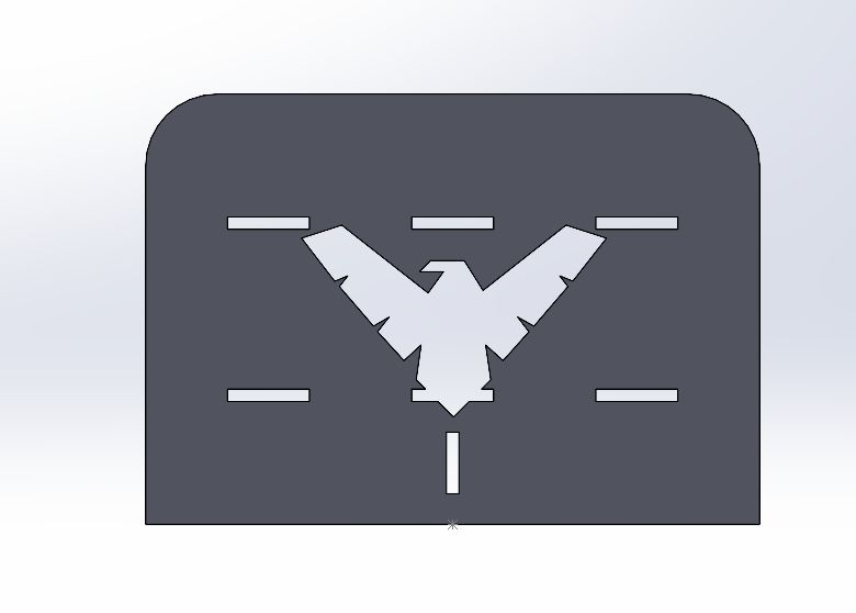
1. Side Walls
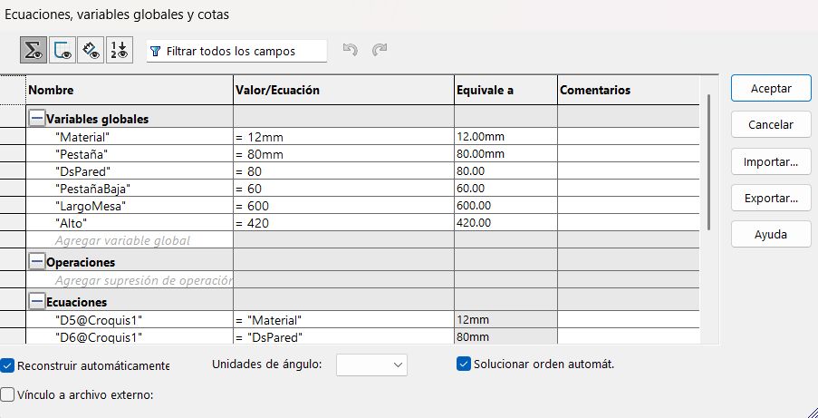
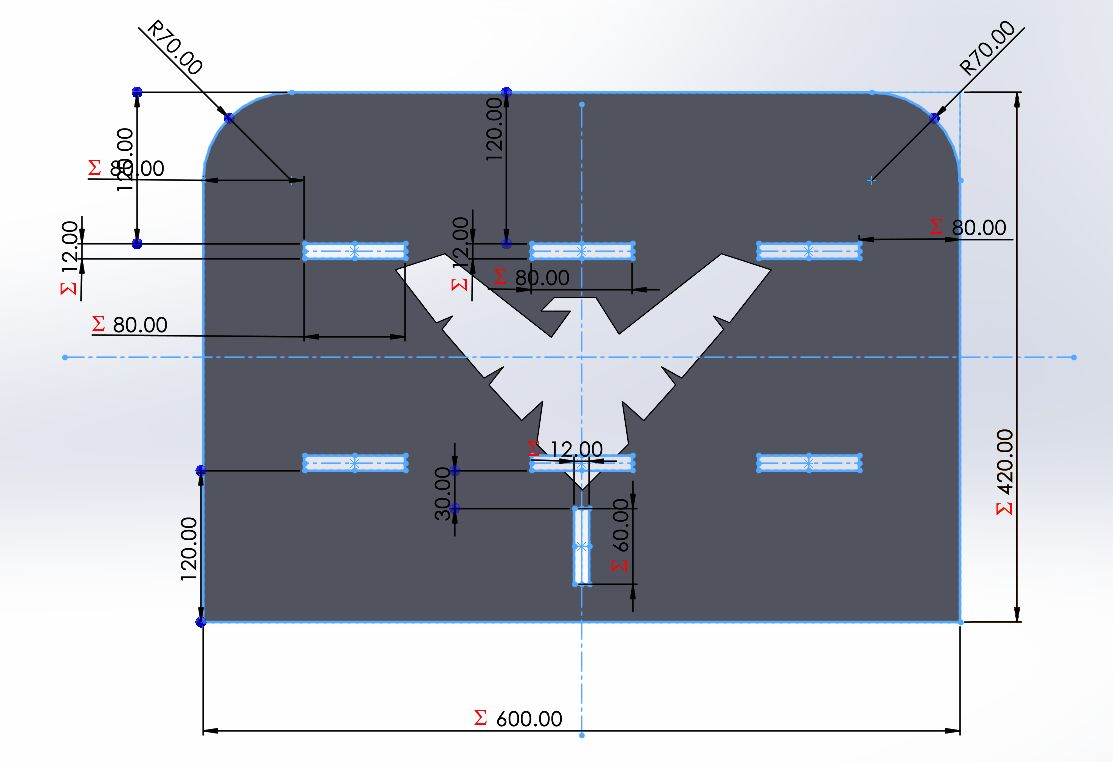
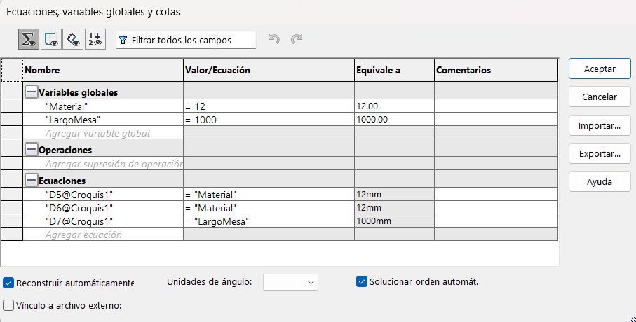
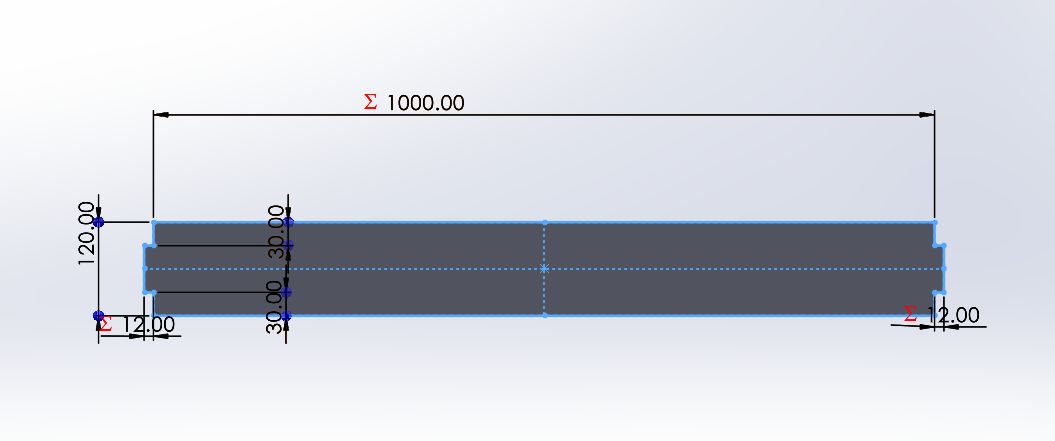
The structure and scale of the side walls are controlled by global variables. Below is the equation manager alongside the 3D model showing the driven dimensions.
Equations: Side Wall Parameters
Model: Exposed Dimensions
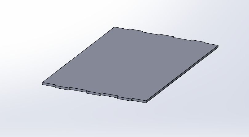
2. Horizontal Planks
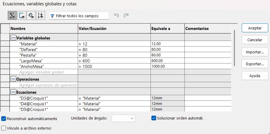
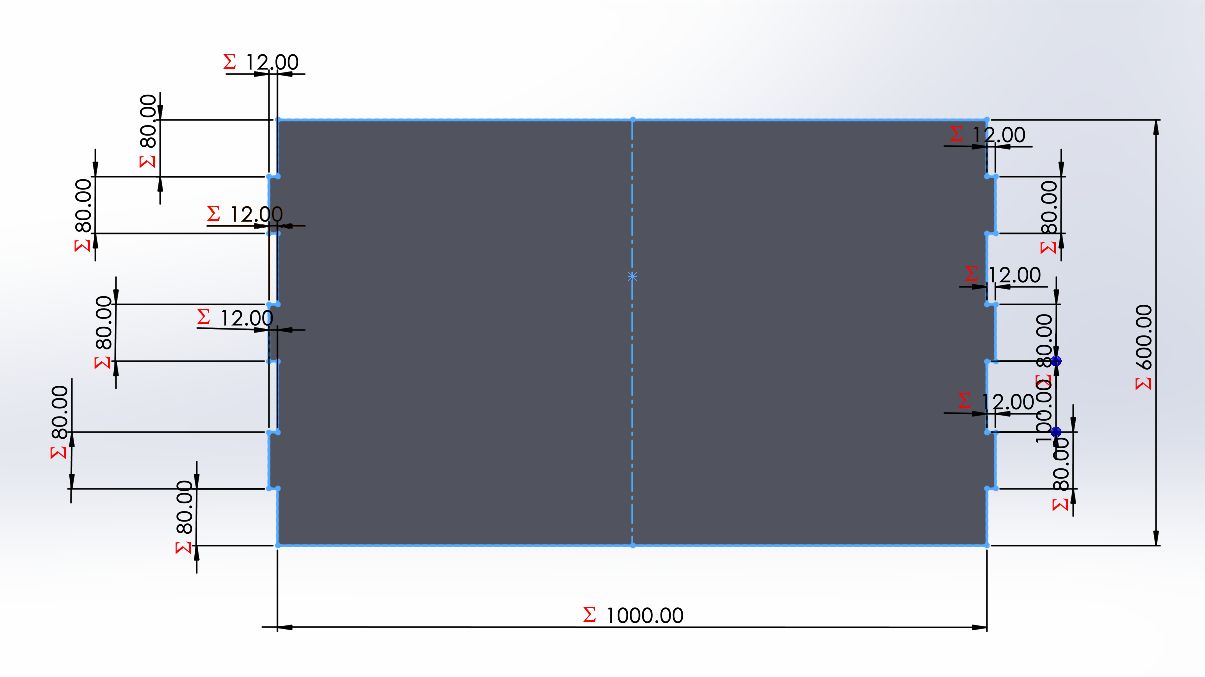
Similarly, the horizontal planks rely on their own set of equations to ensure they assemble perfectly with the side walls.
Equations: Plank Parameters
Model: Exposed Dimensions
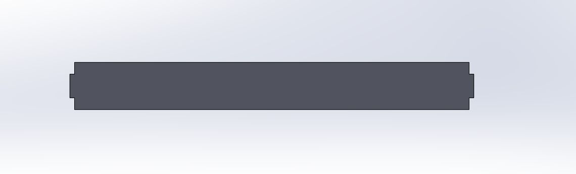
3. Bottom Plank Support
The structural support for the bottom plank also utilizes global variables to maintain alignment and structural integrity when the table dimensions change.
Equations: Support Parameters
Model: Exposed Dimensions
Vcarve
To prepare our designs for the CNC router, we utilize VCarve Pro as our primary CAD/CAM solution. This software is instrumental in translating our vector-based geometry into precise, machine-specific instructions. The workflow focuses on defining the physical properties of the workpiece—such as material thickness and XY datum position—while assigning specialized toolpaths for both the structural elements and the decorative engravings. By utilizing VCarve's advanced simulation features, we can verify the machining strategy and estimate runtimes before committing to the physical material, ensuring high-quality output and minimizing waste. The process is executed through the following standardized steps:
1. Exporting Vectors: I converted the 3D solid model into a 2D technical drawing and exported it as a .DXF file to ensure compatibility with the CAM software.
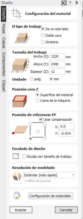
2. Job Setup & Material Configuration: In this step, I defined the physical constraints for the CNC machining process based on the stock material. Following the parameters shown in the "Configuración del material" menu:
- Job Type: Single-sided (De un solo lado).
- Job Size: Width (X) 1220mm, Height (Y) 2440mm, and a Thickness (Z) of 12mm.
- Z-Zero Position: Set to the Material Surface (Superficie del material) to ensure accurate depth calculation relative to the top of the plank.
- XY Datum Position: Set to the Bottom-Left corner (X: 0.0, Y: -0.934 with offset) to align the digital origin with the physical home of the CNC.
- Modeling Resolution: Standard (Estándar) for optimized processing speed.
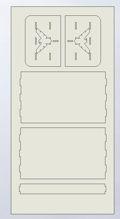
3. Importing Vectors: Import the .DXF file into the workspace. I centered the vectors on the material to optimize the cutting area.
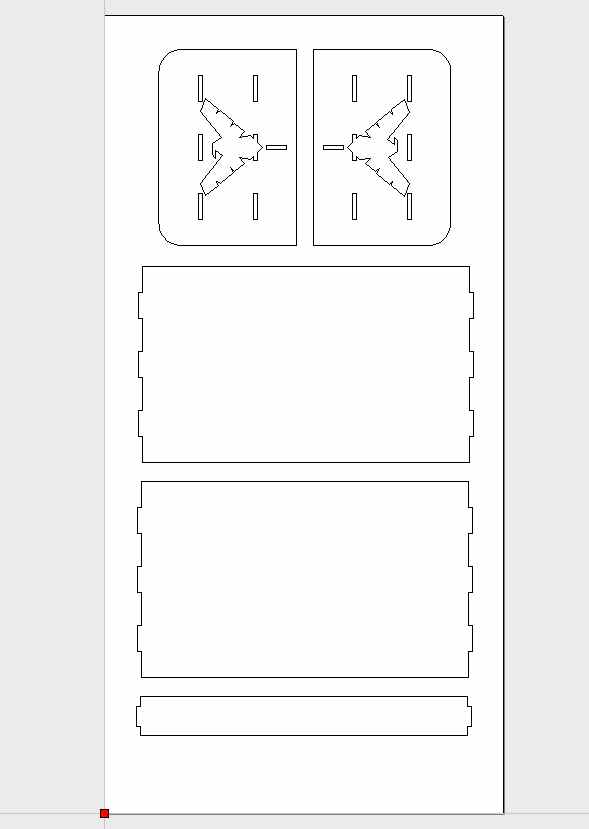
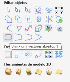
4. Vector Healing: Use the 'Join Open Vectors' tool. This ensures all shapes are closed loops, which is mandatory for applying profile toolpaths.
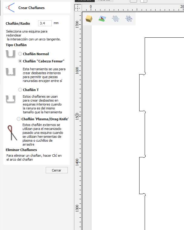
5. Corner Filleting: I applied Dog-bone fillets to all internal 90-degree corners. This accounts for the tool's radius, allowing the interlocking plywood parts to fit perfectly.
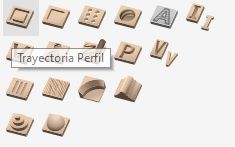
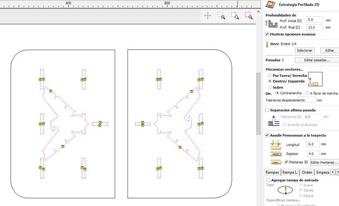
6. Internal Toolpaths: Select the inner vectors first. I applied a Profile Toolpath to the inside of the lines to create the slots and pockets of the furniture.
7. Cutting Parameters: I set the cut depth to 12.5mm (slightly over the thickness) and selected a 1/4" Flat End Mill. I also added Tabs to keep the pieces secured during the final passes.
8. External Toolpaths: I repeated the process for the outer boundaries, setting the machining strategy to 'Outside' to maintain the correct final dimensions of the parts.
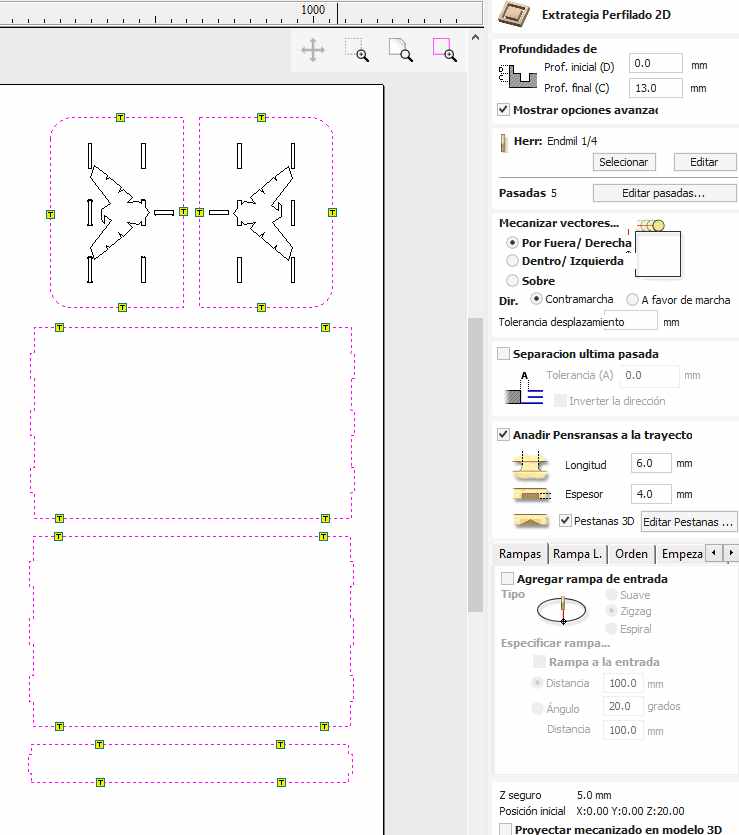
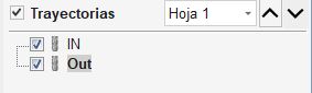
9. Toolpath Ordering: I organized the operation sequence to perform Inside cuts first and Outside cuts last. This prevents the pieces from detaching before the job is finished.
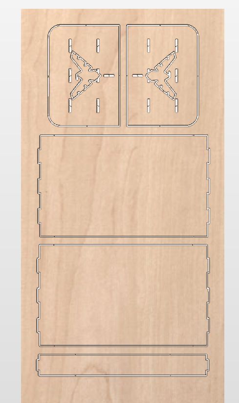
10. 3D Simulation: I ran the 3D preview to verify the toolpaths. This simulation helps identify potential errors, such as missing tabs or incorrect cut depths, before going to the machine.
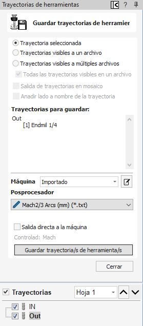
11. Exporting G-code: Finally, I saved the toolpaths using the appropriate post-processor for the CNC router to generate the .tap / .nc files.
Machining
The fabrication phase here at Fab Lab Puebla, houses a variety of industrial-grade equipment, including the Asia Robotics and the March CNC Router systems. For the specific requirements of this assignment, I utilized the March machine to execute the toolpaths generated in our CAM software. The selection of this machine allowed for the precise milling of the table's structural components and the detailed engraving of the Nightwing emblem. By configuring the Mach3 control interface specifically for the March router, I was able to manage real-time spindle speeds and feed rates, ensuring a high-quality finish that adheres to the technical specifications of the design.
Machine Used
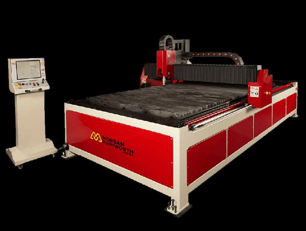
A Morgan Rushworth large-format CNC router.
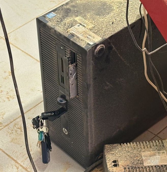
1. Data Transfer: Connect the USB drive containing the processed G-code file to the CNC's control computer to begin the interface setup.
2. Software Initialization: Launch the machine control software (Mach3/March or the proprietary Asiarobot interface) and ensure the emergency stop is disengaged.
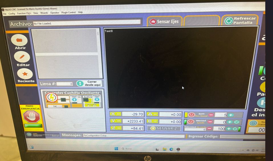
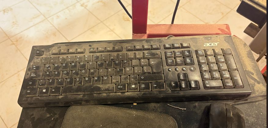
3. Manual Jogging: Use the keyboard arrows for XY movement (holding Shift for rapid jogging). For the Z-axis, use the PgUp and PgDn keys to position the spindle above the material.
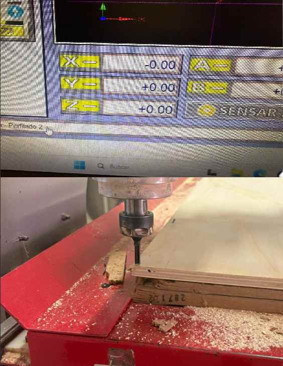
4. Work Origin & Stock Securing: Carefully move the tool to the corner of the plywood plank to set the XY Datum. Once positioned, press the Zero Axis buttons to establish the Work Coordinate System (WCS). Crucial Step: For this specific machine, the board must be securely nailed to the sacrificial bed to prevent any shifting or vibrations during the high-speed milling process.
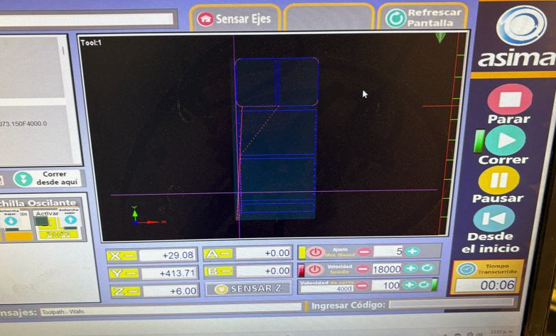
5. Loading the G-code: Select the file from the directory. Verify the toolpath preview in the software to confirm it matches the intended design and material orientation.
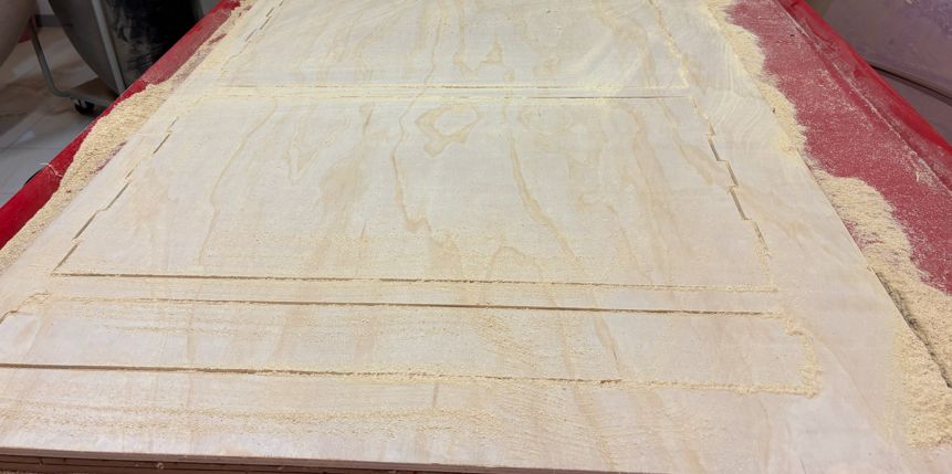
7. Part Extraction: Once the cycle is complete, carefully cut the tabs using a chisel or saw to release the machined parts from the remaining plywood sheet.
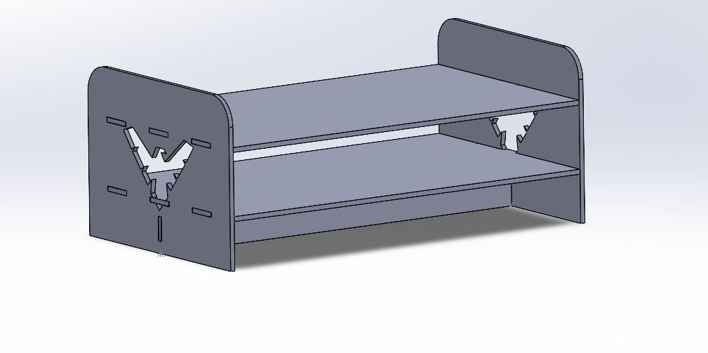
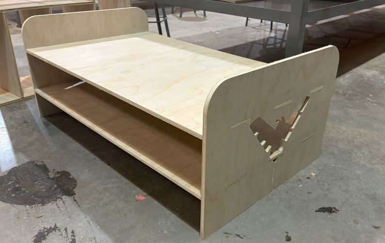
Assembly & Post-Processing: After cutting, I thoroughly cleaned and sanded all edges to remove splinters. The assembly relies on an interlocking structure; I designed the dog-bone joints with a very tight fit to prevent the piece from wobbling or disassembling over time. Due to this precision, a rubber mallet was required to carefully drive the parts together, ensuring a permanent and sturdy friction lock without the need for screws.
Final Result: The finished table is complete. The 12mm plywood provides excellent structural stability, and the parametric design ensured that all press-fit connections remained tight and secure. The Nightwing symbol on the edges adds a clean, personalized touch to the final piece.
This week provided hands-on experience with industrial-grade equipment like the Asia Robotics and March CNC routers. The workflow from vector healing to G-code generation in VCarve Pro highlighted the importance of toolpath ordering and safety protocols. Successfully executing the project on 12mm plywood demonstrated the precision required for large-scale fabrication, particularly when balancing functional structural parts with decorative engravings. Overall, these skills are fundamental for any project involving high-sturdiness furniture and complex assembly systems.
Files
└── Week7Files
    ├── DrawingTable.SLDDRW
    ├── Plank.SLDPRT
    ├── Support.SLDPRT
    ├── Table.SLDASM
    └── Wall.SLDPRT