Computer-Controlled Cutting - Assignment:
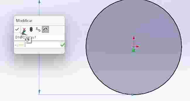
This week consisted of designing and laser cutting 2D parts to understand the laser cutting process, material behavior, kerf, and press-fit tolerances. I decided to use SolidWorks for this, first to explain how do you make the parametric design of a piece, once the piece has been drawn, we need to make a variable, we can either go to tools-equations or directly make it by placing "=" on a dimension and create the variable, once doing this, we can change the variable in equations and redimension the piece anytime we want.
Parametric Design in SolidWorks
Parametric modeling is the foundation of an efficient CAD workflow. Instead of static sketches, it relies on mathematical and logical relationships that allow the model to adapt to changes automatically.
| Concept | How it Works | Importance in Fab Academy |
|---|---|---|
| Geometric Relations | Rules such as "Horizontal", "Coincident", or "Tangent" applied to sketches. | Maintains the design's structural integrity even when dimensions change. |
| Global Variables | A central table where specific values are defined (e.g., material_thickness = 3mm). | Allows the entire assembly to be updated by editing a single numerical value. |
| Equations | Mathematical links between dimensions (e.g., D2 = D1 / 2). | Essential for designs that must scale proportionally, such as gear systems. |
| Design Intent | The logical sequence of features and constraints. | Determines how the model reacts to drastic changes without "breaking" the geometry. |
Parametric Design Workflow
To implement parametric design, we define variables that control the geometry. This can be done via Tools > Equations or by typing "=" directly into a dimension field. Once linked, changing a single variable automatically updates the entire piece.
1. Dimension Linking: Using the "=" prefix to assign a variable to a specific length.
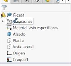
2. Variable Definition: Accessing the equations table to manage global variables.
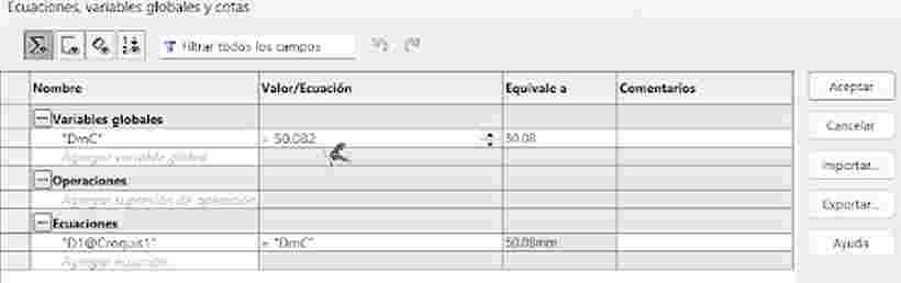
3. Parametric Control: The dimension is now driven by the global equation.
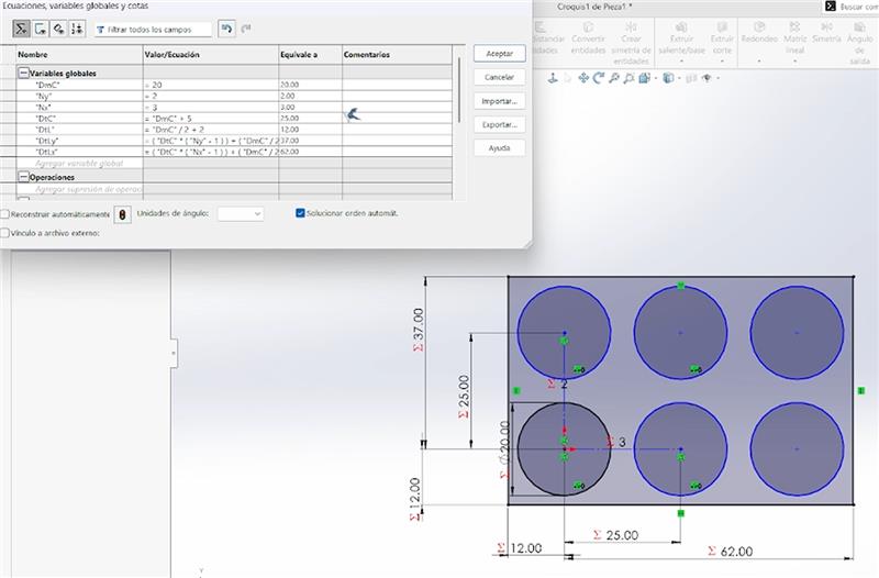
Circular Geometric Patterns
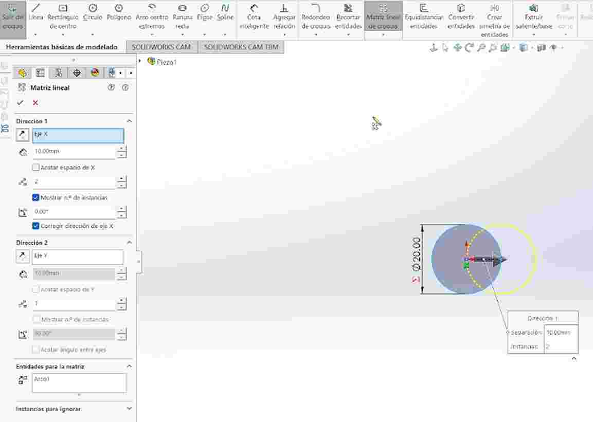
These pieces were generated using an initial circle as a base. I applied linear patterns for the grid layout and circular patterns to create the joint mechanisms within the main geometry.
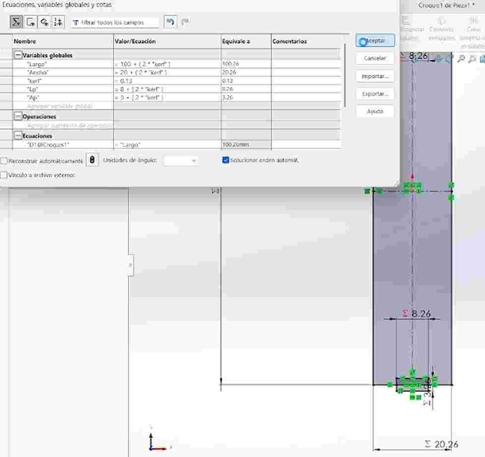
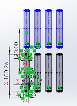
Structural Pillars
The pillars started as a basic rectangular sketch. I utilized rectangular patterns to expand the geometry along the X and Y axes while maintaining parametric consistency.
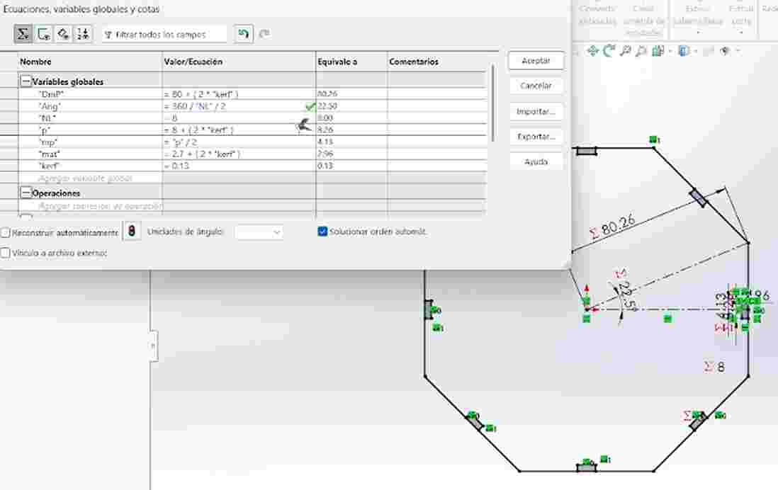
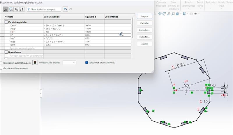
Equation-Driven Polygons
This was a complex task: I used an equation to define the interior angles. This allows me to change the number of sides ($n$) through the parameters and the piece updates its geometry automatically.
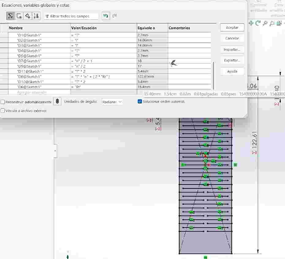
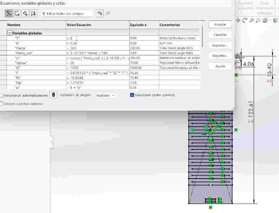
Flexible Living Hinges
Finally, I designed flexible pieces by adjusting the pattern parameters. By modifying these dimensions, I can control the flexibility and structural integrity of the material.
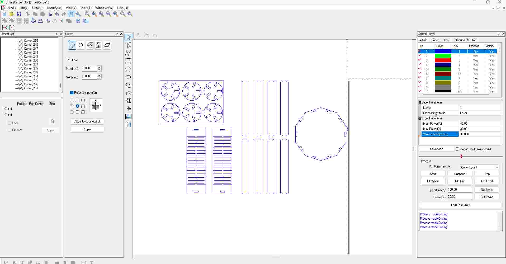
Laser cutting - SmartCarve
SmartCarve Laser Parameters
Successful laser cutting depends on balancing power and speed according to the material's properties. Below are the critical parameters managed in SmartCarve.
| Parameter | Function | Impact on Results |
|---|---|---|
| Speed (mm/s) | The velocity at which the laser head moves across the material. | Slow: Deeper cut but increases charring. Fast: Clean cut but may not penetrate fully. |
| Power (%) | The intensity of the electrical current sent to the laser tube. | Higher power is needed for thicker materials, but excess power can cause fire or melted edges. |
| Corner Power | Power intensity applied when the head decelerates at sharp turns. | Prevents over-burning in corners where the laser lingers longer due to deceleration. |
| Interval (mm) | The distance between lines in raster (engraving) mode. | Defines engraving resolution. Lower values provide higher detail but significantly increase job time. |
| Frequency (Hz) | The number of laser pulses emitted per second. | Crucial for acrylics; high frequency helps achieve a "polished" or flame-like transparent edge. |
For our Laser cutting we need to import our .DXF to SmartCarve and accommodate our pieces in the main page, once doing this we go to file save and save our document as a .oud.
Import the .DXF file into SmartCarve and arrange the pieces on the main workspace according to the material layout.
Once the pieces are properly positioned, go to the File menu and save.
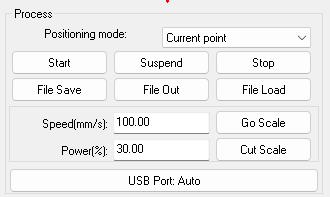
Store the document in the .oud format required for the laser cutting machine.

Then for the Laser Machine we start by following the next steps:
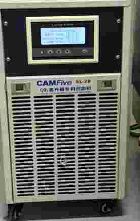
1. Thermal Management: Ensure the water chiller is powered on and running. This is critical to maintain the laser tube at a safe operating temperature and prevent overheating during the job.
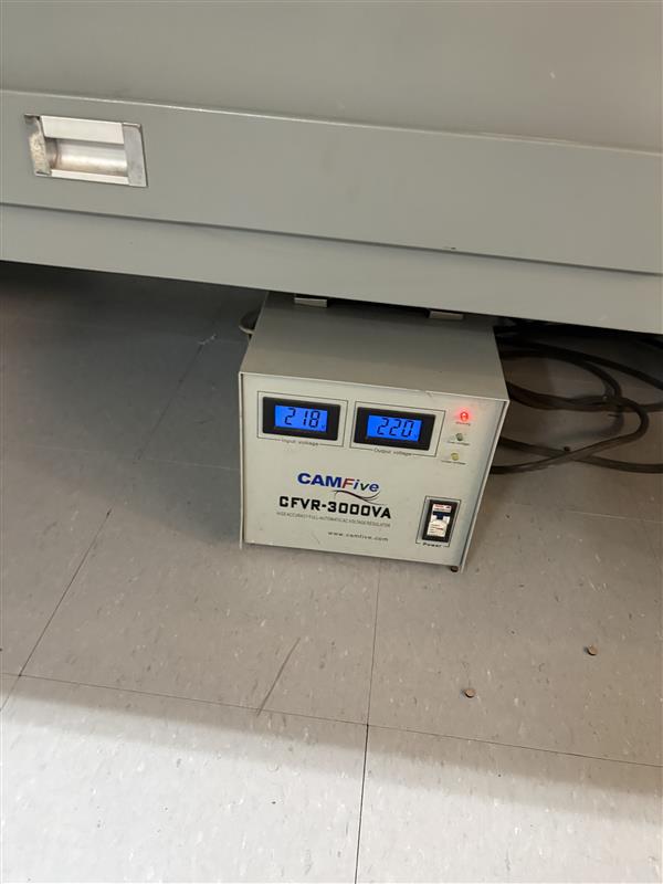
2. Power Stabilization: Turn on the automatic voltage regulator. This protects the laser's sensitive electronic components from power surges and ensures a stable current for consistent cutting quality.
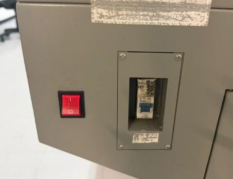
3. Main System Boot: Locate and flip the main power switch on the right side of the machine to boot up the internal controller and the motion system.
4. Safety Protocol: Release the Emergency Stop button by twisting it clockwise. This engages the stepper motors and allows the machine's X and Y axes to move.

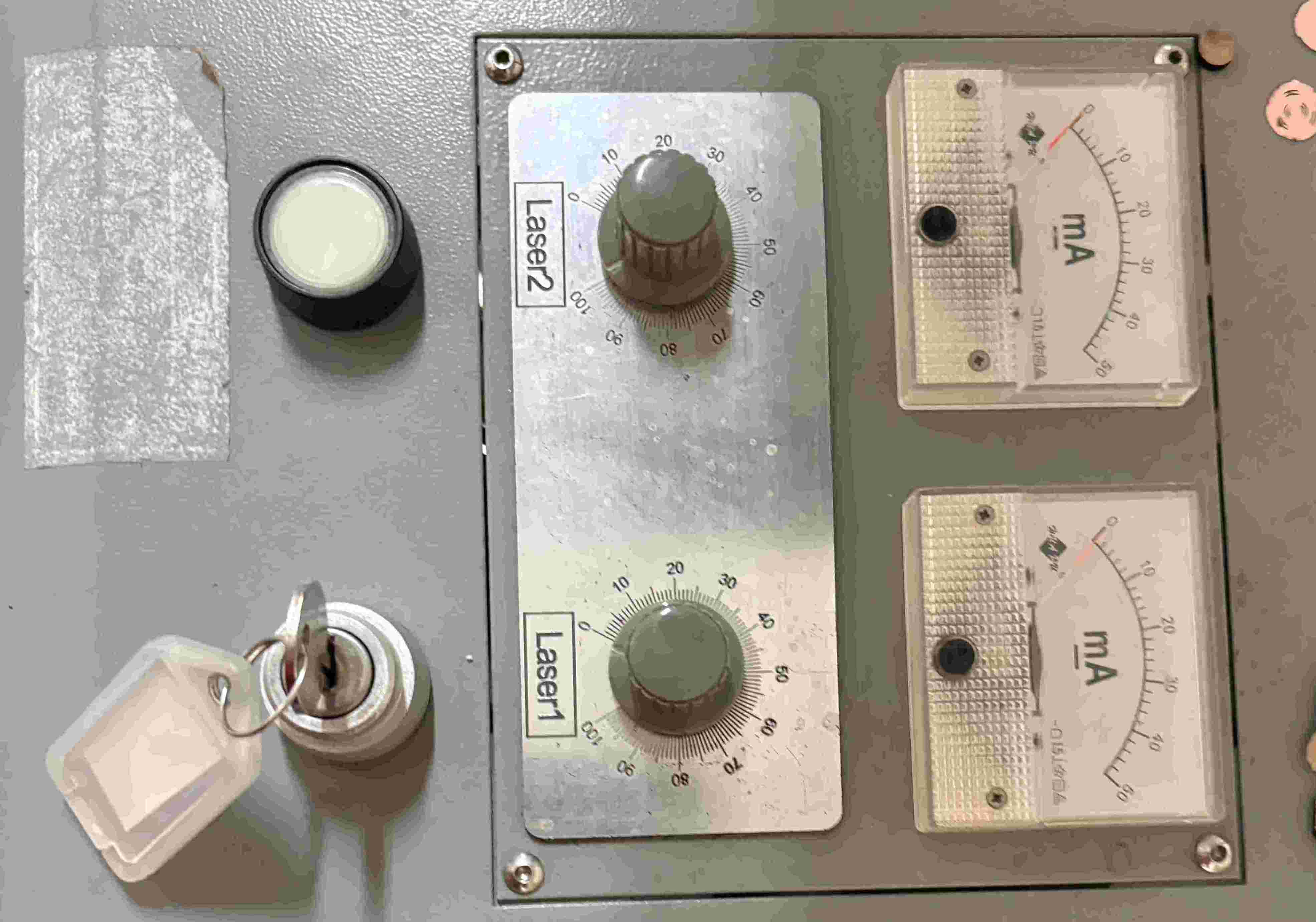
5. Panel Activation: Insert and turn the security key. This activates the Ruida control panel and enables the high-voltage power supply for the laser tube.
6. Defining the Origin: Move the laser head to your starting position using the arrows on the panel, then press the 'Origin' button to set the (0,0) coordinate for your project.
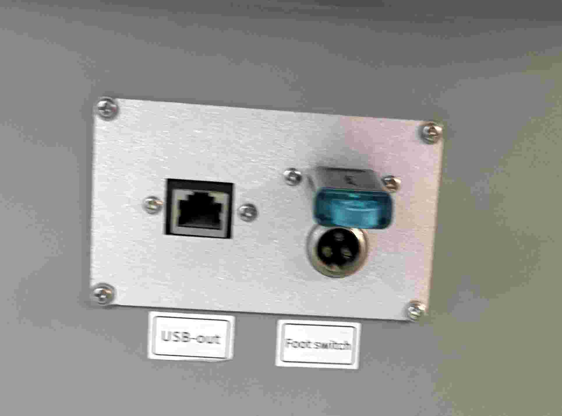
7. Data Transfer: Connect the USB drive containing your compiled .oud files into the dedicated port on the side of the machine.
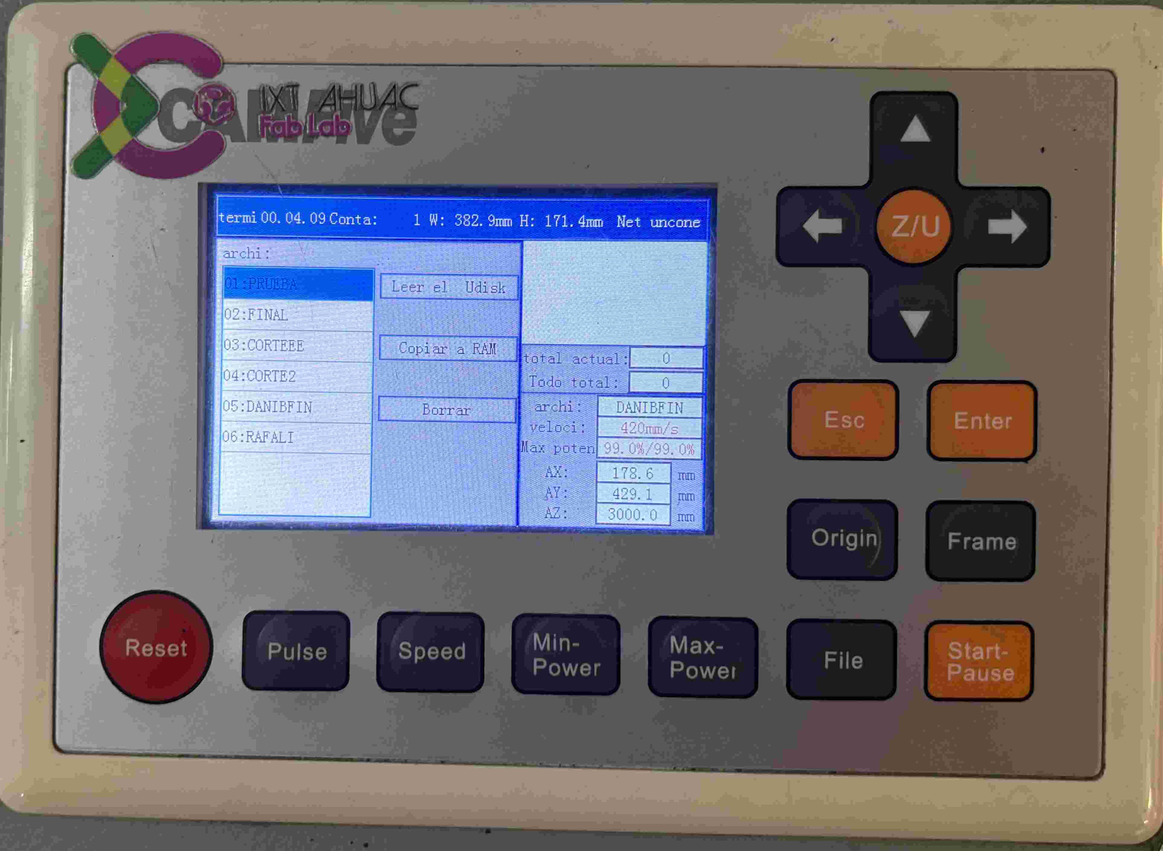
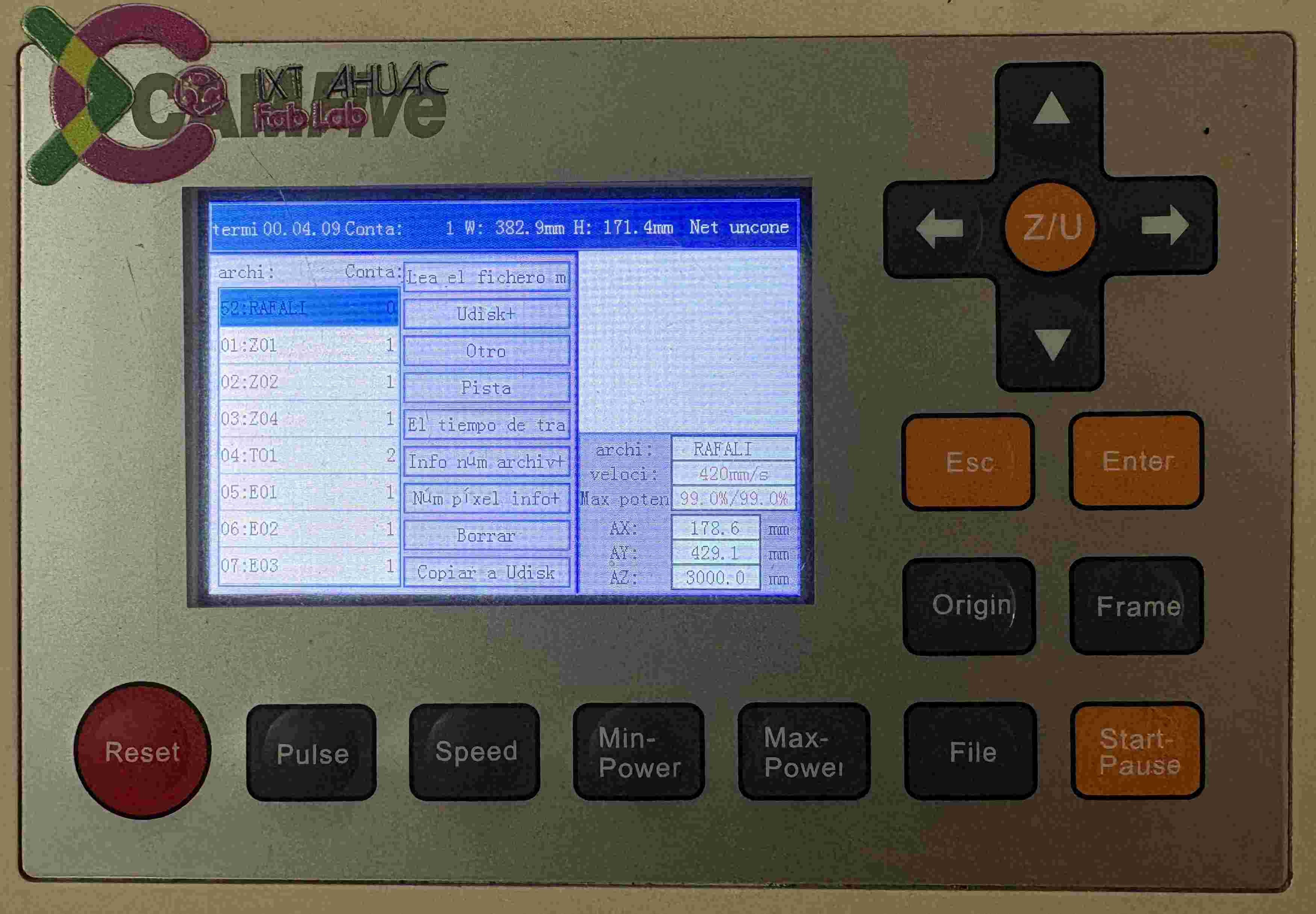
8. File Navigation: Access the menu, navigate to '+Udisk', and read the drive's contents to locate the specific file you exported from the software.
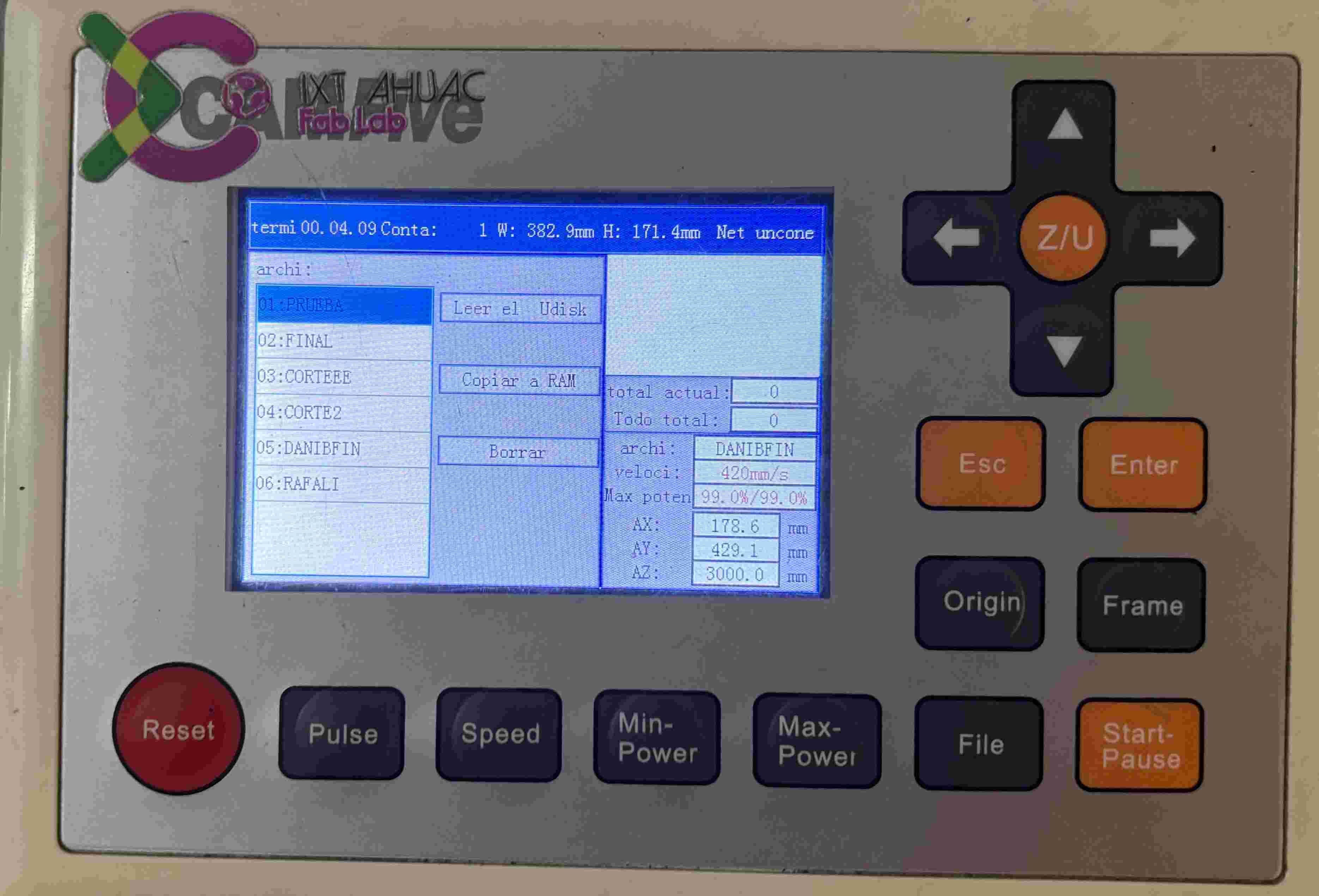
9. Loading to Memory: Select your file and copy it to the machine's internal RAM. This ensures the cut won't be interrupted if the USB is accidentally moved.
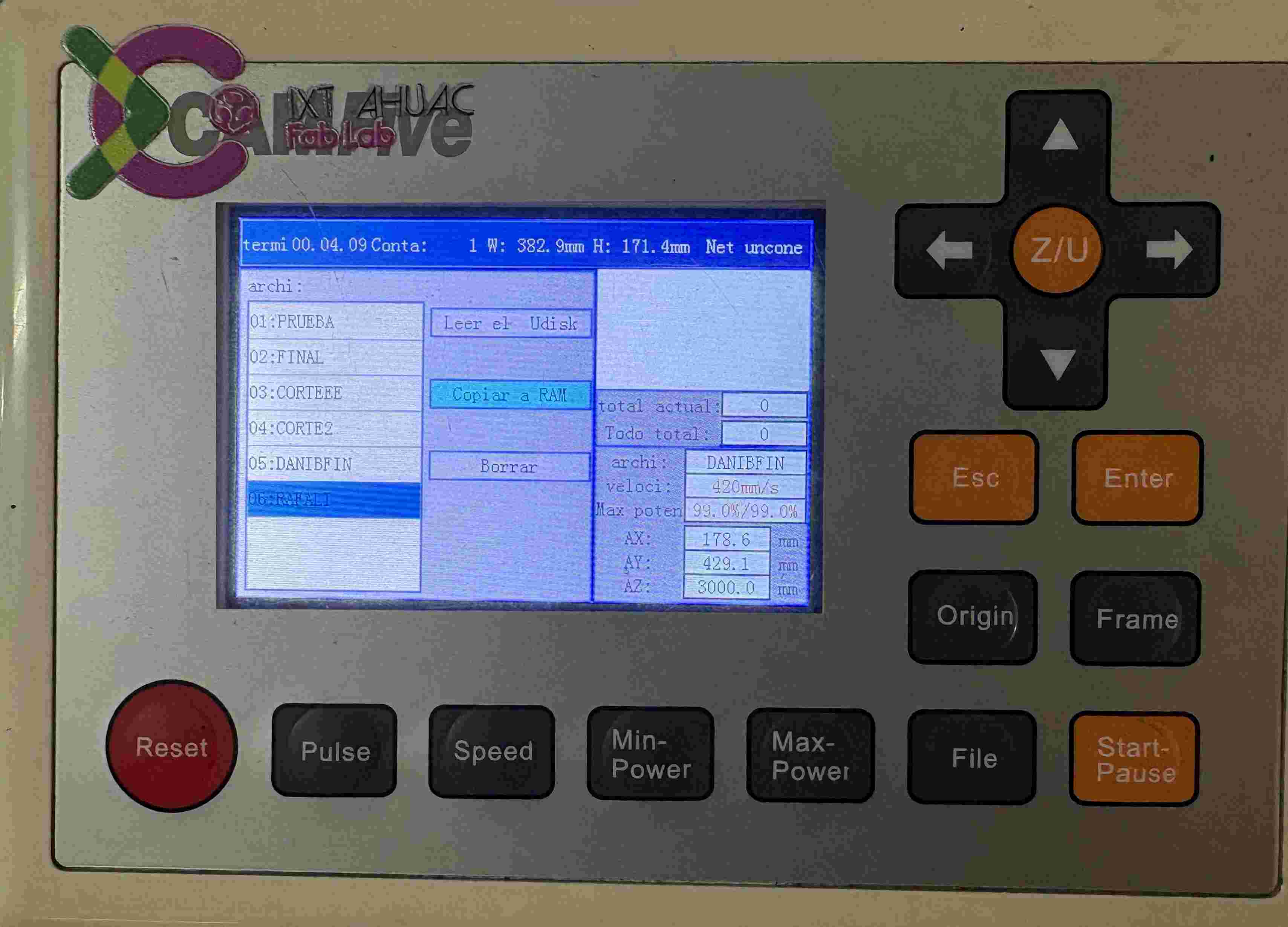
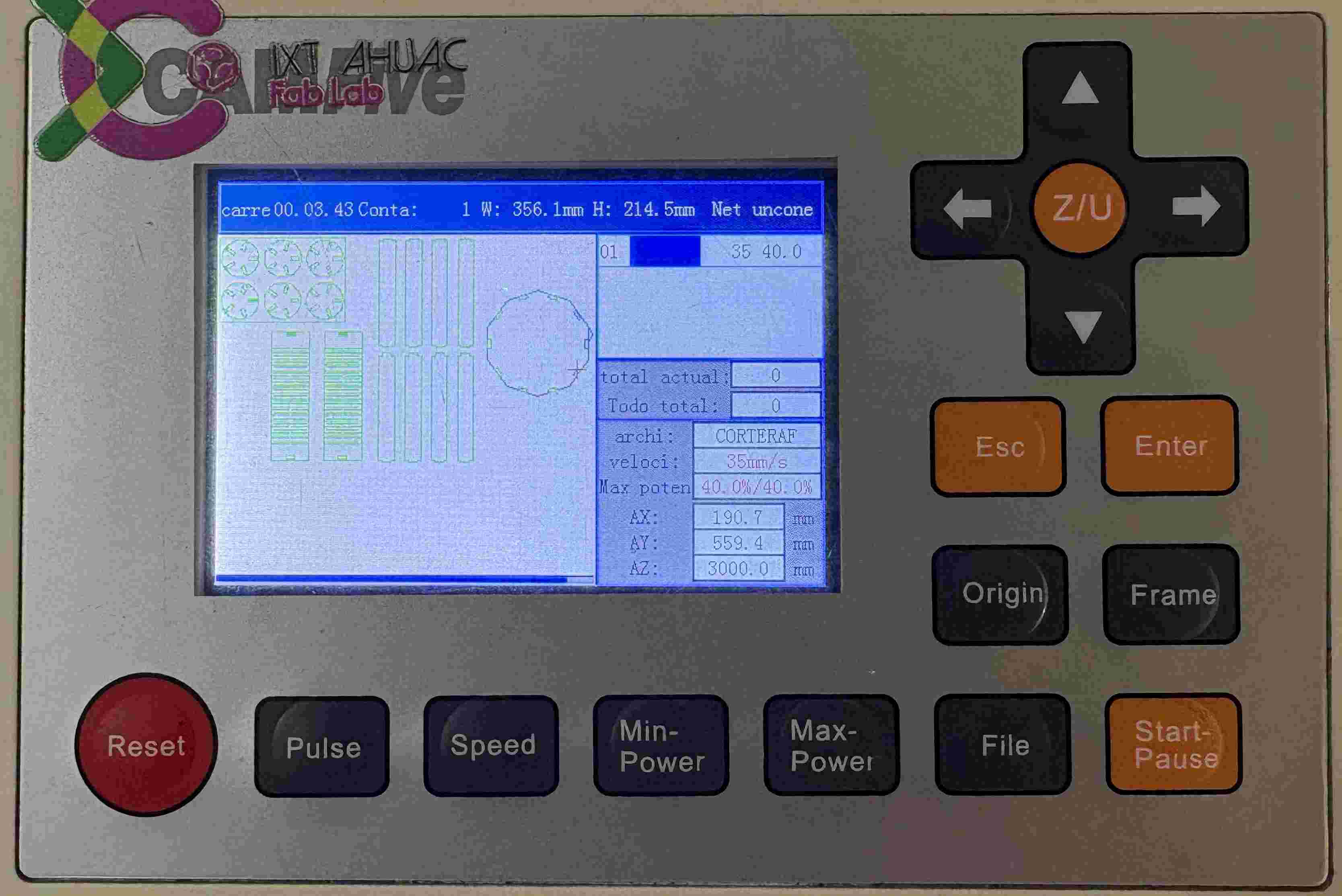
10. Selecting the Job: Press 'Esc' to return to the main menu and select your file from the list of loaded projects in the local memory.
11. Final Execution: Activate the Laser switch on the physical panel and press 'Enter' on the controller to prepare the machine for the start signal.
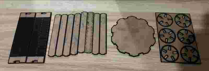
This is how my initial pieces came out, the laser cutter available in our lab has a worn laser tube, which reduces its precision and efficiency. Because of this condition, the machine tends to overburn the material, producing darker edges and slightly larger cuts than expected.
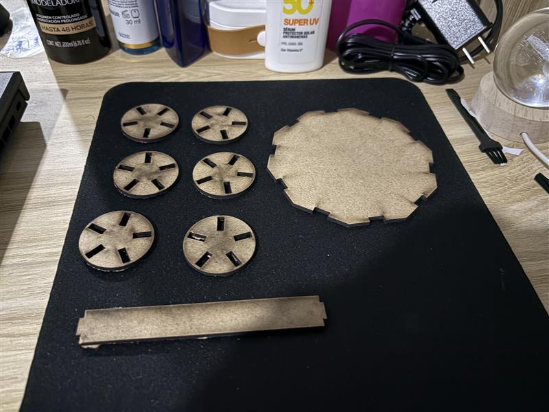
This pieces were incomplete and didn´t come out as I wanted due to some problems I had, so later I did it again and this is how my final pieces came out definitely.

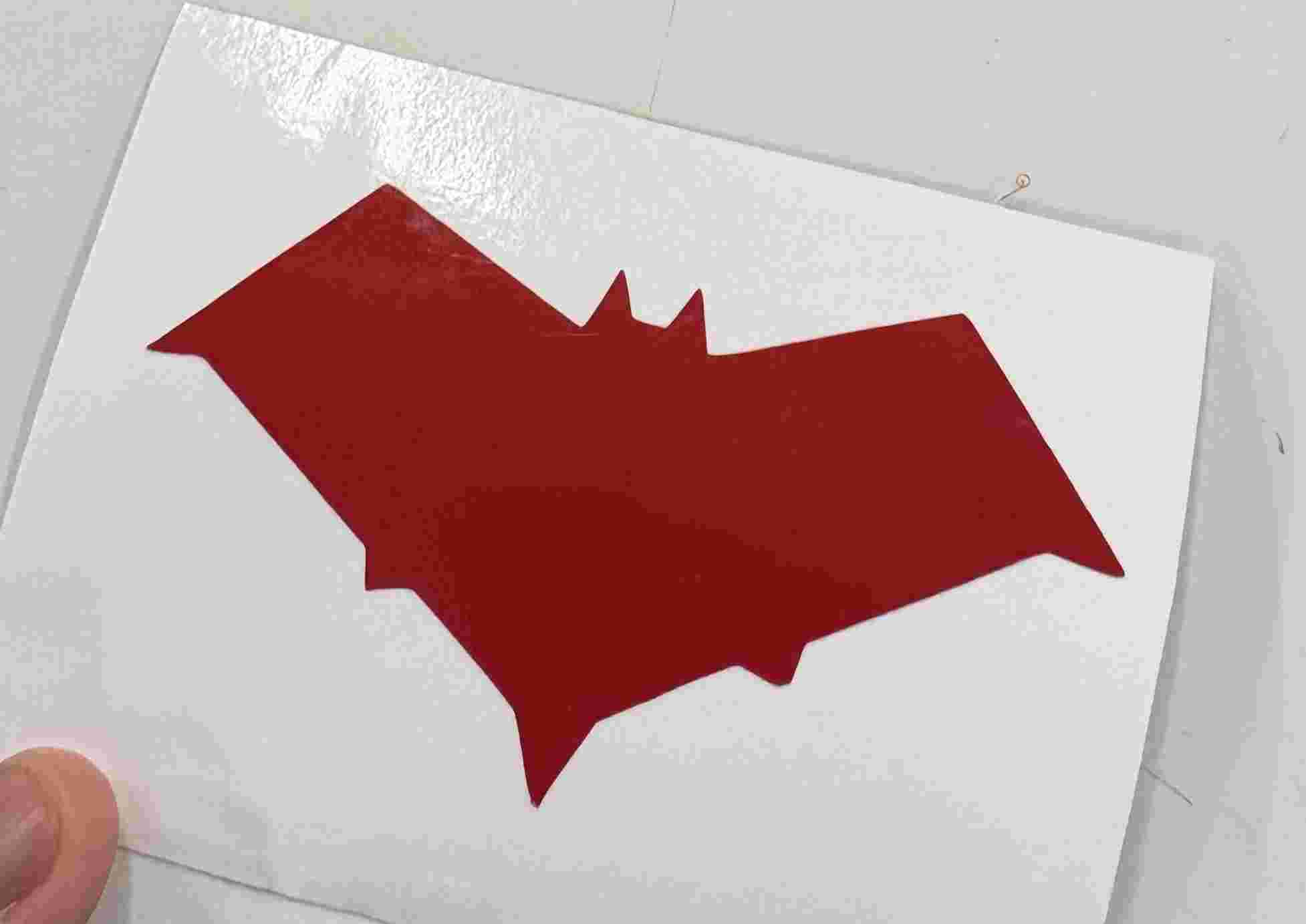
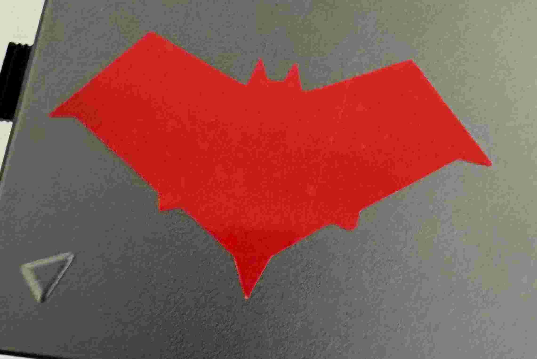
Vinyl Cutting
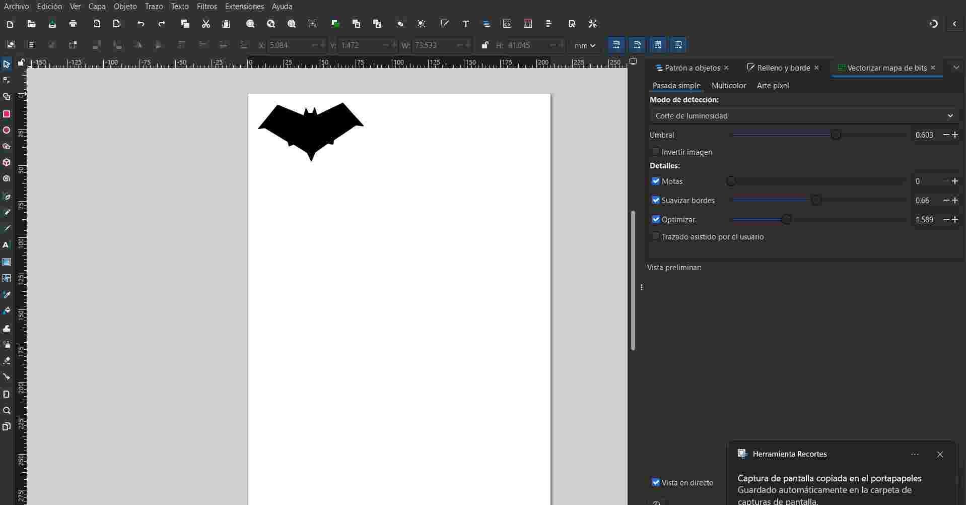
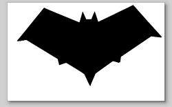
For this section we need to vectorize a bit map of an image, I made it on inkscape and save it as a .svg, after that we need to follow some steps.
1. Vector Preparation: Start with your finalized vectorized image. Ensure all elements are converted to paths and that there are no stray pixels, as the plotter only follows vector paths for cutting.
2. Document Properties: Press Ctrl + Shift + D to open the Document Properties. This step is essential to define the workspace dimensions so they match the physical material loaded in the vinyl cutter.
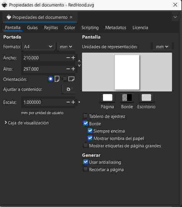
3. Scaling and Resizing: Resize the document page based on your vector's dimensions. Using the "Resize page to drawing or selection" option ensures the plotter recognizes the correct boundaries of your design.
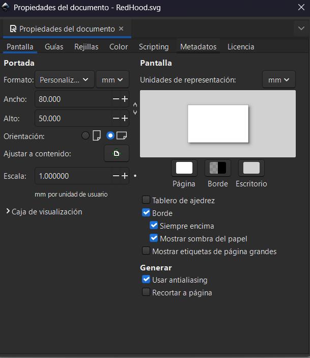
4. Workspace Positioning: Align your vector close to the upper-right corner of the document. This corresponds to the typical 'Home' or 'Origin' position for many vinyl cutters, minimizing material waste.
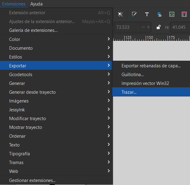
5. Plotter Extension: Navigate to Extensions > Export > Plot. This specific Inkscape extension translates your vector paths into the HPGL language that the cutting machine understands.
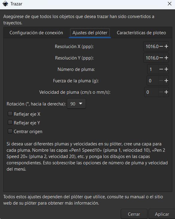
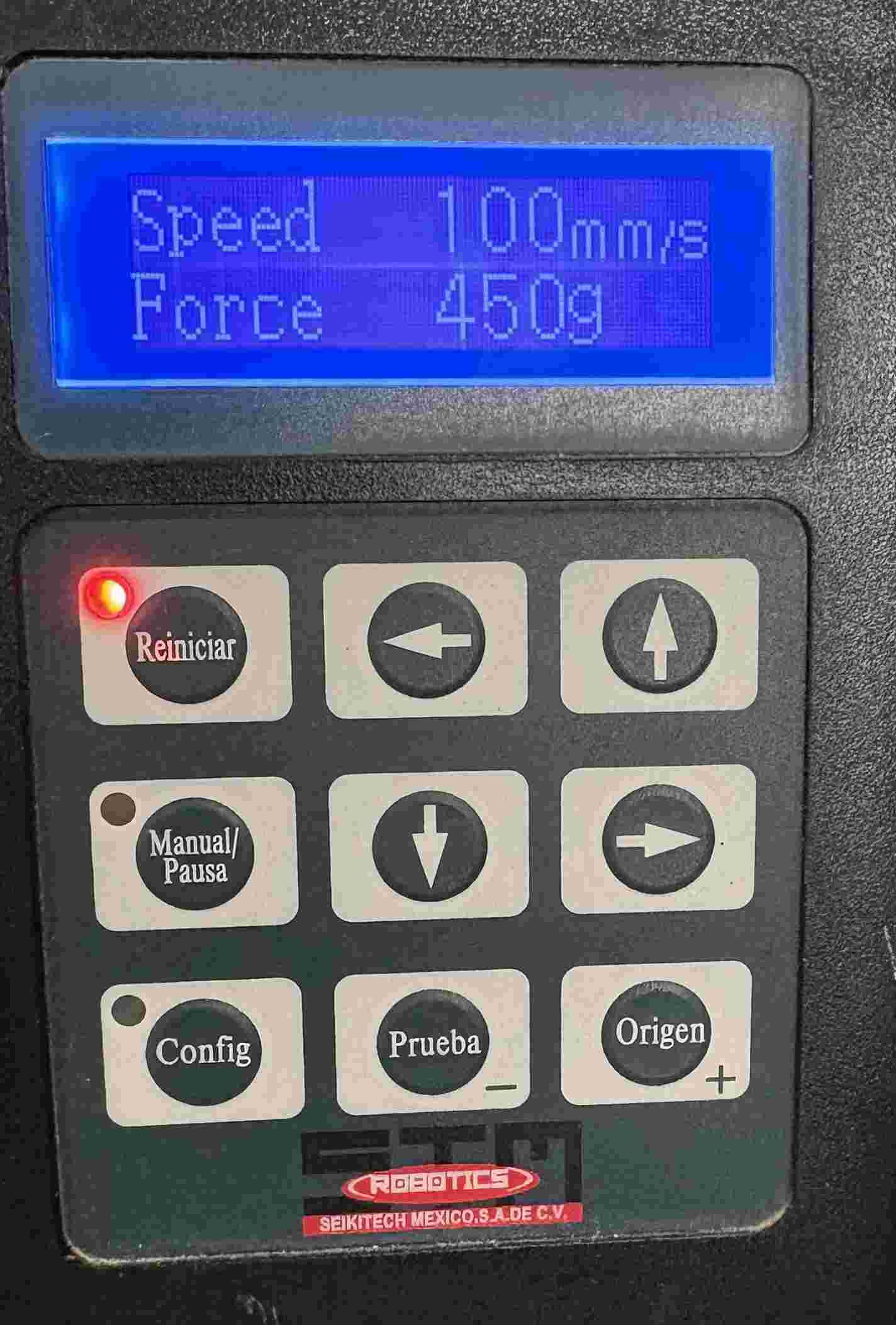
6. Parameter Setup & Execution: Configure the connection settings and cutting speed. Once the blade depth and material force are manually set on the machine, click 'Apply' to send the data and begin the cut.
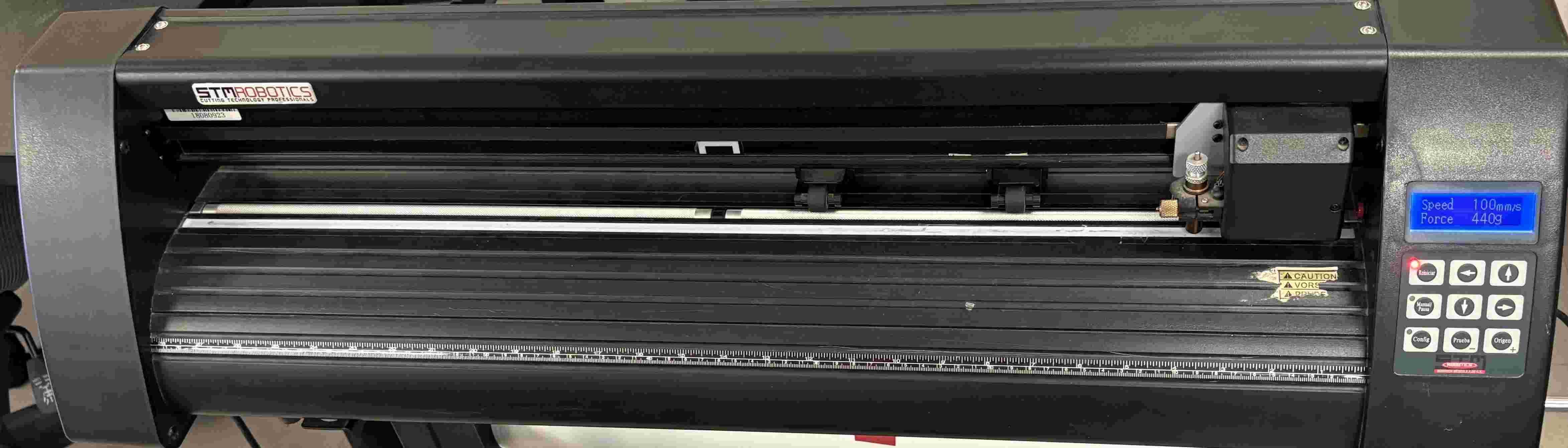
For the cutting of our Vinyl we follow the next steps:
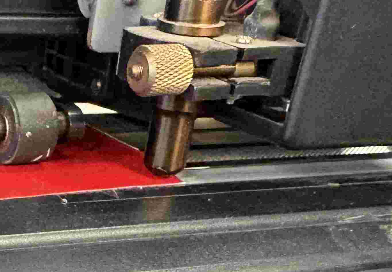
1. Machine Preparation: Ensure the vinyl cutter is powered on and the blade is correctly calibrated for the material thickness. A test cut is recommended to verify pressure settings.
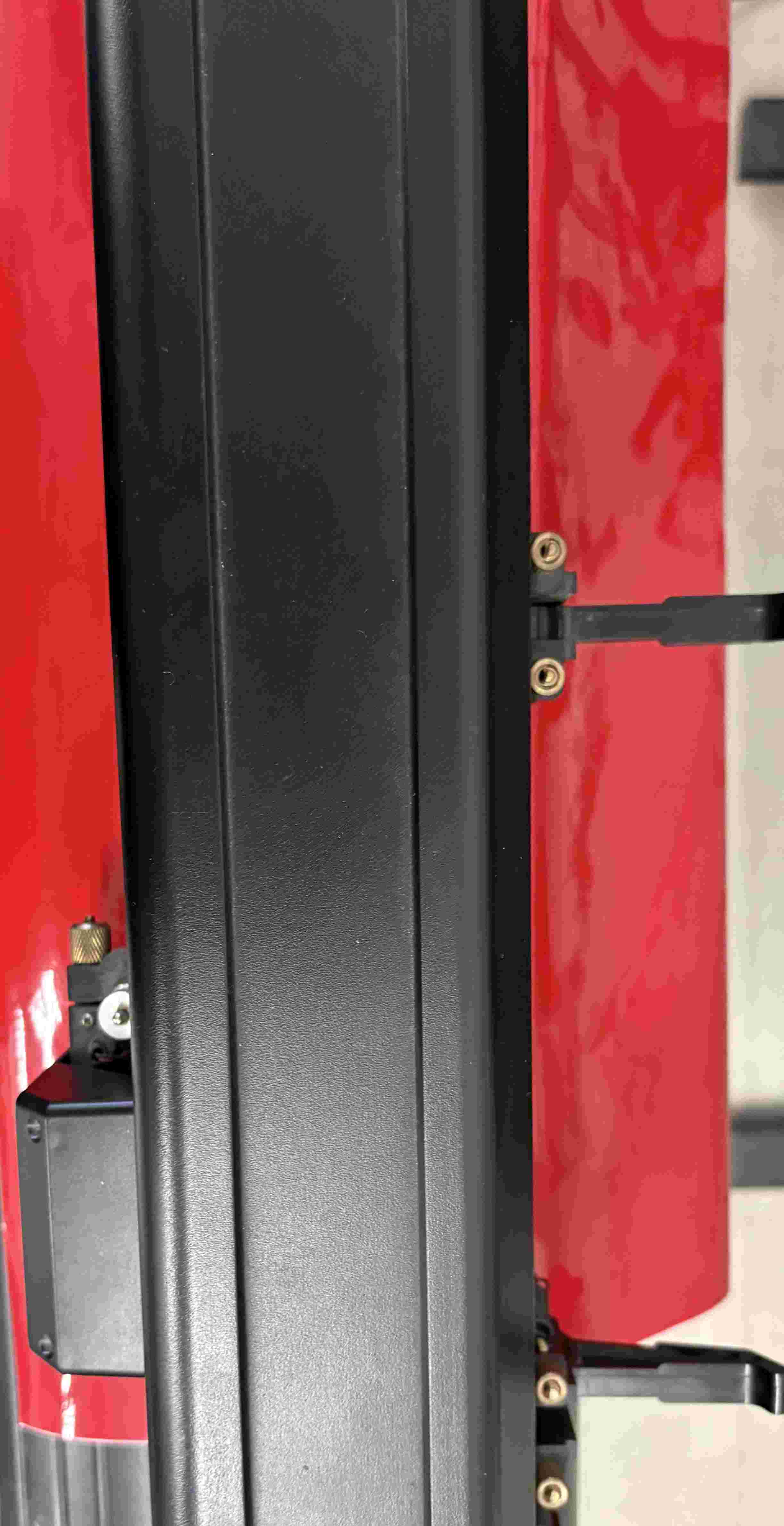
2. Loading Material: Insert the vinyl sheet from the back of the machine. Align it with the guide rollers and lock the pinch rollers to keep the material tensioned during the cutting process.
3. Manual Control: Switch the machine to 'Manual' mode. This allows you to use the arrow keys on the control panel to move the carriage and the material independently.
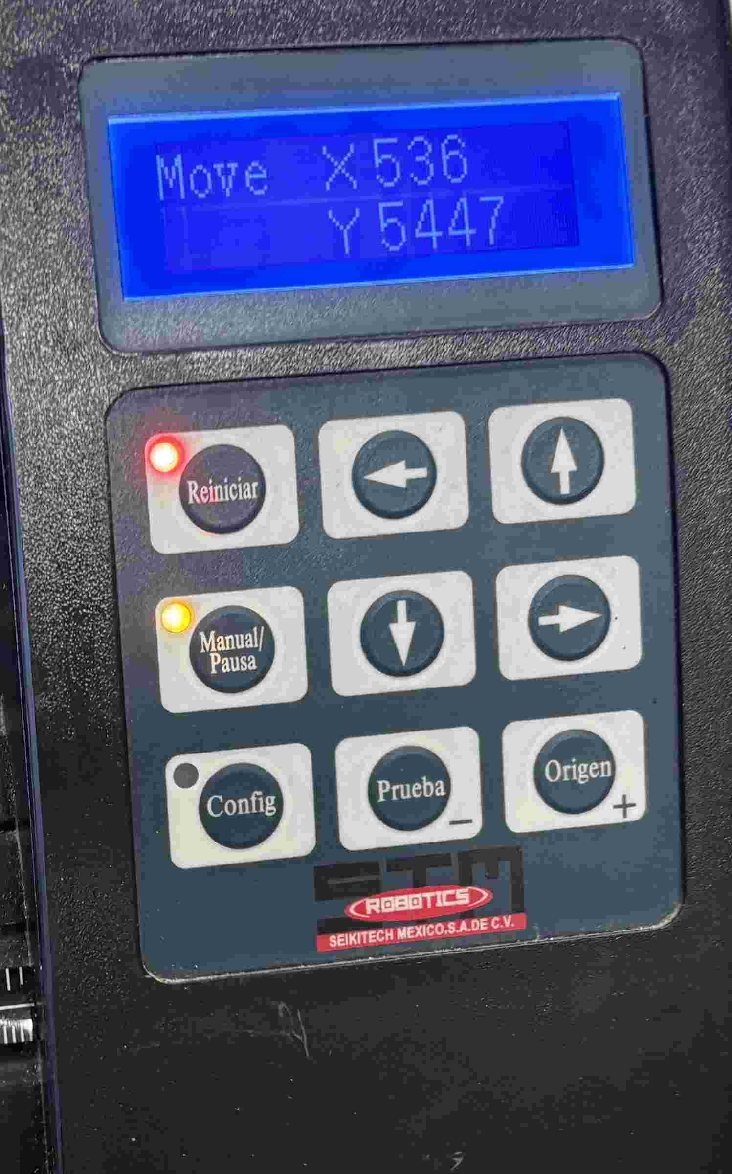
4. Setting the Origin: Move the blade to the corner of the vinyl sheet where you want the cut to begin. Press the 'Origin' or 'Set Home' button to establish the starting coordinates.
5. Signal & Execution: Verify the cut parameters in Inkscape (speed and force). Click 'Apply' in the software to send the vector data to the cutter and initiate the job.
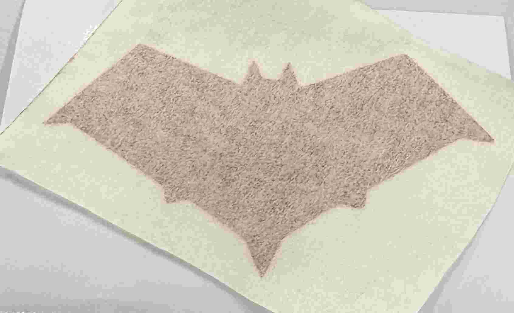
6. Weeding Process: Carefully remove the excess vinyl (the background) using a weeding tool or tweezers, leaving only your intended design on the backing paper.
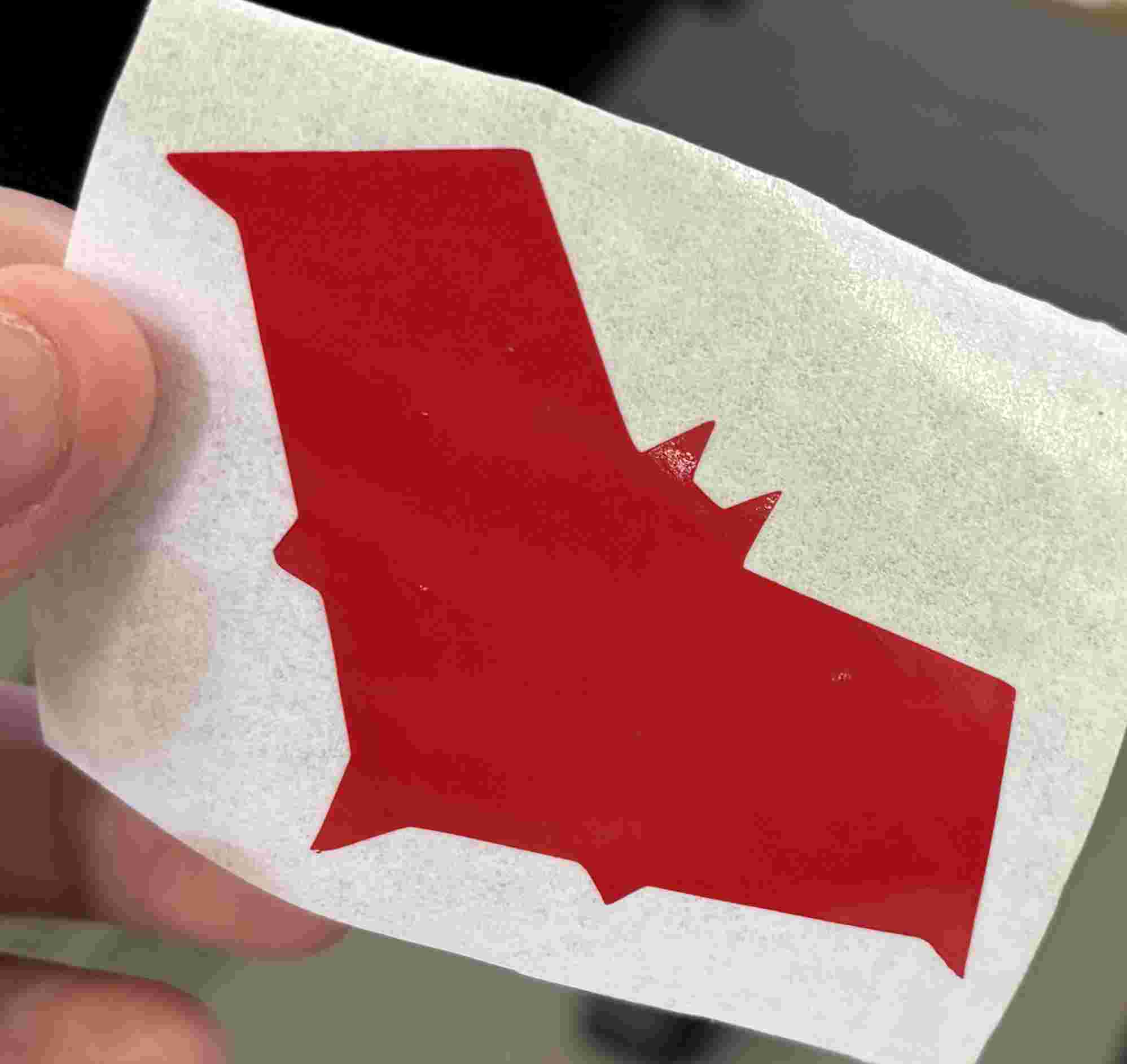
7. Applying Transfer Tape: Lay a piece of transfer paper/tape over the weeded design. Use a squeegee to press it down firmly, ensuring there are no air bubbles.
8. Peeling: Carefully flip the design and peel the original backing paper away at a 180-degree angle, ensuring the vinyl sticks completely to the transfer tape.
9. Final Placement: Align the design on the target surface. Press down firmly from the center outwards to ensure a strong bond between the vinyl and the surface.
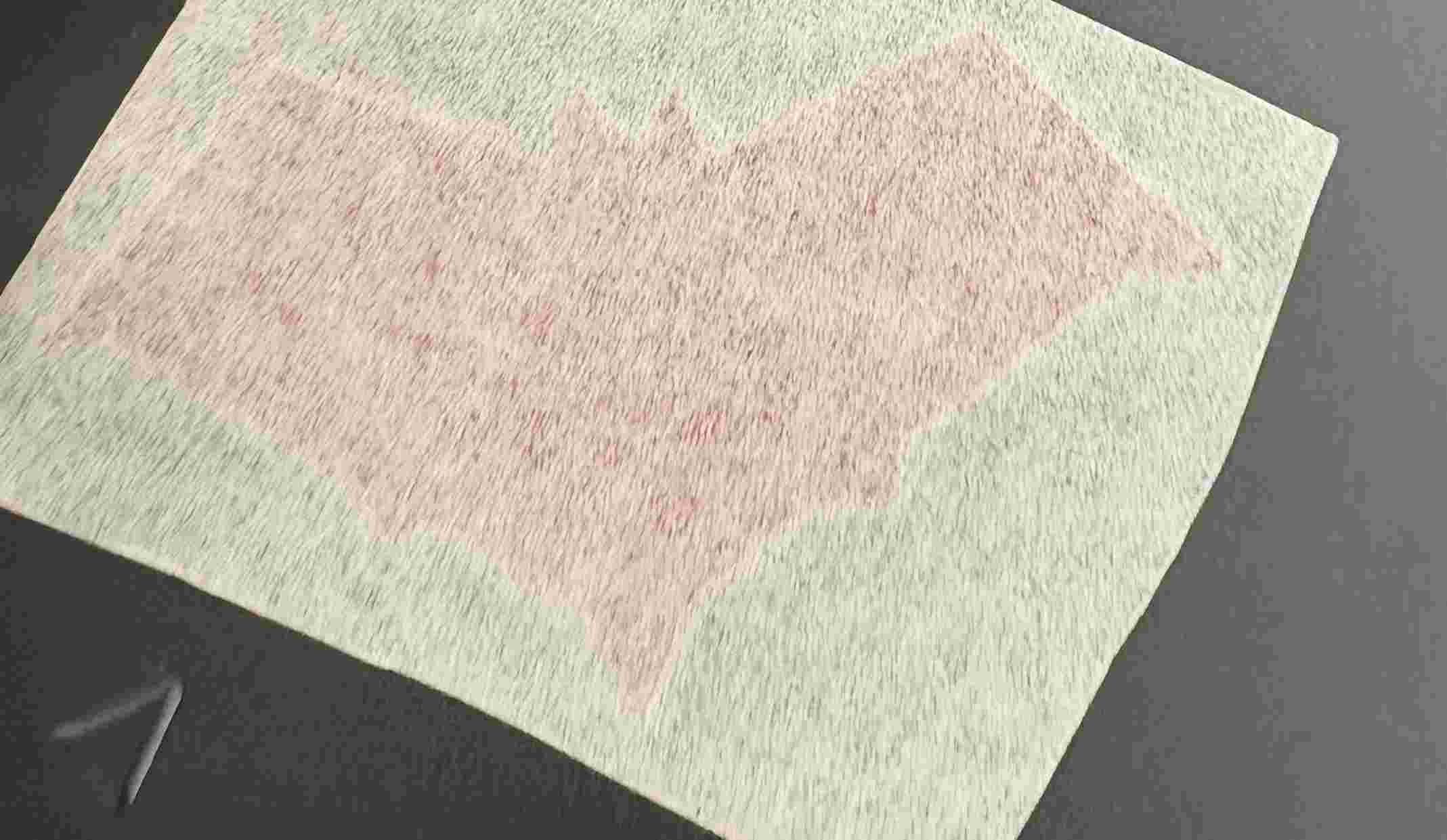
10. Finishing: Slowly peel off the transfer tape. If any part of the vinyl lifts, press it back down and rub firmly before trying again until the design is fully transferred.
This week was a valuable lesson in both design efficiency and machine troubleshooting. Mastering parametric constraints was a highlight, as it simplified the iterative process of finding the perfect fit for my laser-cut pieces. While the machine's overburning required extra attention to detail, the final results were satisfying. Combining these skills with vinyl cutting has given me a solid foundation for producing clean, professional-looking components for future projects.
Files
└── Dxf
    ├── Bisagras Laser.DXF
    ├── Circulos Laser.DXF
    ├── Pilares Laser.DXF
    └── Poligono Laser.DXF