

Week 13
Molding and Casting
Check out our Group Assignment to see everything related to safety data sheets and a casting and mold-making comparison. GROUP PAGE →
// MAIN OBJECTIVE \\
Design a mold around the process you’ll be using, produce it with a smooth surface finish that does not show the production process toolpath, and use it to cast parts.
Project description
For this week, I produced 2 molds, but each one of them was a challenge: I 3D designed and printed one mold on a resin printer, and then I created a 3D mold for a wax cube using a CNC router. After creating the positive molds, I made another type of mold, pouring silicone with the objective of making functional and reusable molds for decoration or jewelry.
3D designing and Printing
This mold is intended for jewelry. When making a 3D printed mold, we need to know a few things to ensure quality. One crucial detail is that FDM (like PLA) printing is not recommended because the minimum layer height is typically around 0.08mm. In the final casting result, those printing lines would be visible, ruining the entire project.
Because of this, you need to use resin 3D printing, which has a much finer layer height (0.05mm minimum). With this resolution, we say goodbye to visible printing layer marks on the final result.
The next thing we need to understand is locks. Locks are dead areas on the final mold that will keep the silicone stuck in certain places when you try to remove it. If there is a large lock, it won't be possible to demold, and you'd need to make a brand-new positive mold.
What is a positive and negative mold?
A positive mold is a type of mold where the figure is extruded outwards from the surface. This type of mold is mainly used for making negative molds out of materials like silicone or rubber. A negative mold has the figure indented into the surface. The way it functions is that you pour the desired casting material into it, and the final result is a fully cast 3D piece.
Once I reviewed everything, I started designing the positive molds. I used SOLIDWORKS for every design, and I decided to go with the most classic piece of cast jewelry: rings. First, I took measurements of my girlfriend's finger and mine, and then I personalized them.
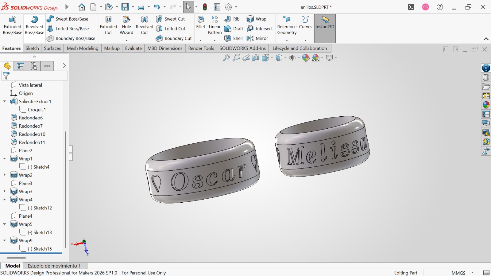
Front view of my personalized rings.
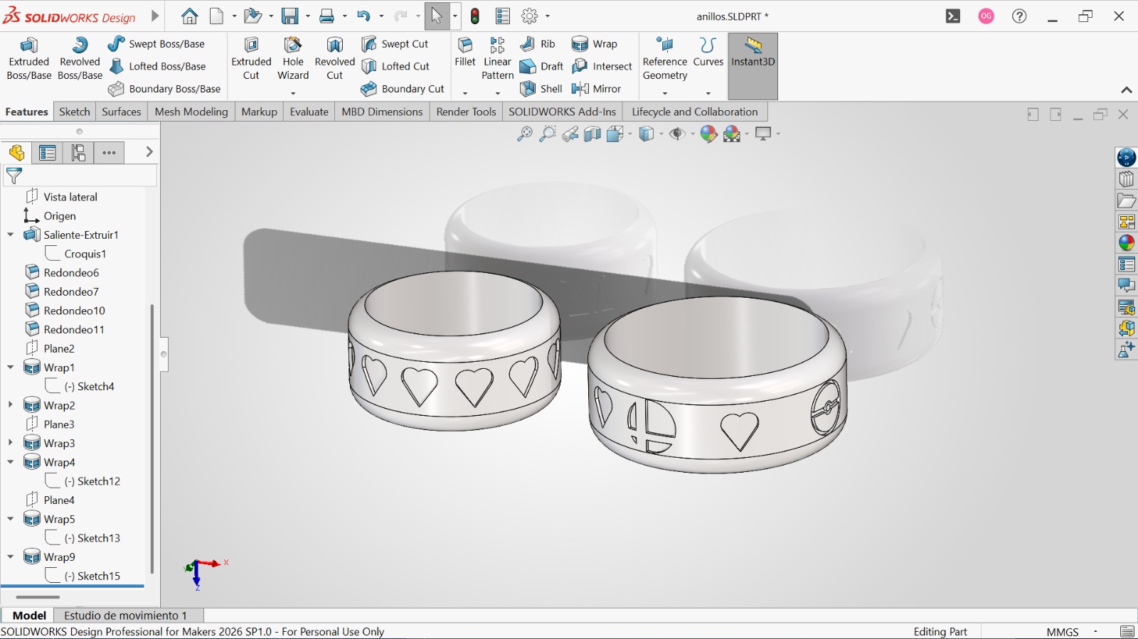
Rear view of my personalized rings.
After designing the rings, I needed to split them and make two positive molds for wax injection. To do this, I created an inlet for the wax on each ring.
NOTE:
When making the wax inlet, you need to create a cone-shaped entrance to allow bubbles to escape and to perfectly fit the nozzle of the wax injection machine.
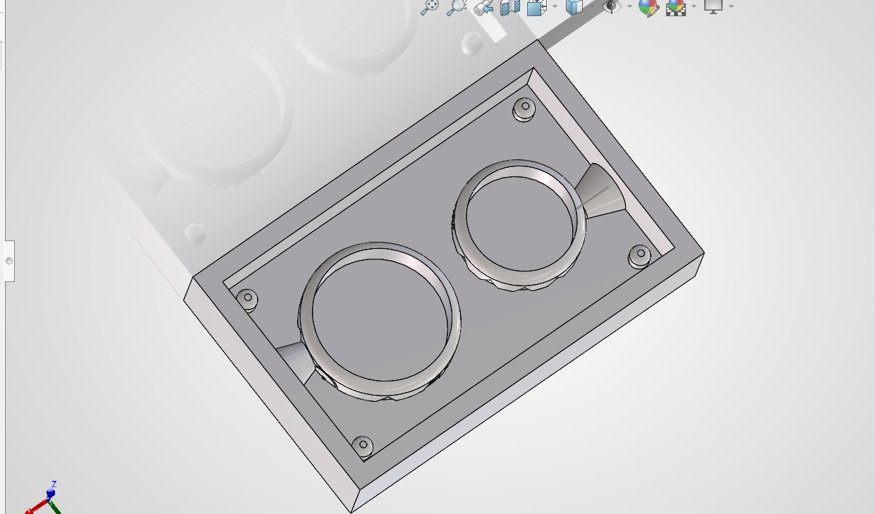
Bottom cut with cone-shaped inlets.
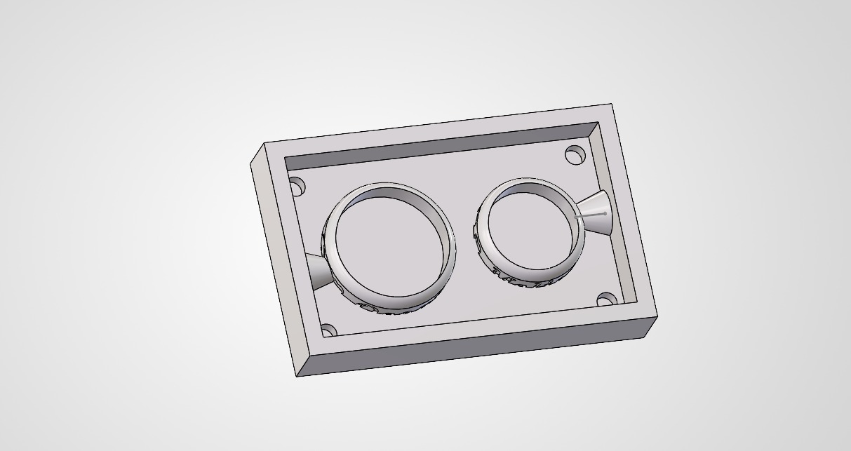
Top cut with cone-shaped inlets.
Fabrication of the resin molds
Resin printing and silicone pouring
Once the models were designed, I started the resin printing process. First of all, this is the setup of the 3D resin printer:
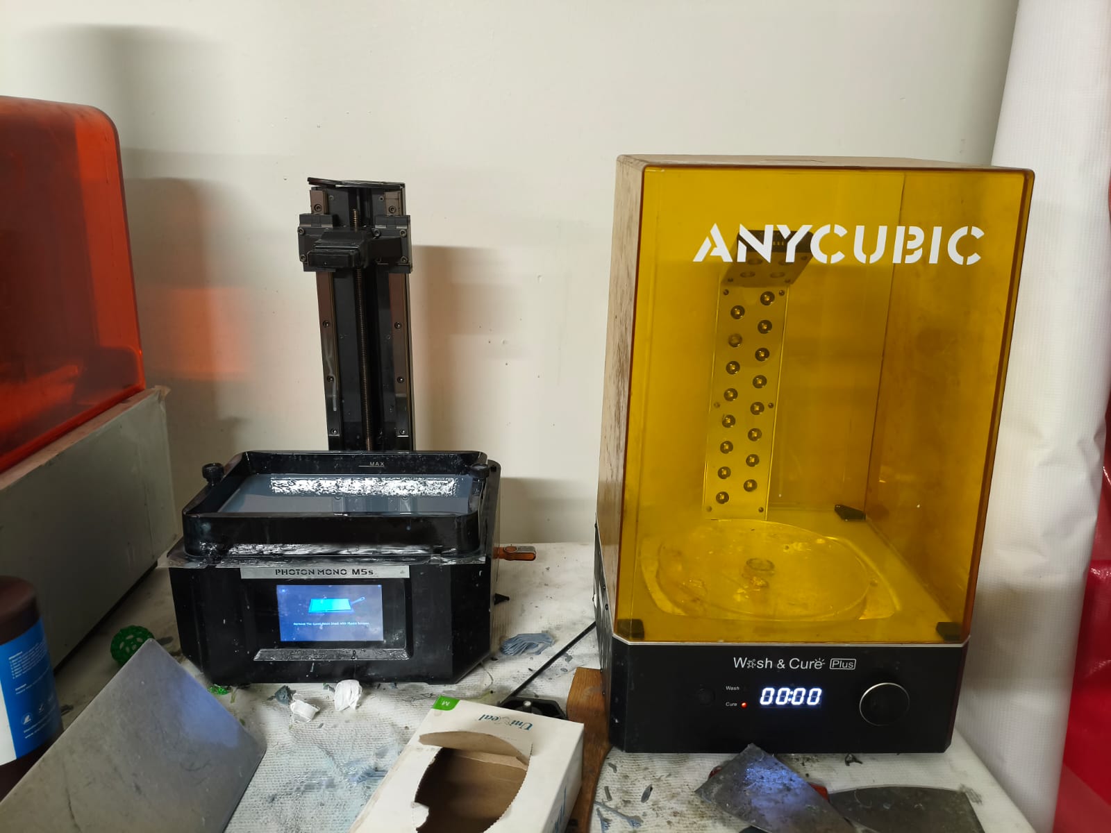
The Photon Mono M5s resin 3D printer and the curing machine.
After setting up the machine, I started to print all the positive molds:
Process of 3D printing.
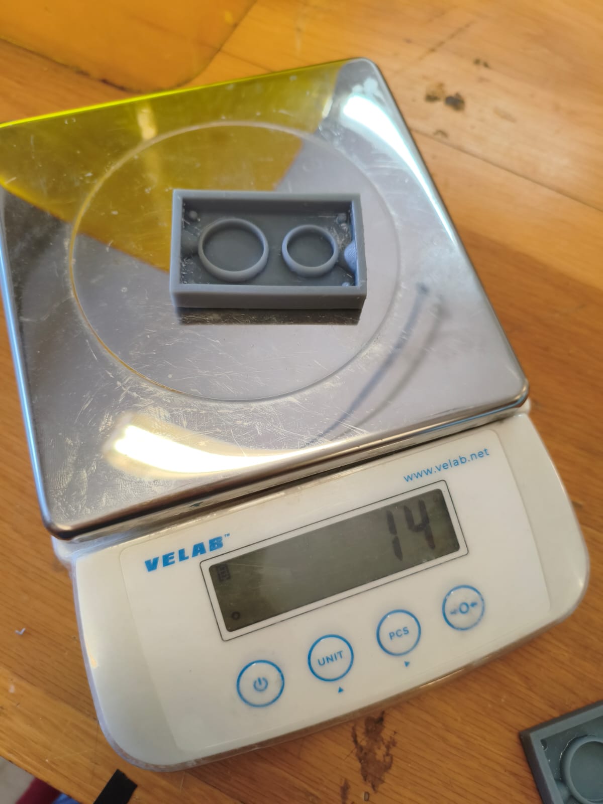
Final result and weight of the 3D printed molds.
Designing and fabrication of the wax mold
I decided to do an extra task for this week because I enjoyed the process so much. It consists of a positive mold made out of wax. This is made by roughing two 88x75x38mm wax blocks with the CNC router we used in previous weeks.
First, I used the same technique as the ring molds, but adapted it to the size of the block, making a much larger inlet since we won't be using the wax injector.
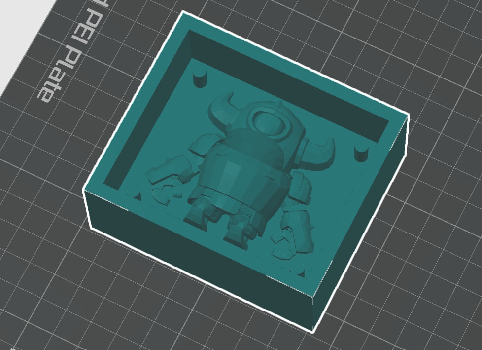
Top half of the 3D designed mini PEKKA mold.
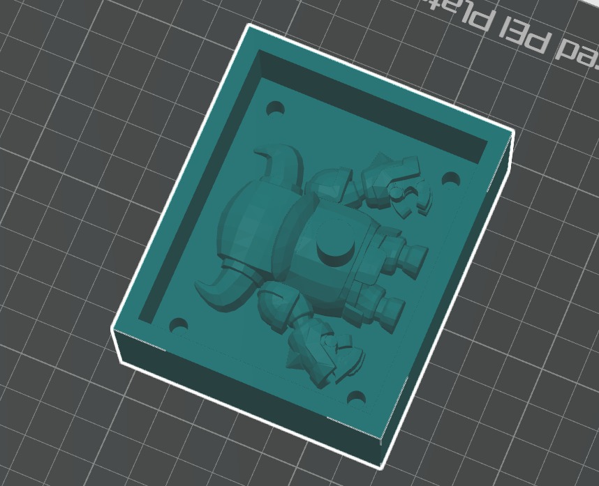
Bottom half of the 3D designed mini PEKKA mold.
After that, I imported the files into the router program. First, I defined all the parameters on the initial list that pops up once you import a model. Then, it's necessary to set the proper end mills for roughing and detailing.
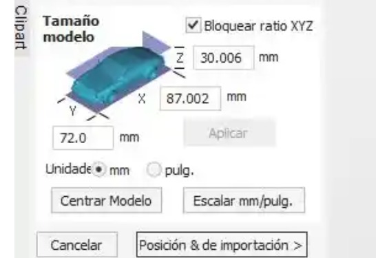
Changing wax block parameters.
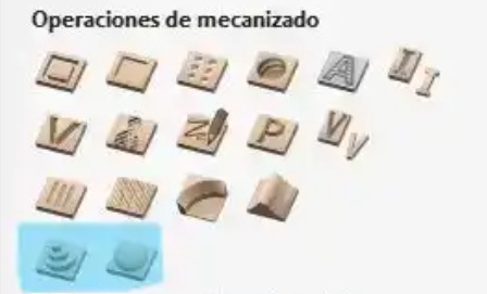
Roughing and detail tools (left roughing).
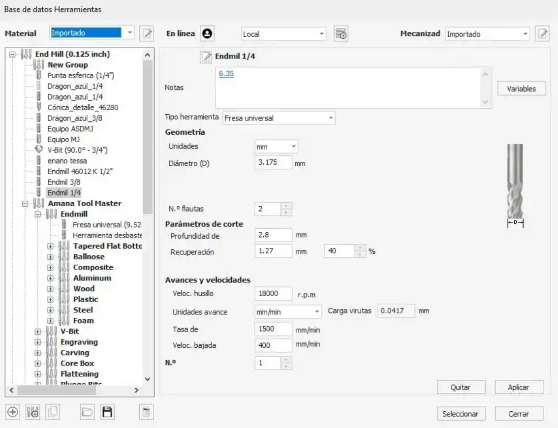
Roughing tool parameters.
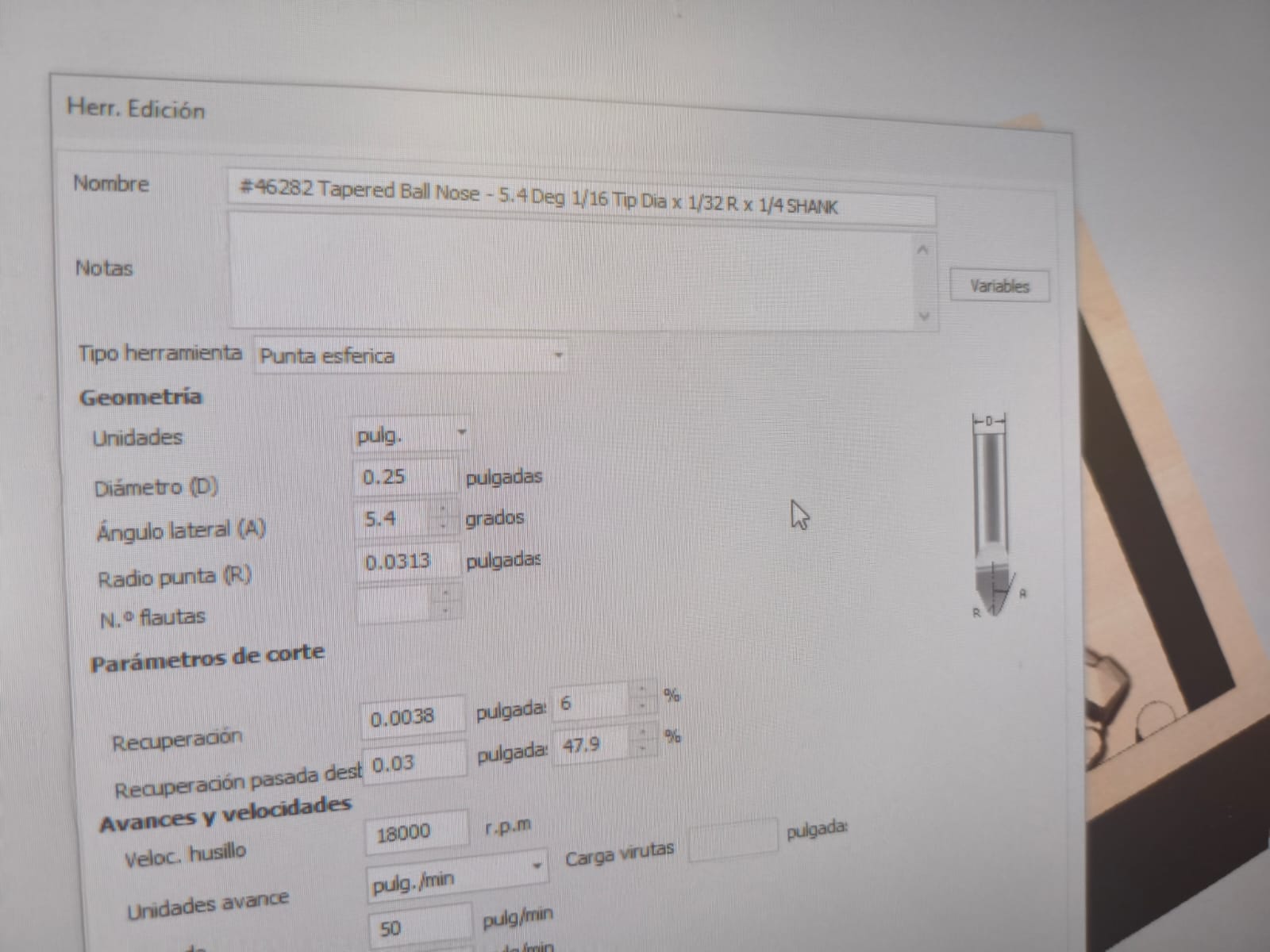
Detail tool parameters.
After setting all the parameters, we need to select the roughing tool to run a simulation of the machined block. This is the result:
Simulation of the roughing process.
Just like with the roughing, I needed to run a simulation with the detailing tool.
Simulation of the details after roughing.
Making the wax mold
After saving both files for the CNC, it's time to use the machine to make the mold. First, we need to secure the block completely to avoid accidents.
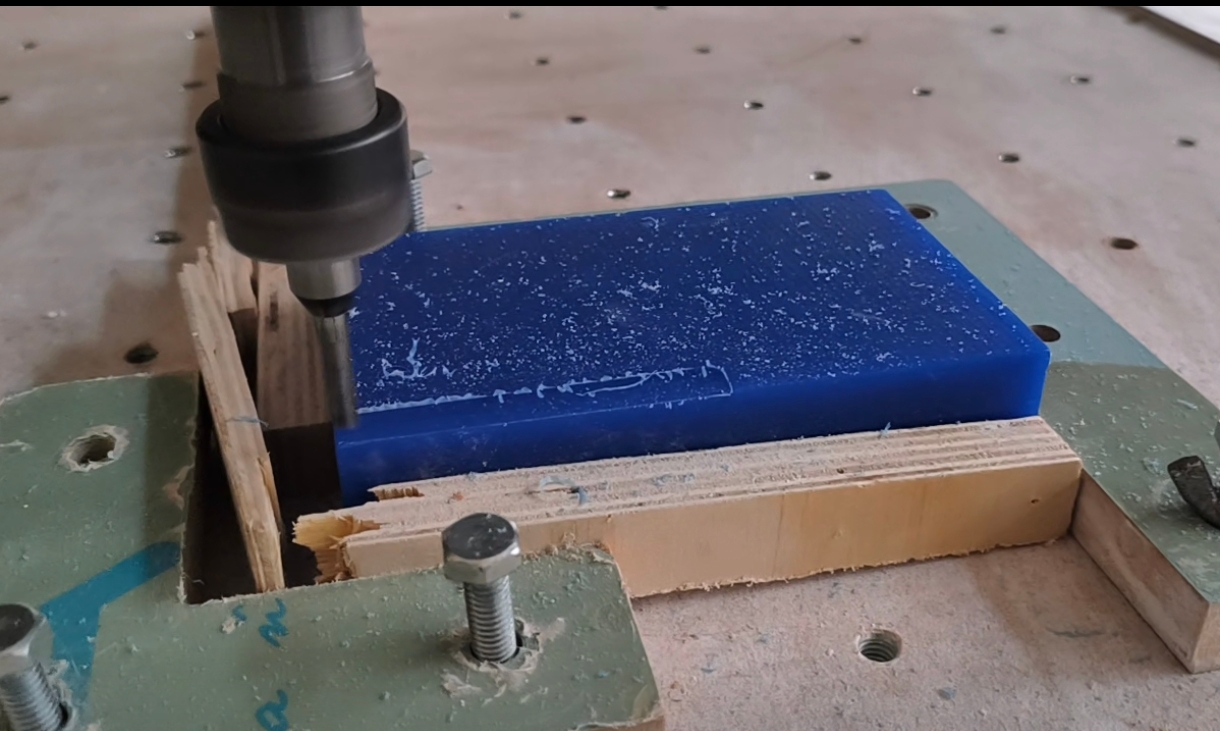
My setup for fixing the block.
After that, you need to load the correct end mill into the machine and set the zero point on all axes.
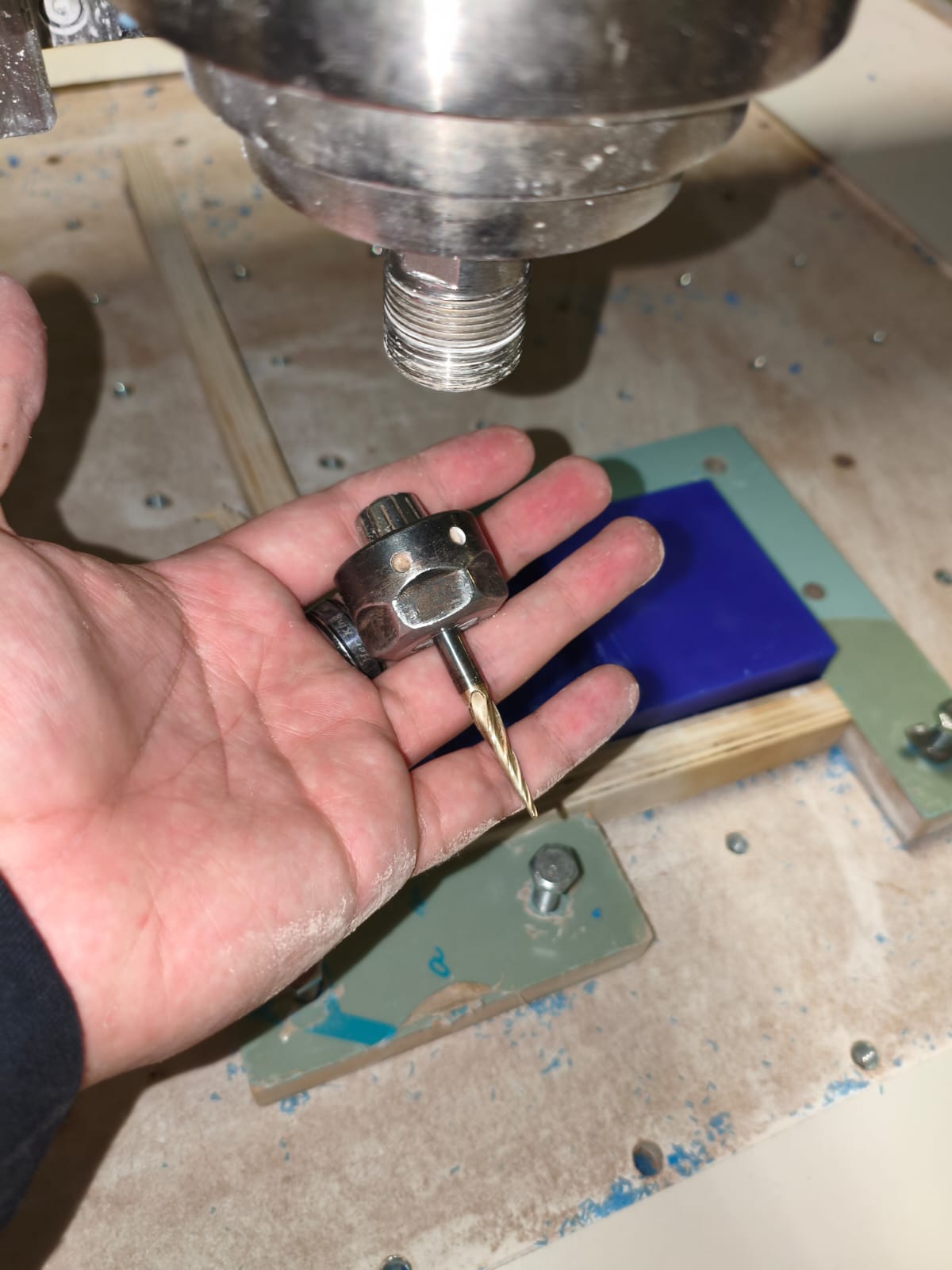
Milling setup.
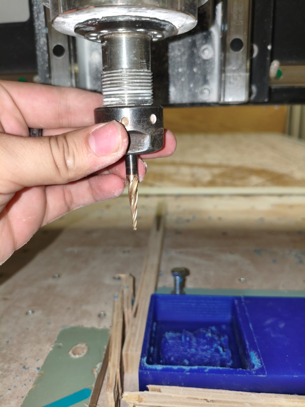
Checking the position of the end mill and setting zeros.
After that, the only thing left to do is press play. While it is roughing or detailing, you need to use the vacuum to get rid of the wax flakes, which are useless and might cause deformations if left on the piece.
Roughing and adding details to the mold.
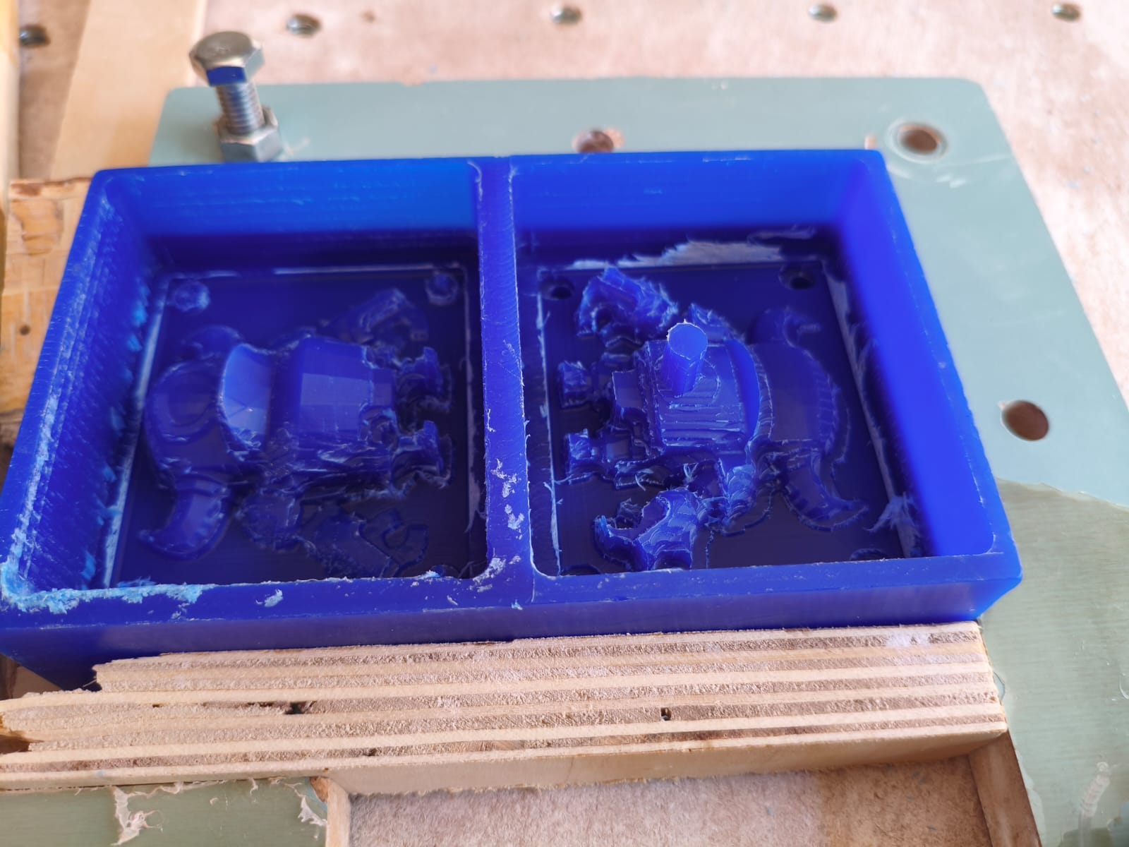
Difference between a roughed and a detailed mold.
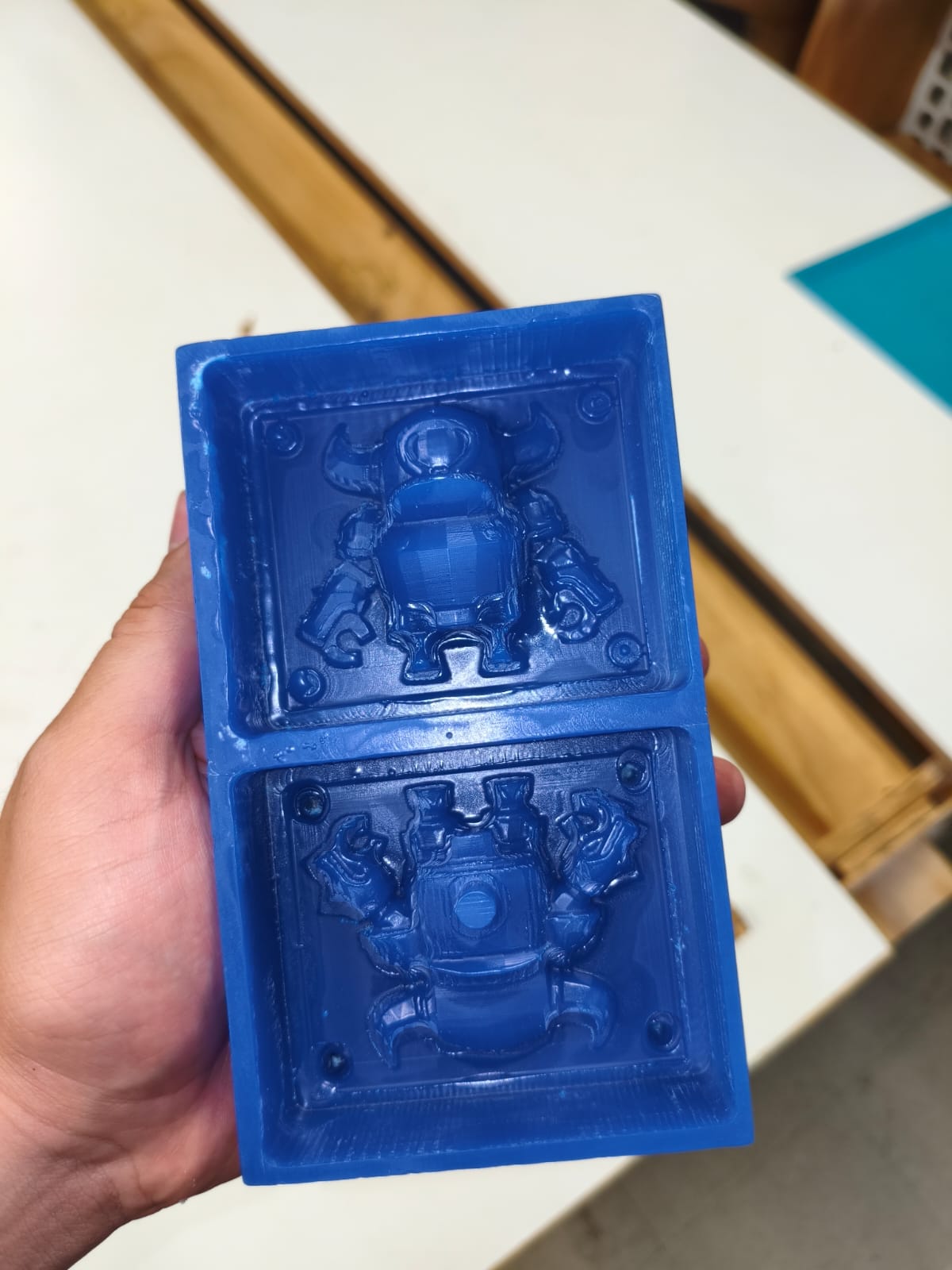
Final mold result.
Now for the most important part...
Silicone pouring
Now it's time to do the casting part. We need to use the 30/30 silicone with its catalyst. We used this one:
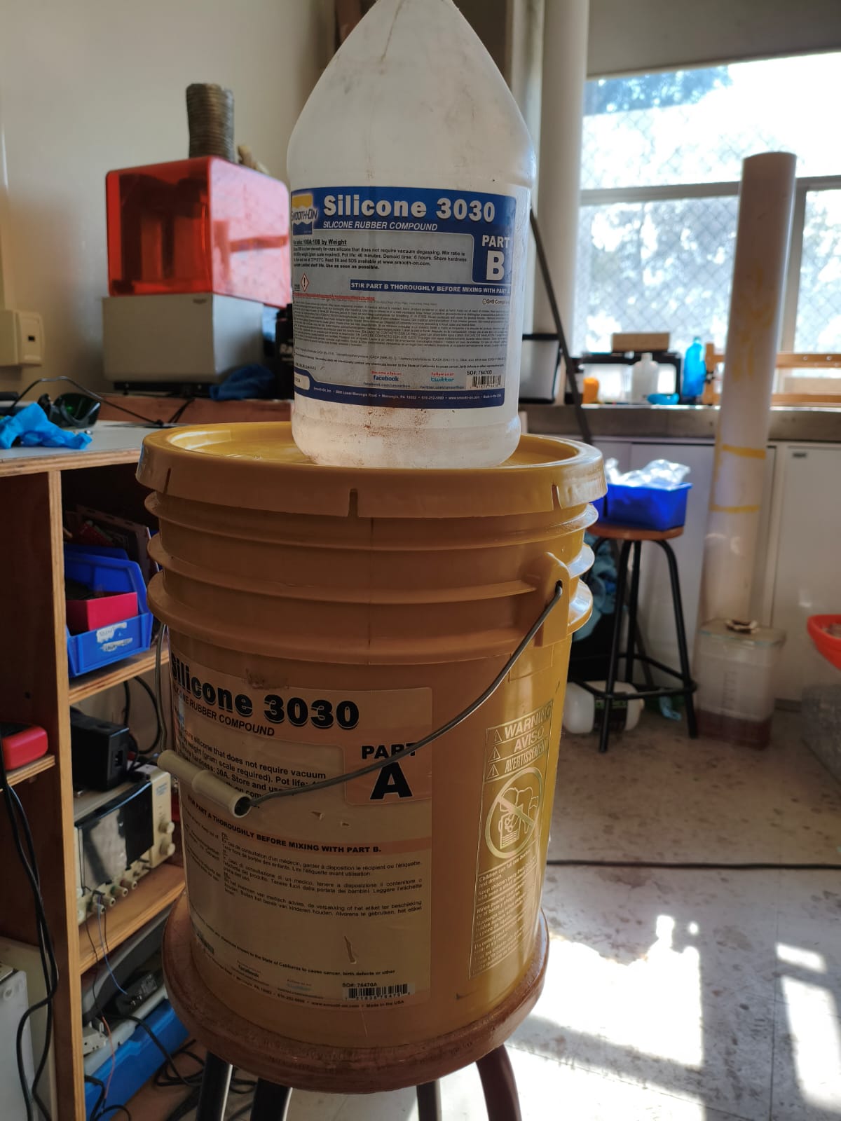
The silicone and catalyst that I used.
The ratio of silicone to catalyst is 100/10, which means 100 grams of silicone requires 10 grams of catalyst to cure properly.
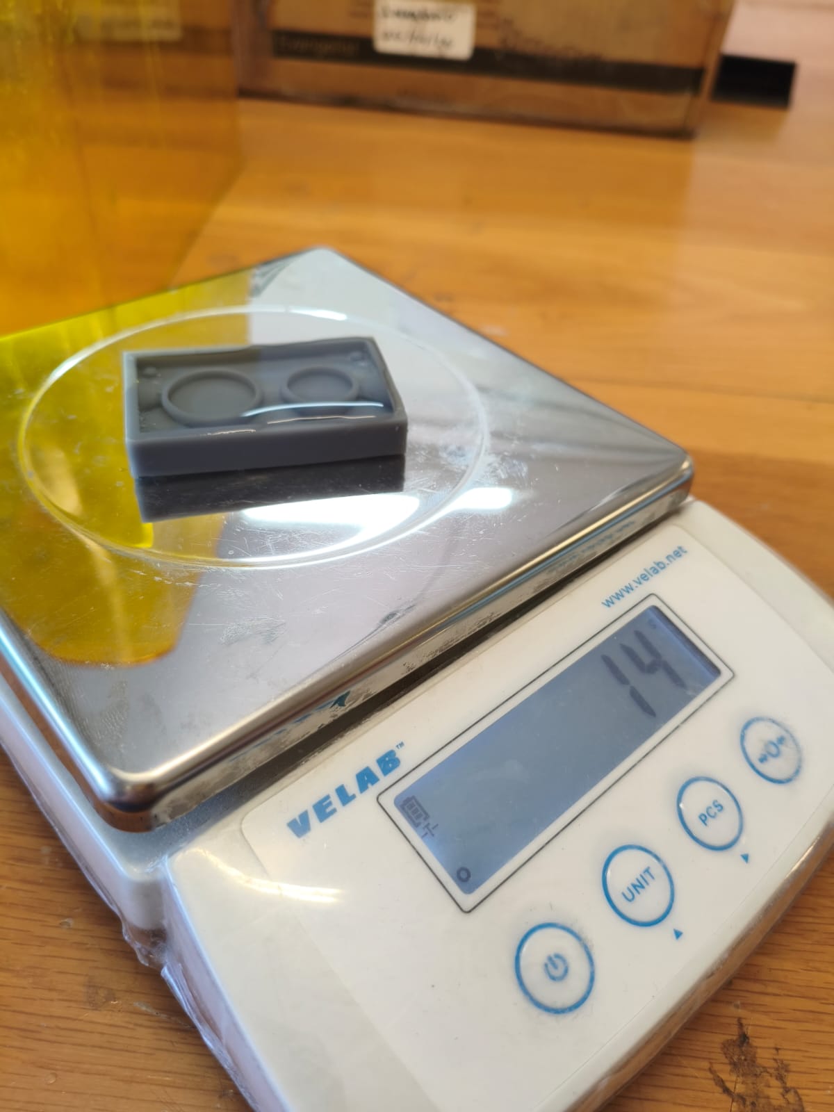
Calculating the volume of the mold with water (I used 20g of silicone).
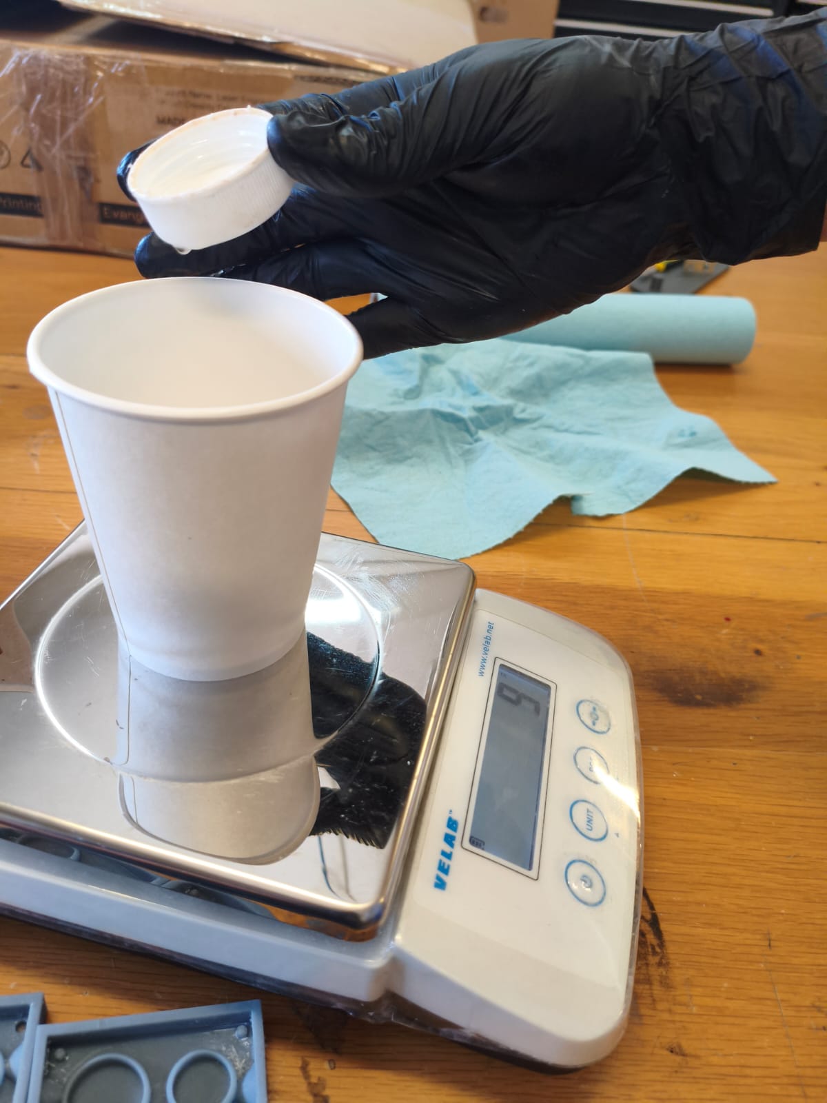
Calculating the required amount of catalyst.
Once I had all the materials ready, it was time to work quickly. We need to use the vacuum chamber to extract all the bubbles.
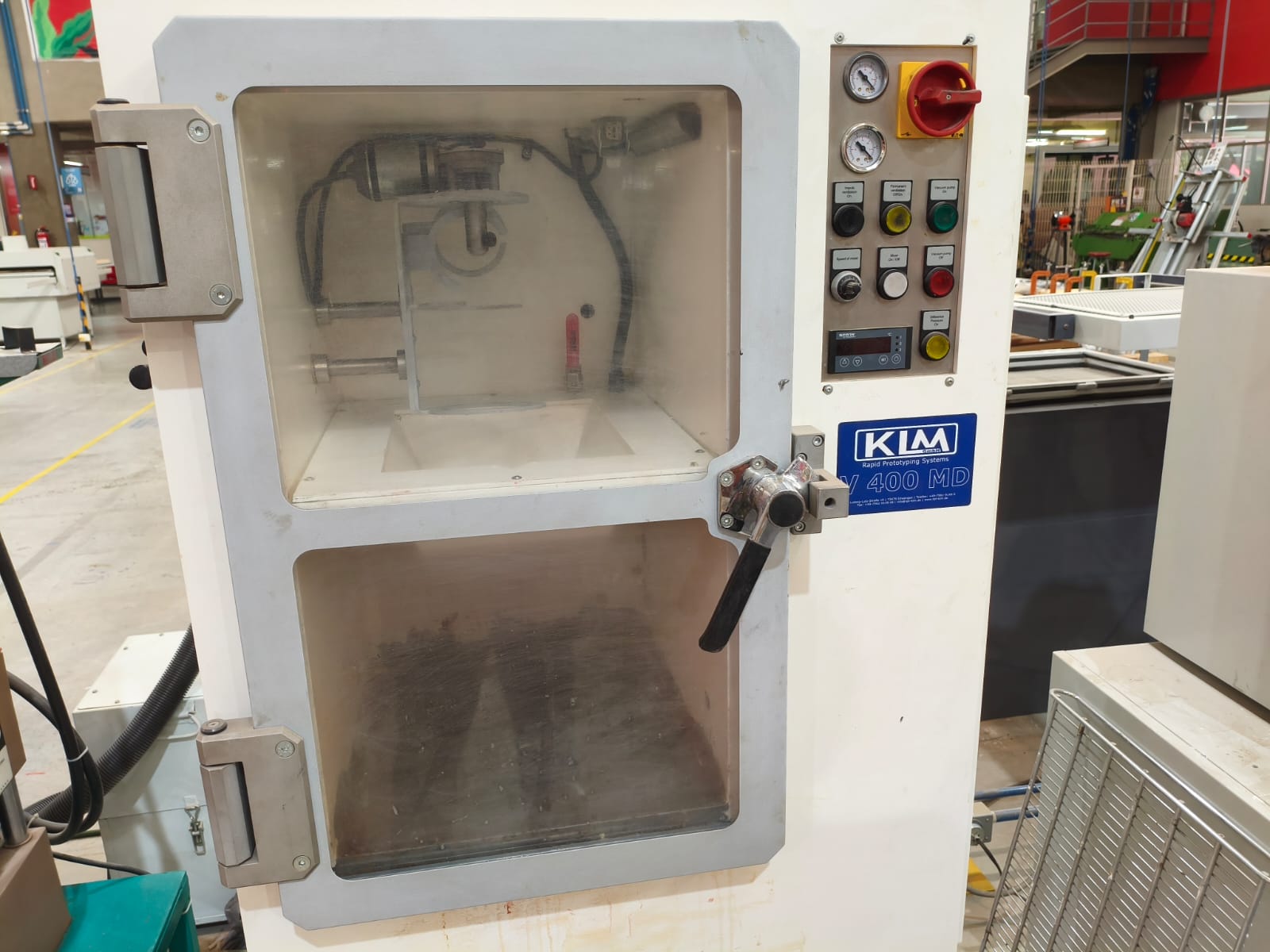
The vacuum machine.
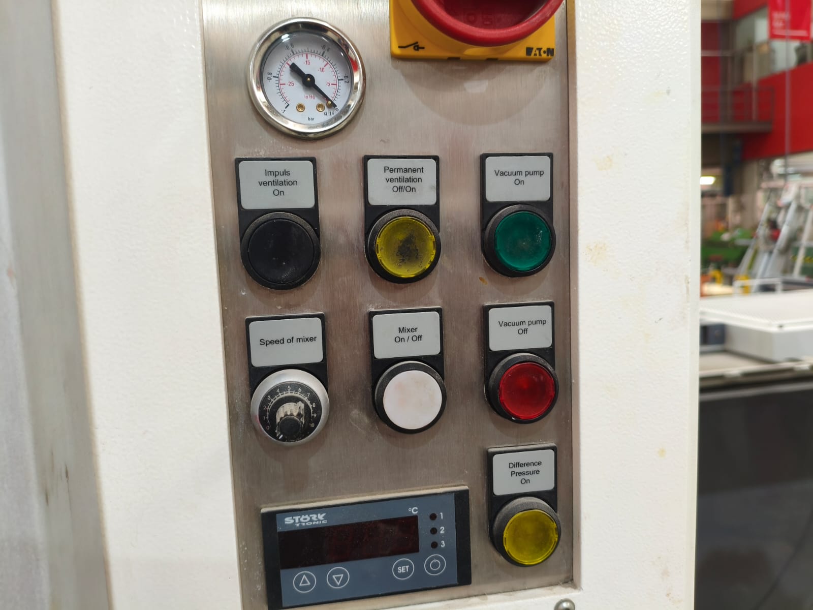
Close up of the control buttons.
To make a high-quality mold, we need to follow these steps:
- First, mix the silicone and its catalyst thoroughly. After doing this (with this specific type of silicone), you have about 3 minutes to pour the mixture into the positive mold. If you take longer, the mixture will become more viscous and trap bubbles in the final negative mold, ruining the entire project.
- After mixing, quickly place it in the vacuum machine. Leave it for about one minute to pull out the bubbles, then turn everything off and take the mixture out.
- Next, pour the mixture into the mold from high up, creating a very thin stream so it reaches all the small details. Then, shake the mold gently to release any trapped bubbles and ensure the silicone flows everywhere.
- Finally, depending on the size of the mold, wait 4 or 5 hours to let it cure before demolding.
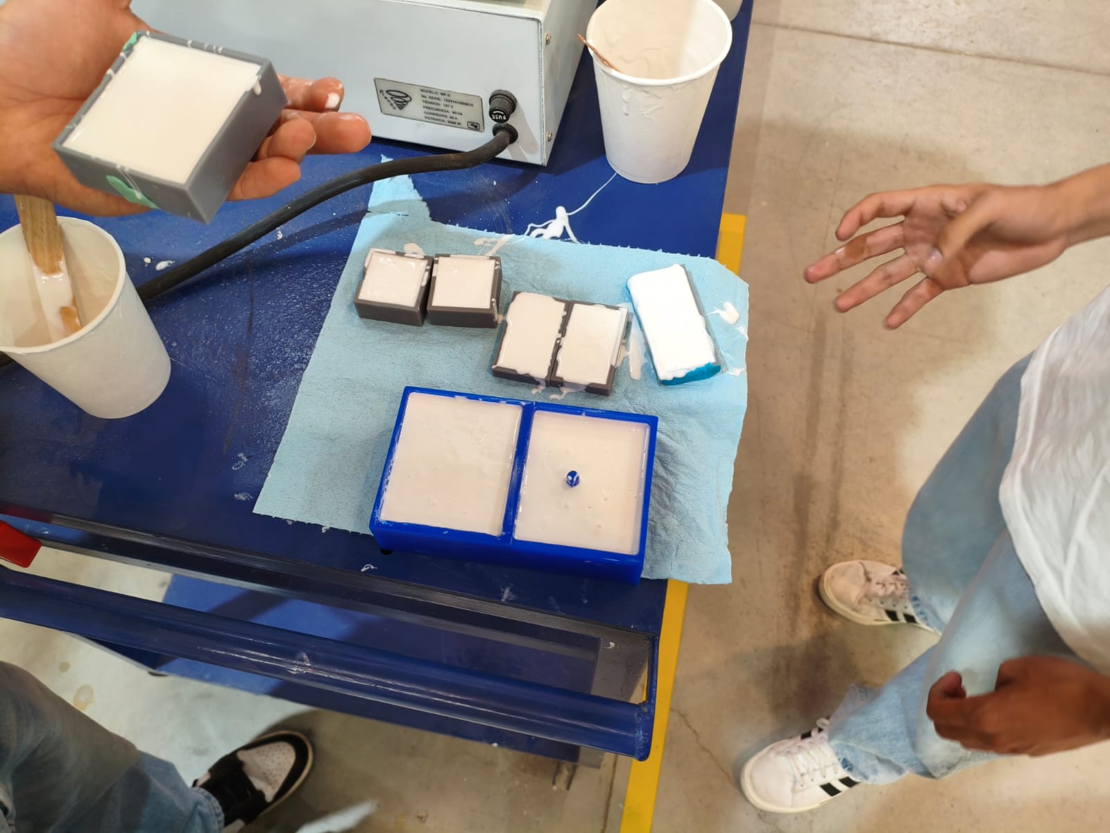
The entire silicone pouring process.
After waiting...
Demolding the final result.
The molds resting.
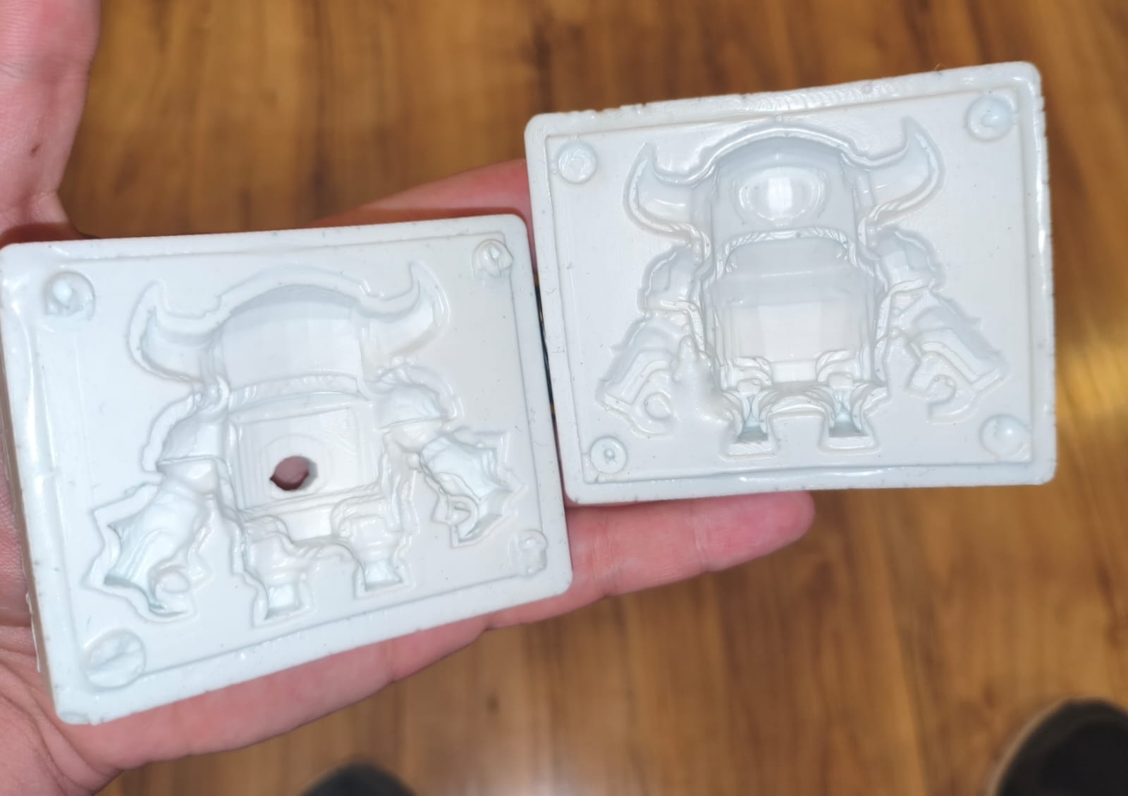
Mini Pekka final mold result.
Results and applications
After finishing both molds, I needed to test them by casting some wax. In my Wildcard Week, I'm going to be using the wax injector I mentioned before, but this time, my partner and I used a syringe to manually inject candle wax melted in a water bath.
When injecting or pouring wax into a two-part mold, you need to secure both halves tightly. The most professional method is to make a press using two pieces of MDF or similar material held together with screws, which completely prevents deformation. Another way is to use rubber bands, but this only works well for large, simple molds that don't require high-pressure injection. Using rubber bands on the ring molds, for example, would definitely cause deformation and leaking issues.
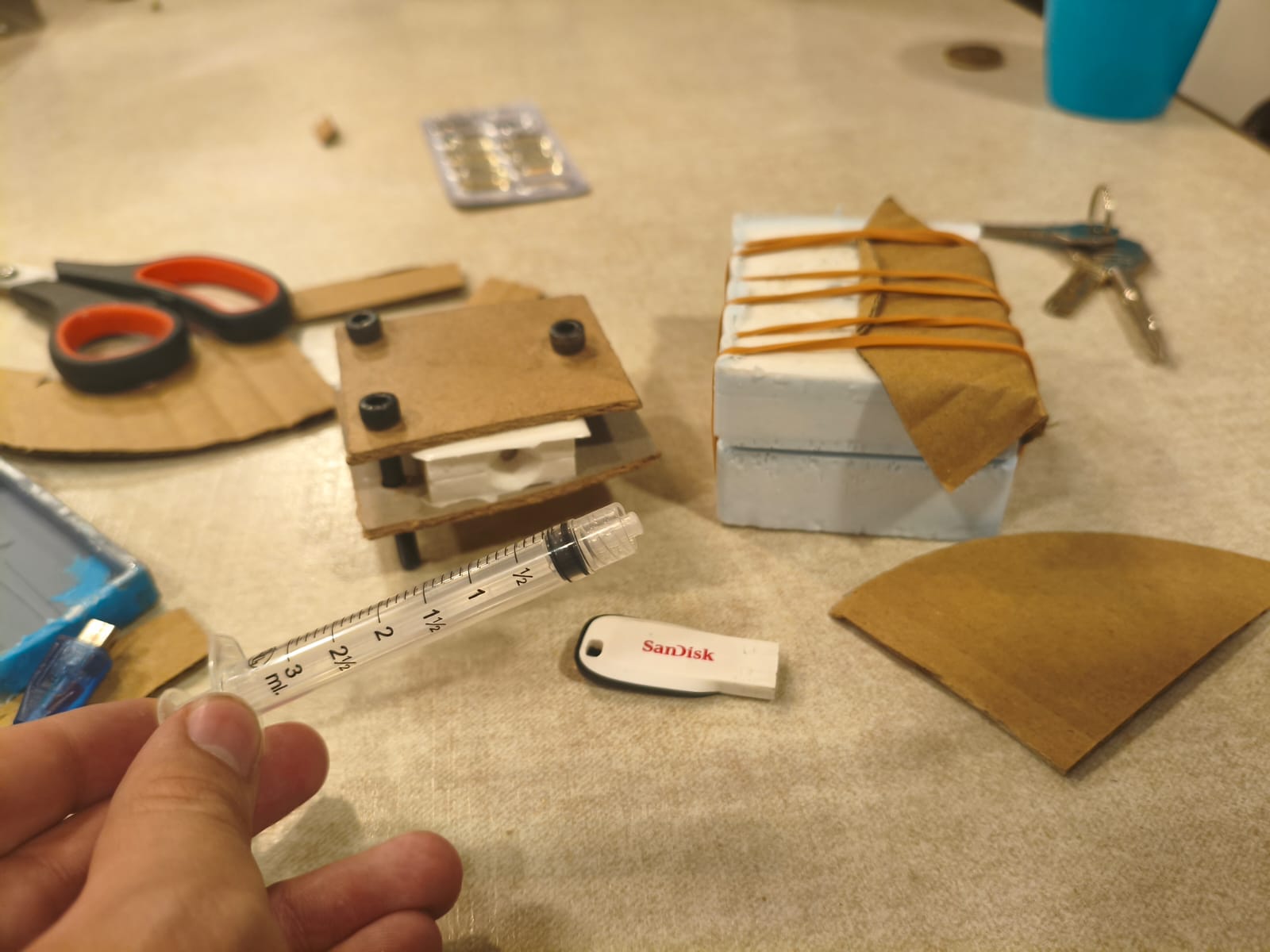
My wax pouring and injecting setup.
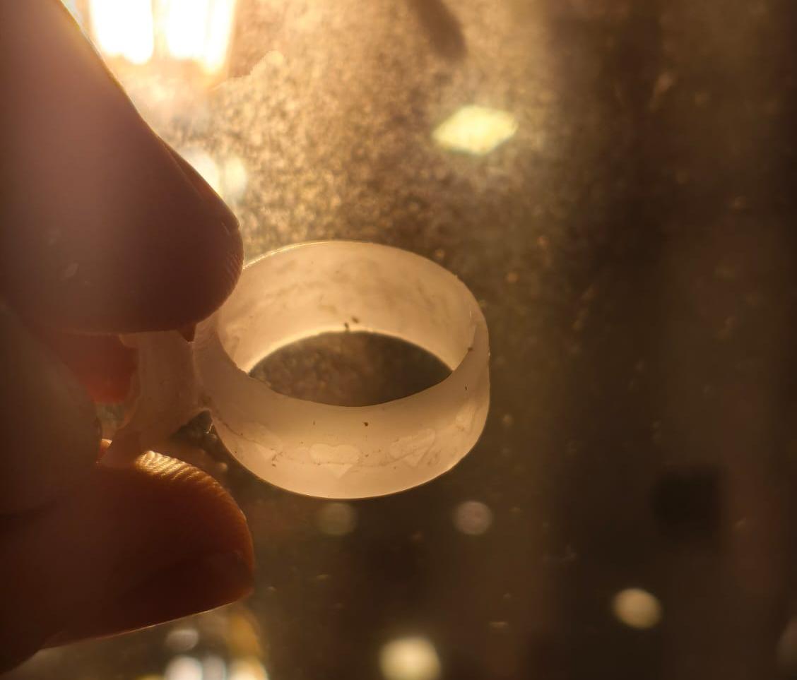
My final ring wax cast with details.
Mini Pekka wax mold final result.
This was one of the most satisfying weeks in my personal opinion. In my Wildcard Week, I will be continuing this process to make wearable silver rings for my girlfriend and me.
Files
Here you can download the original STL files generated for this week's project: