

Week 07
Computer-Controlled Machining
// MAIN OBJECTIVE \\
The challenge for this week is to design, implement CAM toolpaths, and manufacture a large-scale project—specifically, a piece of furniture—using a large format CNC router. I will focus on the design flow in SolidWorks, preparing images for special engravings with Krita, and generating toolpaths in VCarve Pro, including essential techniques like dogbones and holding tabs for a successful cut.
If you want to see our Group Assignment regarding safety and machine testing for this week, click HERE →
Safety Training Reflection
Before operating the large format CNC router, we underwent mandatory safety training. I learned the importance of wearing proper personal protective equipment, including safety glasses and hearing protection. Understanding the location of the emergency stop button, never leaving the machine unattended while cutting, and properly securing the stock material to the bed are critical steps to prevent accidents.
Design in SolidWorks
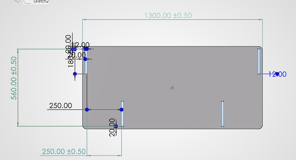
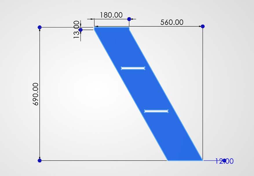
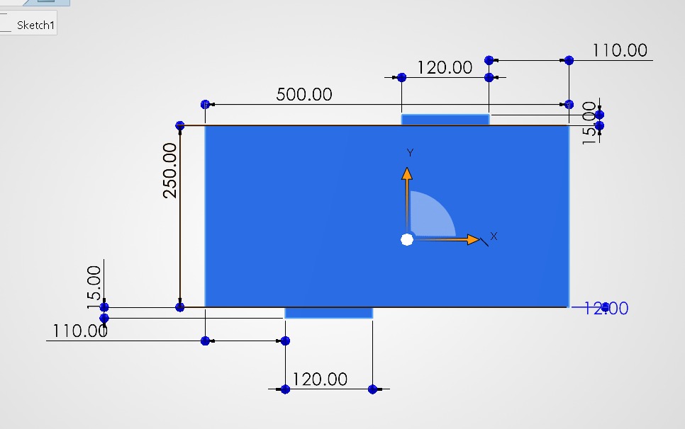
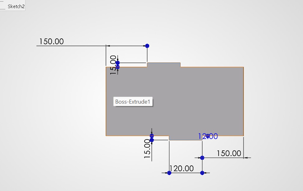
To design the furniture, I used SolidWorks. The process involved creating parametric sketches, extruding parts, and verifying assembly joints. Here is the visual breakdown of the design phase:
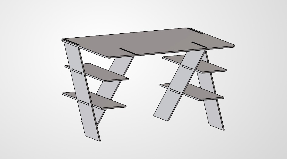
The assembly simulation made in SolidWorks.
Exporting to DXF
Once the 3D design was complete, I needed to convert the 3D faces into 2D vectors for the CNC software. I created a drawing from the part, placed the faces flat, and exported the result as a DXF file, which is the standard format accepted by VCarve.
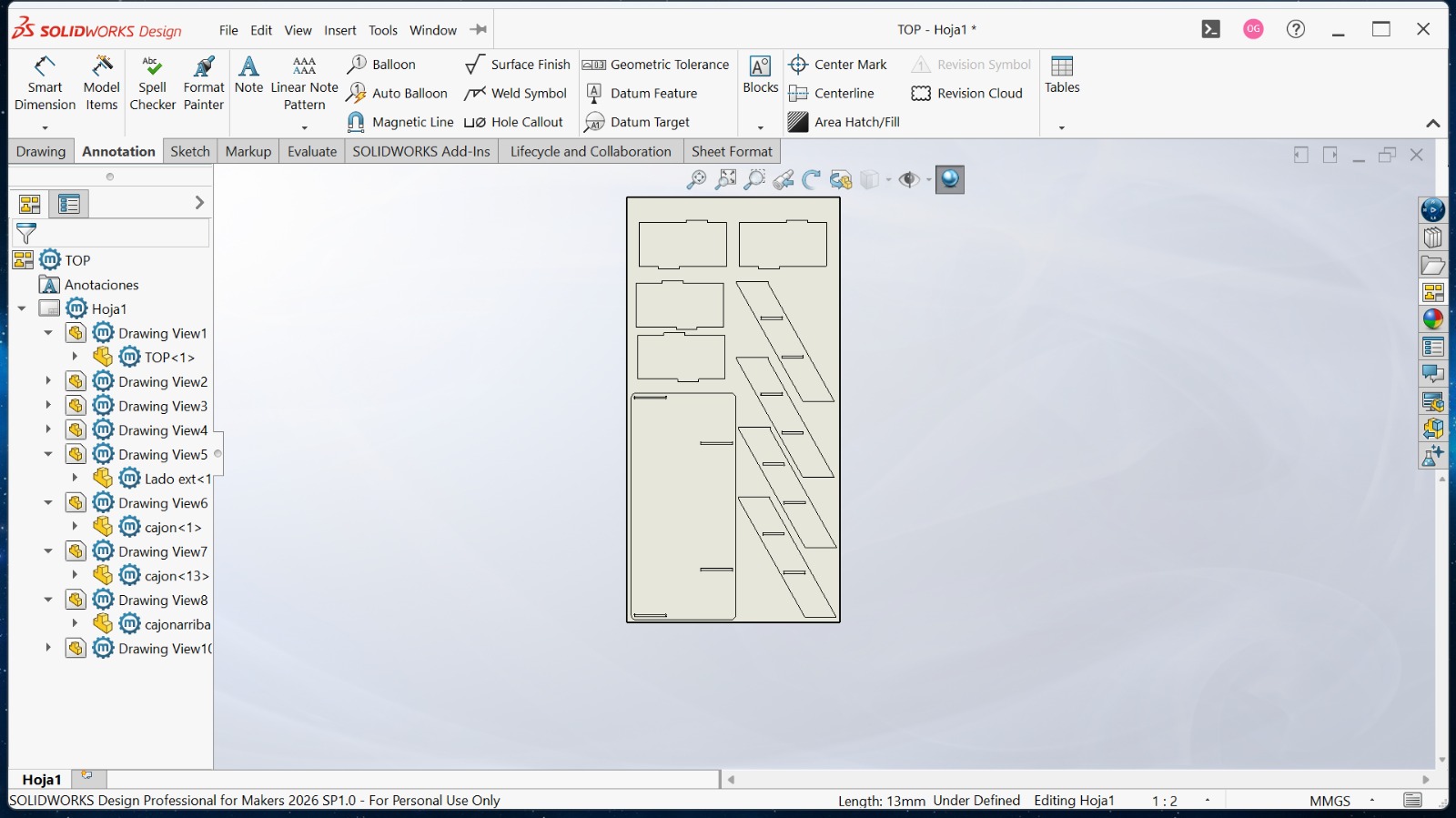
Process of creating a flat layout and exporting all components to a single DXF file.
CAM Workflow: VCarve Pro
I used VCarve Pro → to prepare the manufactured toolpaths. This software takes the 2D vectors and converts them into G-code that the CNC router can understand.
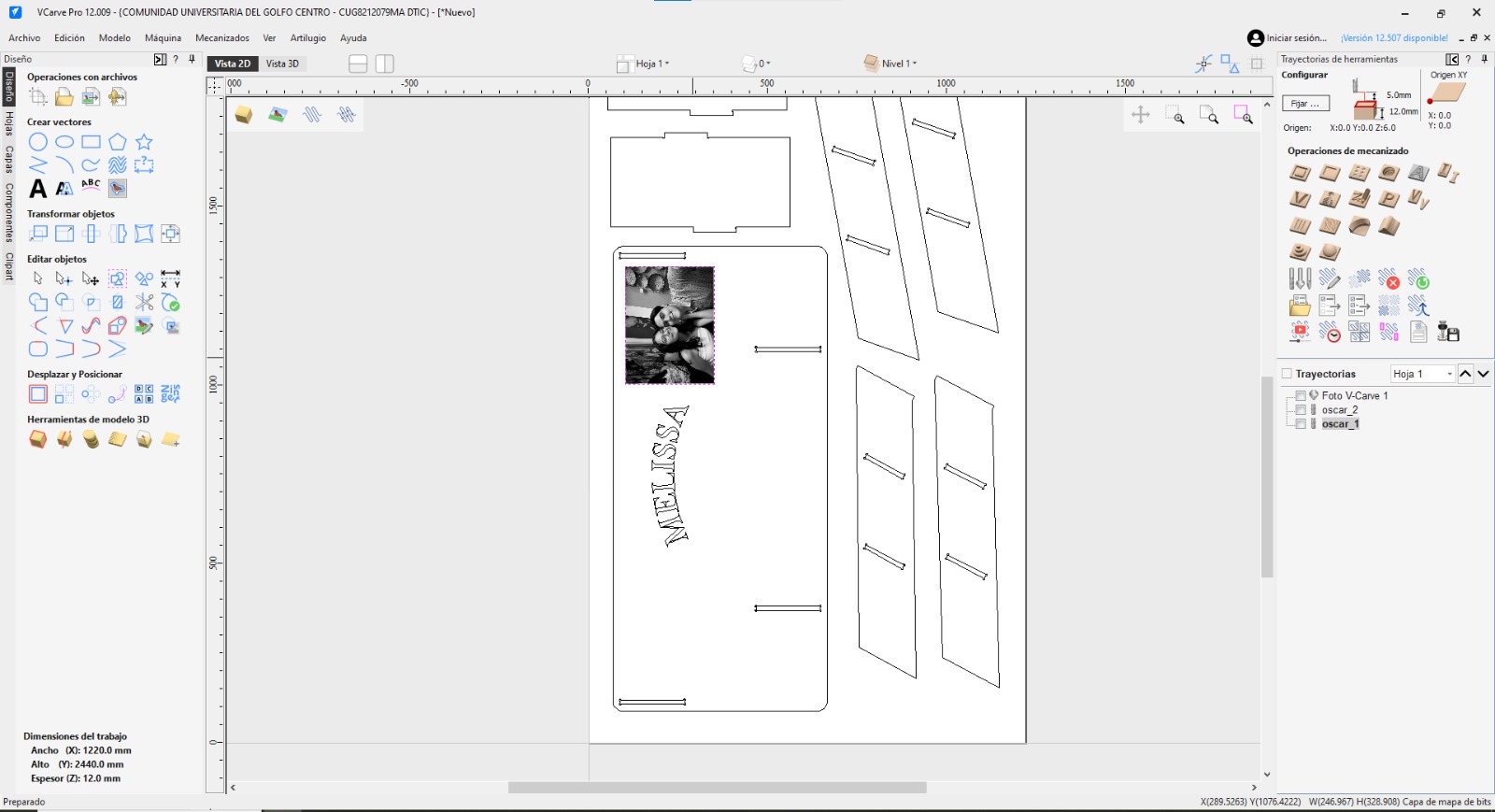
The Interface
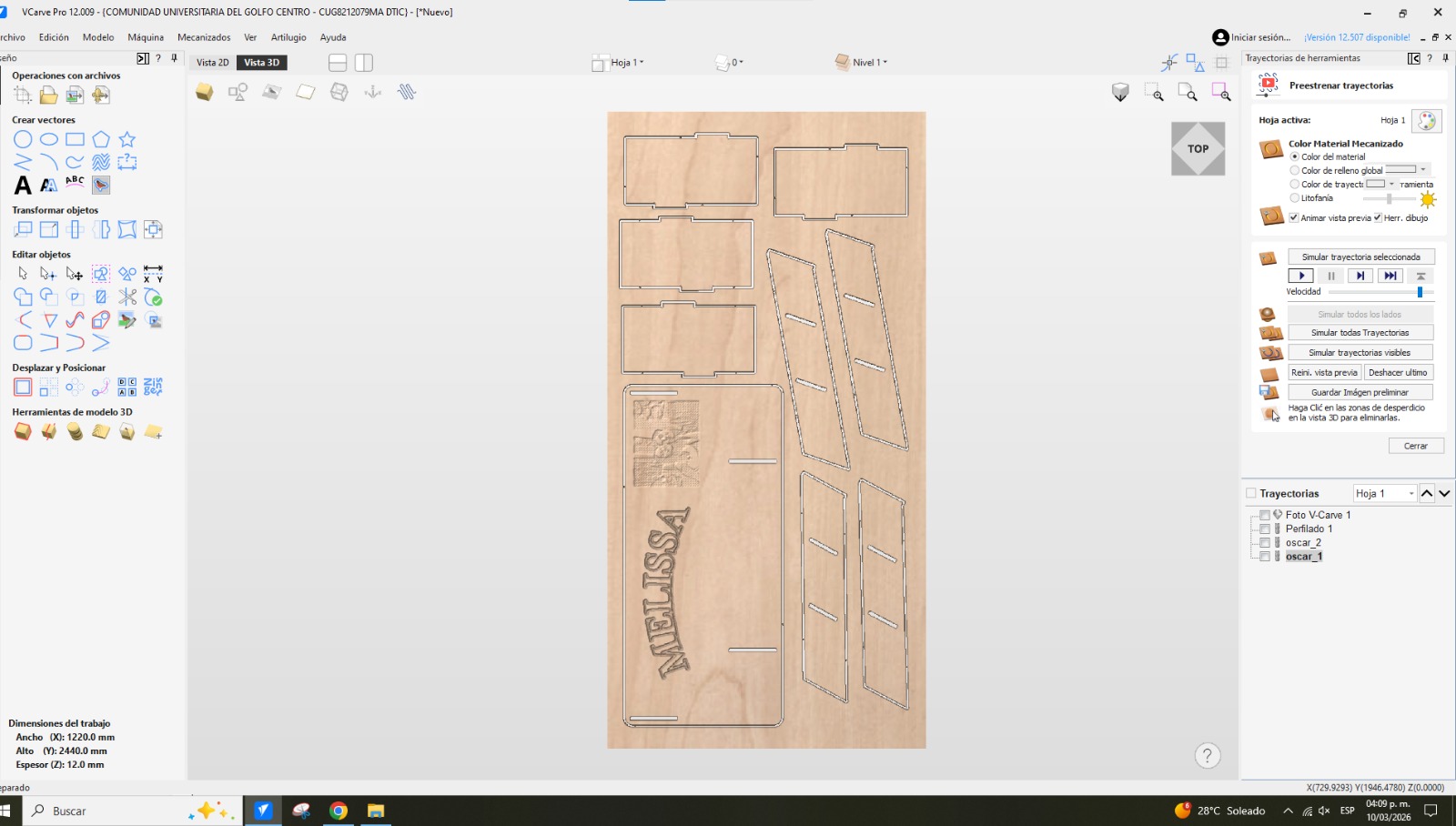
The VCarve interface is highly intuitive. It is divided into design tools on the left and toolpath operations on the right. Switching between the 2D draft view and the 3D simulation view is essential for verifying how the job will be cut.
The VCarve Pro interface, showing the vector layout of the furniture parts.
Importing the Vector File
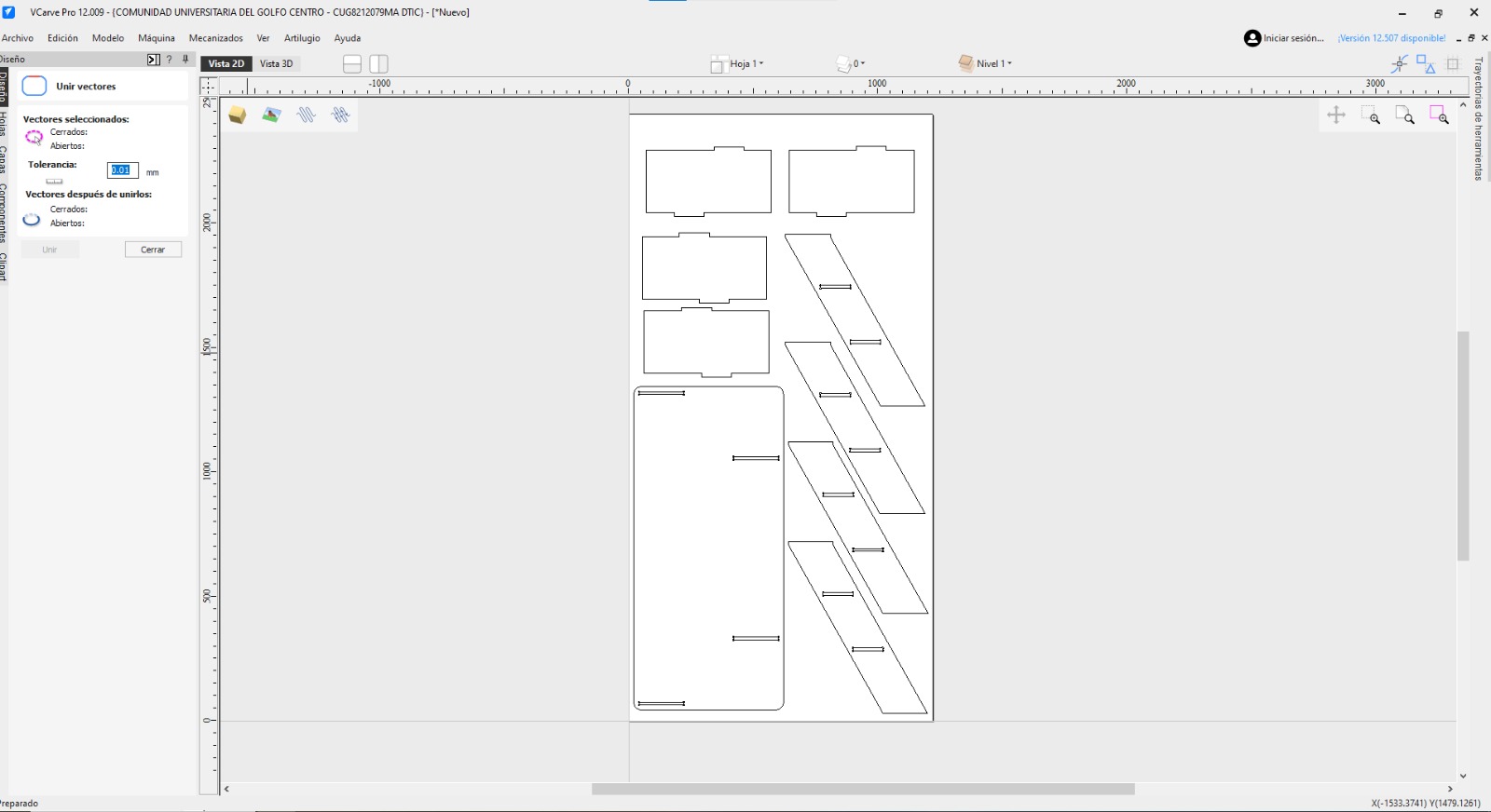
Importing the generated DXF.
Essential Cutting Techniques
Implementing Dogbones
CNC routers use round bits, meaning they cannot cut sharp internal 90-degree corners. To allow square tabs from other pieces to fit into these slots (a "press-fit" or "slot and tab" joint), we must apply "dogbones". These are small circular over-cuts at the corners that compensate for the tool's radius.
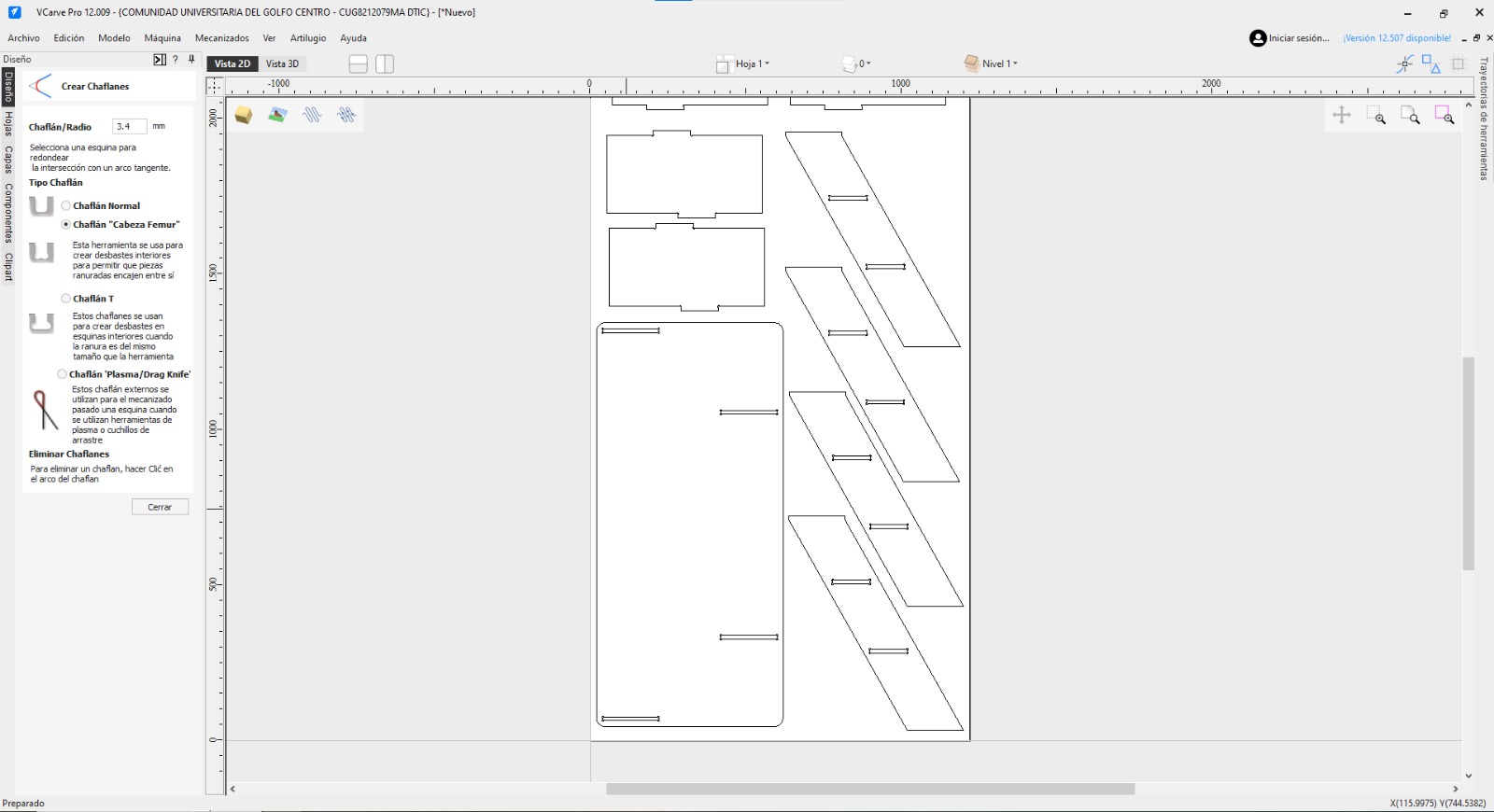
Applying dogbones to all internal corners using VCarve's fillet tool to ensure proper assembly.
Creating Holding Tabs
When cutting completely through the material, parts can become loose and get damaged by the spinning bit or ruin the final cut. To prevent this, we add "tabs". These are small bridges of material that connect the part to the main stock, holding it securely in place until the cut is finished.
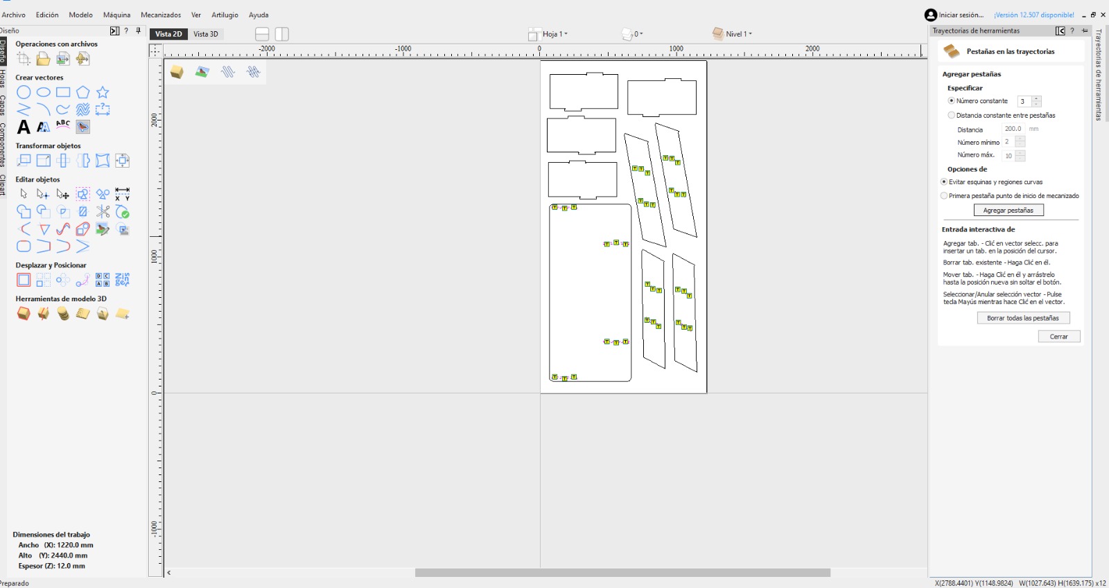
Strategically placing holding tabs along the profile cut path to secure the parts during manufacturing.
Tool Selection
Choosing the right tool is paramount. I prepared two main operations: cutting the profiles and engraving a decorative pattern.
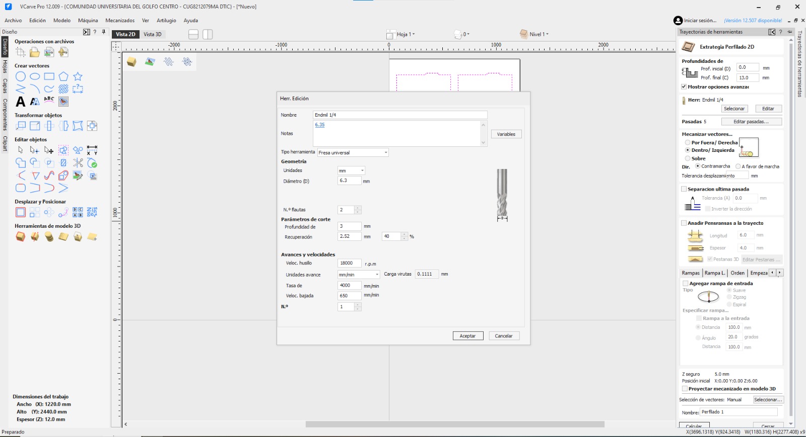
Cutting Tool: 1/4" Down-cut Endmill, it will be used for all external profiles and internal holes.
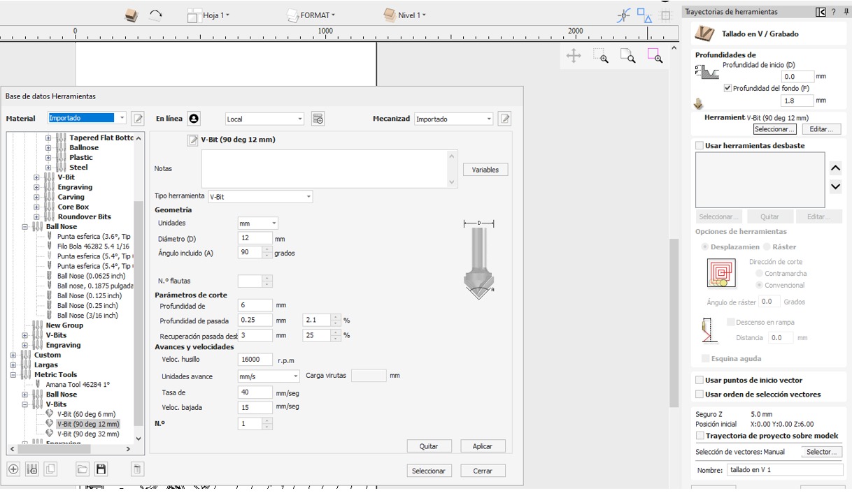
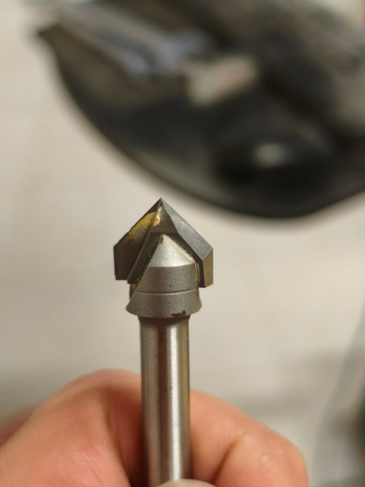
Engraving Tool: 90-degree V-Bit. Chosen for detailed line work and creating relief patterns.
Special Section: Personalized Engraving
Why we need to convert our image to grayscale?
Most CNC engraving strategies, especially photo-v-carving or 3D relief, utilize grayscale images. In a grayscale image, the software interprets brightness values as depth. Typically, pure black is interpreted as the maximum cutting depth, pure white as no cutting, and shades of gray as varying depths in between. Therefore, we must convert and contrast images to define exactly how deep the tool should go.
Preprocessing with Krita
I used Krita →, an open-source raster graphics editor, to prepare the decorative image. My main goal was to increase contrast and apply a clean grayscale conversion so the V-bit would create a legible pattern.
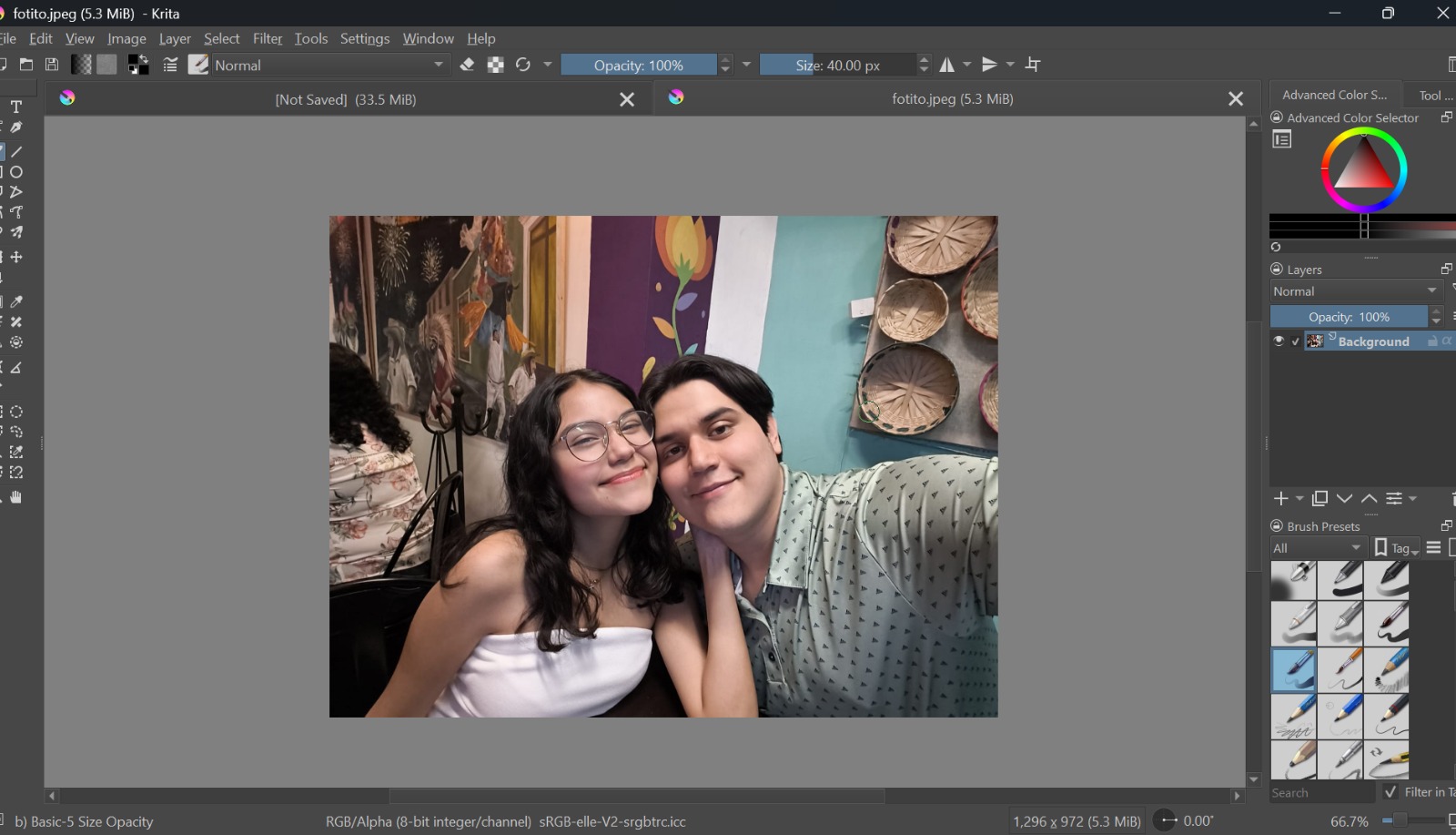
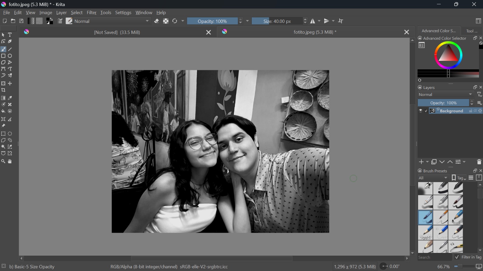
Left: Original image. Right: High-contrast, adjusted grayscale result after applying filters in Krita.
Engraving Setup in VCarve
With the prepared image, I went back to VCarve to set up the specialized toolpath.
Importing the preprocessed grayscale image into VCarve and positioning it on the desired DXF.
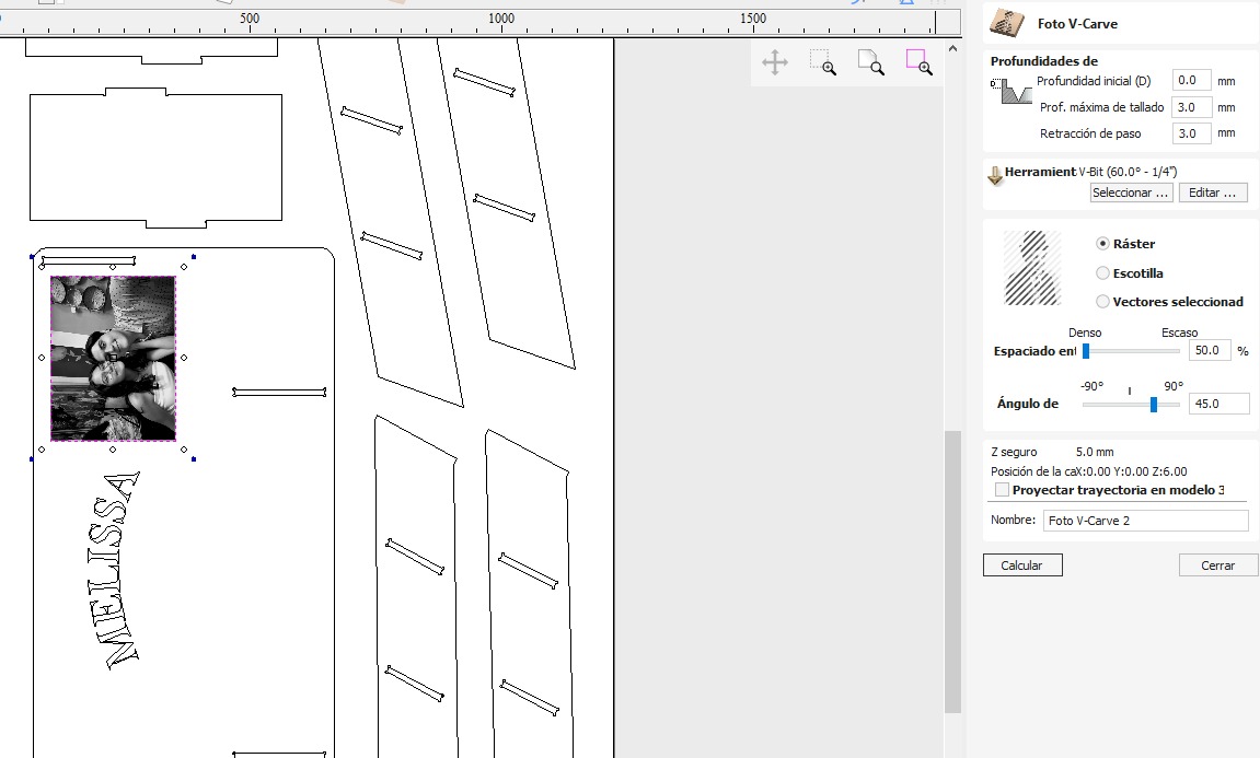
Setting up the V-Carving toolpath using the prepared image, defining maximum cutting depth based on image intensity.
VCarve 3D simulation showing the detailed relief created by the engraving toolpath.
Final Simulation Hero Shot
Before exporting the G-code to the machine, I must verify the entire job in the 3D simulator. This shot shows all profiles cut, dogbones applied, tabs visible, and the completed decorative engraving. This ensures there are no collisions or errors in the cutting sequence.
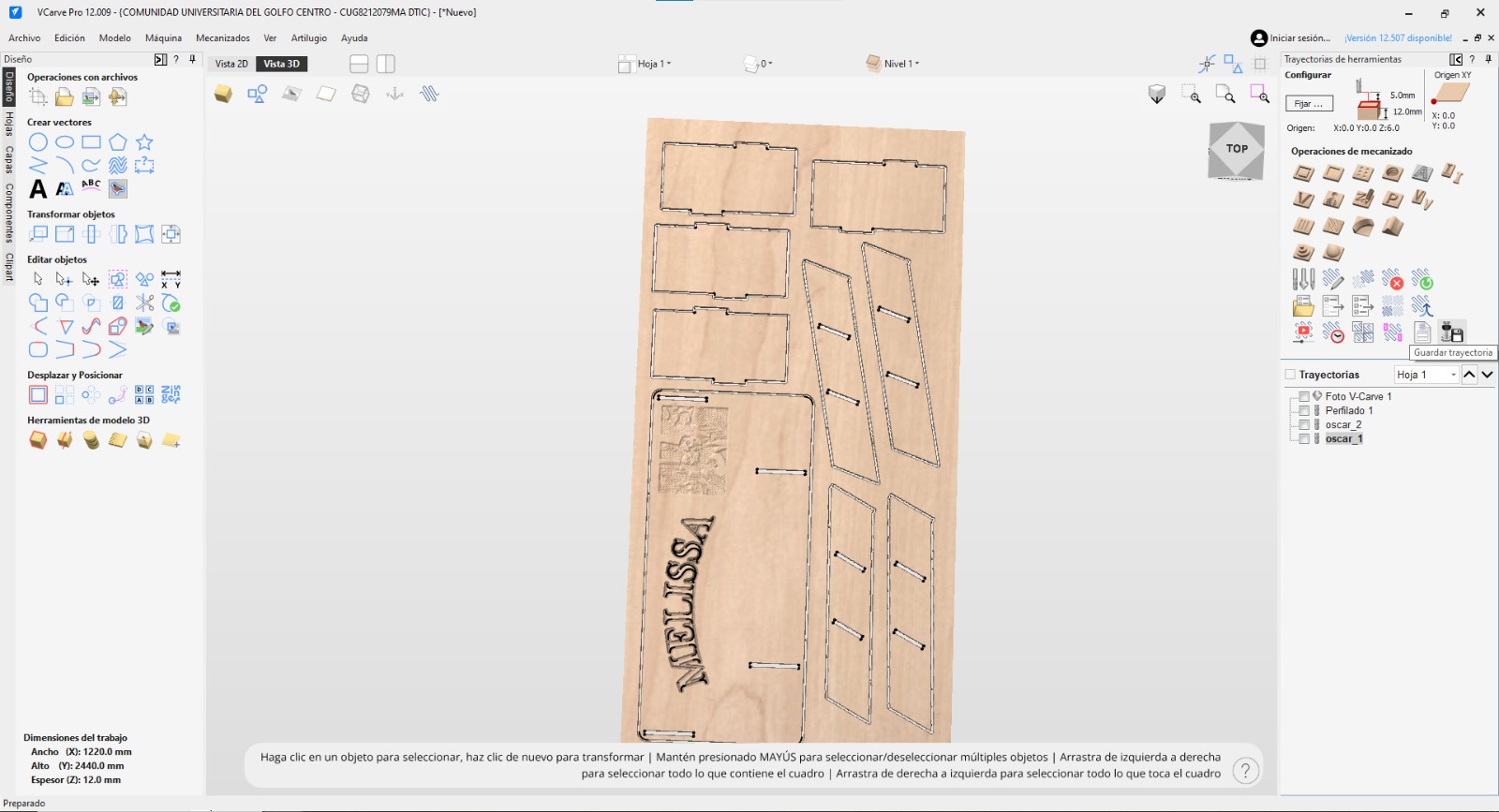
Complete 3D simulation rendering of the manufactured furniture piece, including all cuts and engravings.
Machining on the CNC Router
With the G-code generated and exported, it was time to move to the workshop and set up the large format CNC machine.
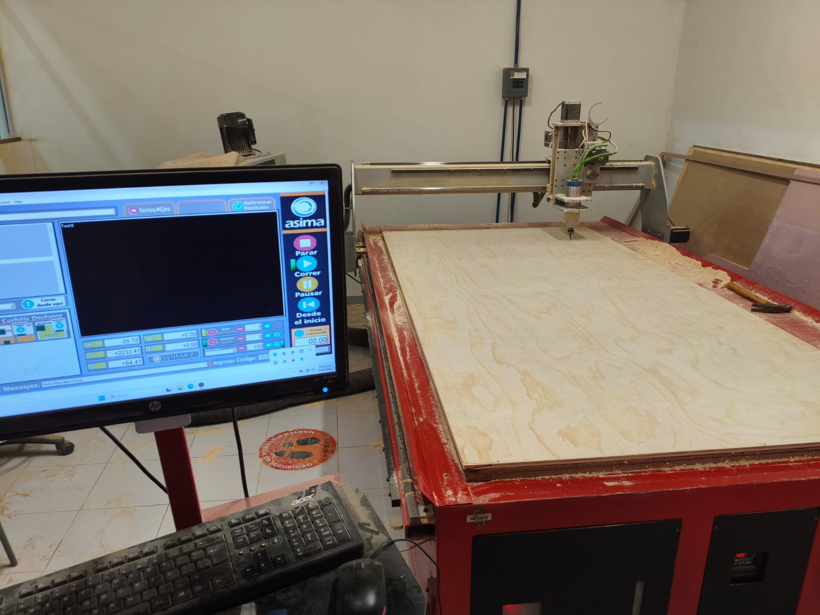
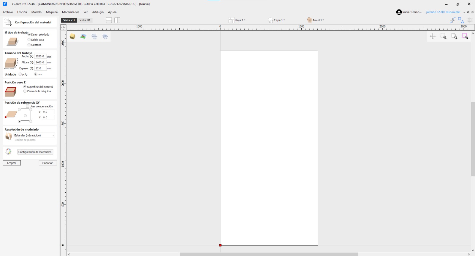
Material Setup
For this project, I used a standard wooden board measuring 2.44 x 1.22 meters, with a thickness of 12mm.
⚠️ IMPORTANT NOTE:
In this specific machine, the wooden board must be firmly nailed down to the sacrificial bed to secure it. It is absolutely crucial to take this into account when placing the nails and setting up your cuts, otherwise, the router bit could hit a nail, causing a dangerous accident and destroying the tool.
Changing the Bit & Setting Up
Since my first operation was the decorative V-Carving, I needed to change the standard bit to the engraving V-Bit.
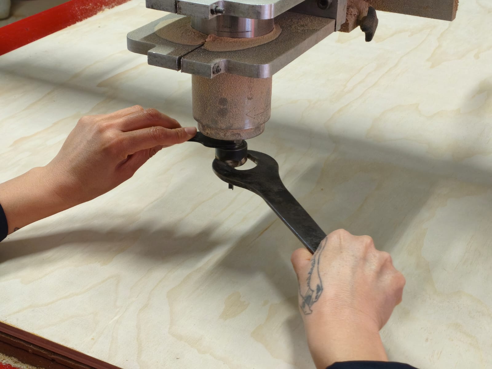
Using the wrenches to carefully loosen the collet and remove the previous endmill.
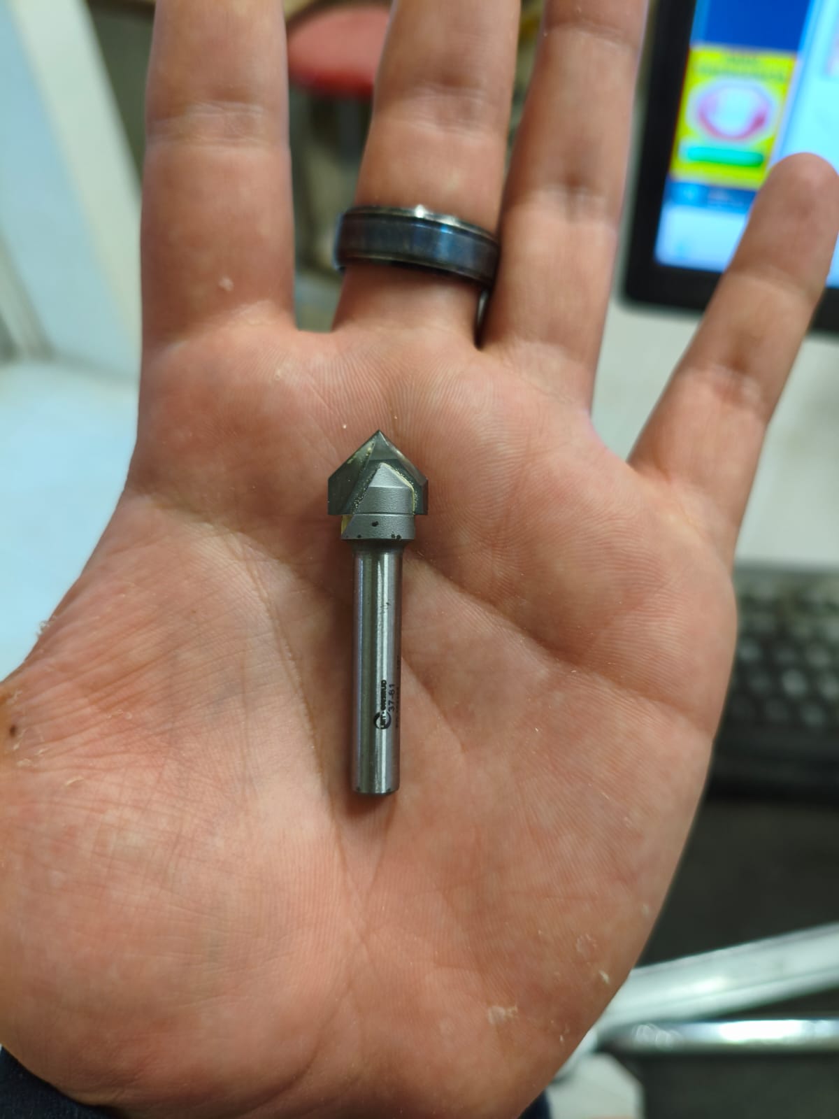
This is the specialized V-Bit I installed specifically for the engraving toolpath.
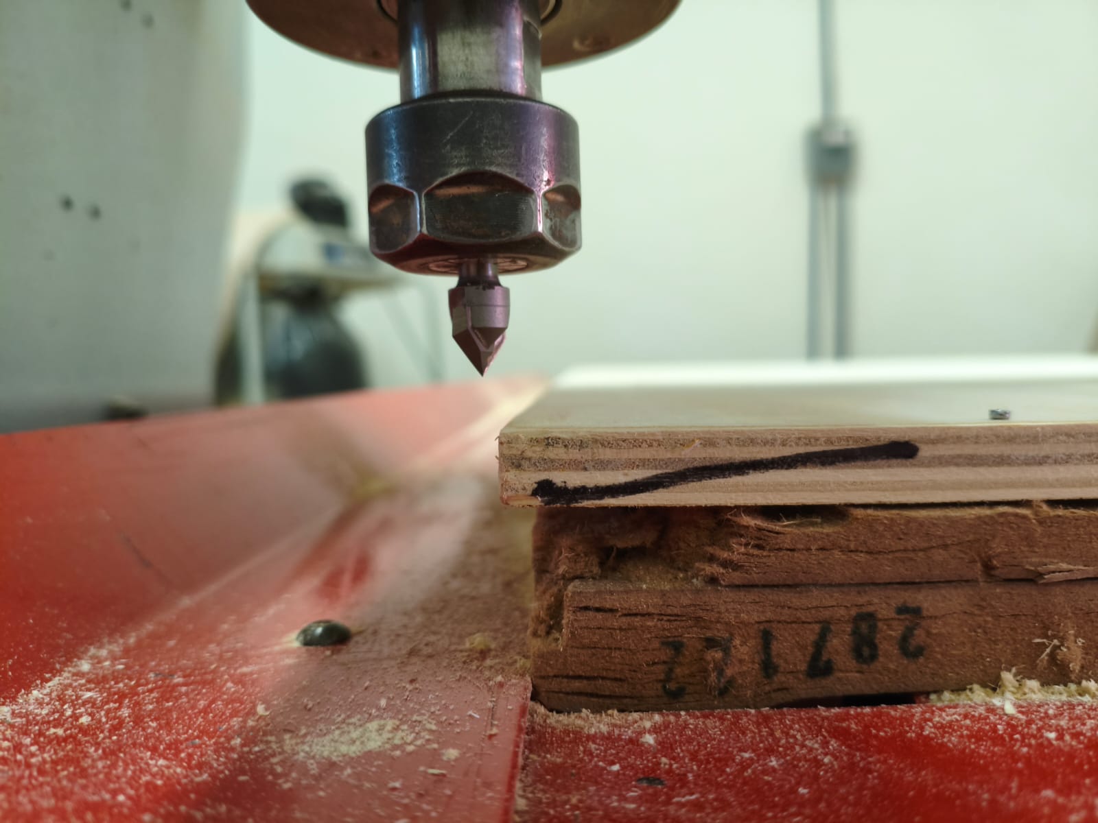
Defining the Zeroes
With the correct tool secured, I manually moved the spindle to the starting corner of my material to define the X, Y, and Z zeroes (setpoints).
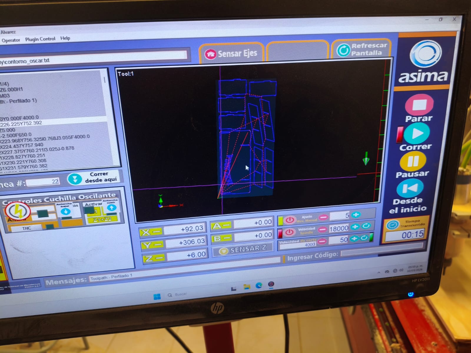
Control Interface
The control interface software is simple but highly effective. You can jog the machine in steps using the keyboard Arrow Keys for the X and Y axes, and the Page Up / Page Down keys for the Z axis. If you want the machine to jog faster, you just need to hold down the Left Shift key simultaneously.
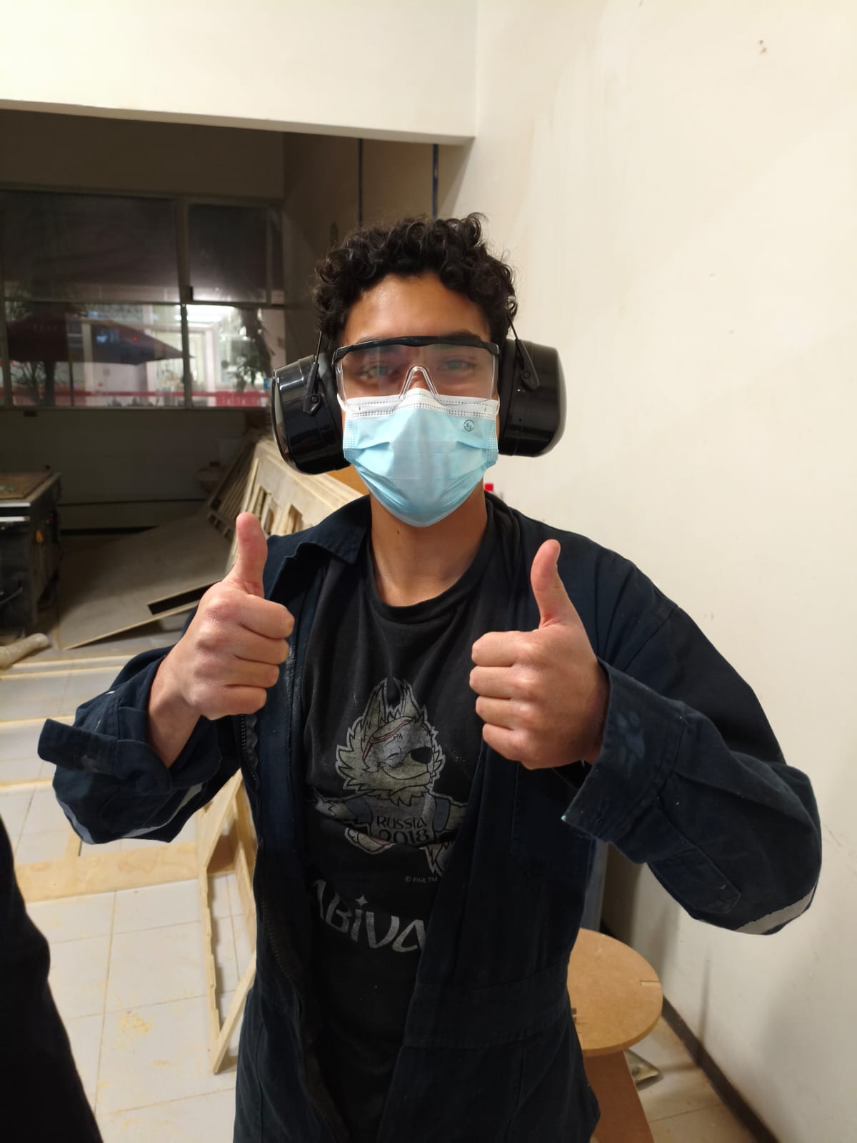
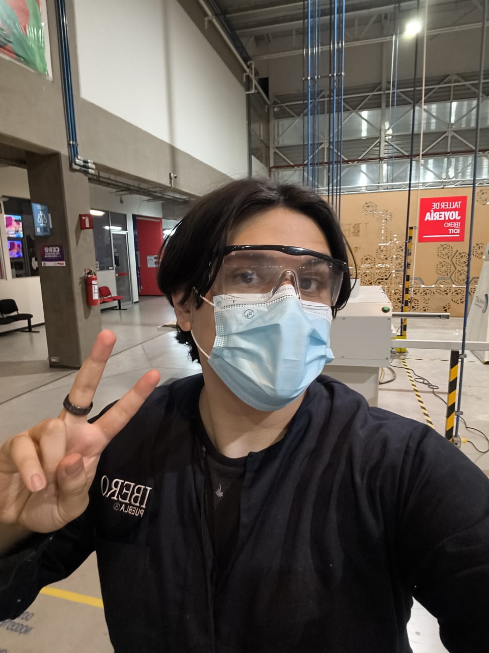
Note: Remember folks, always use your safety equipment correctly!
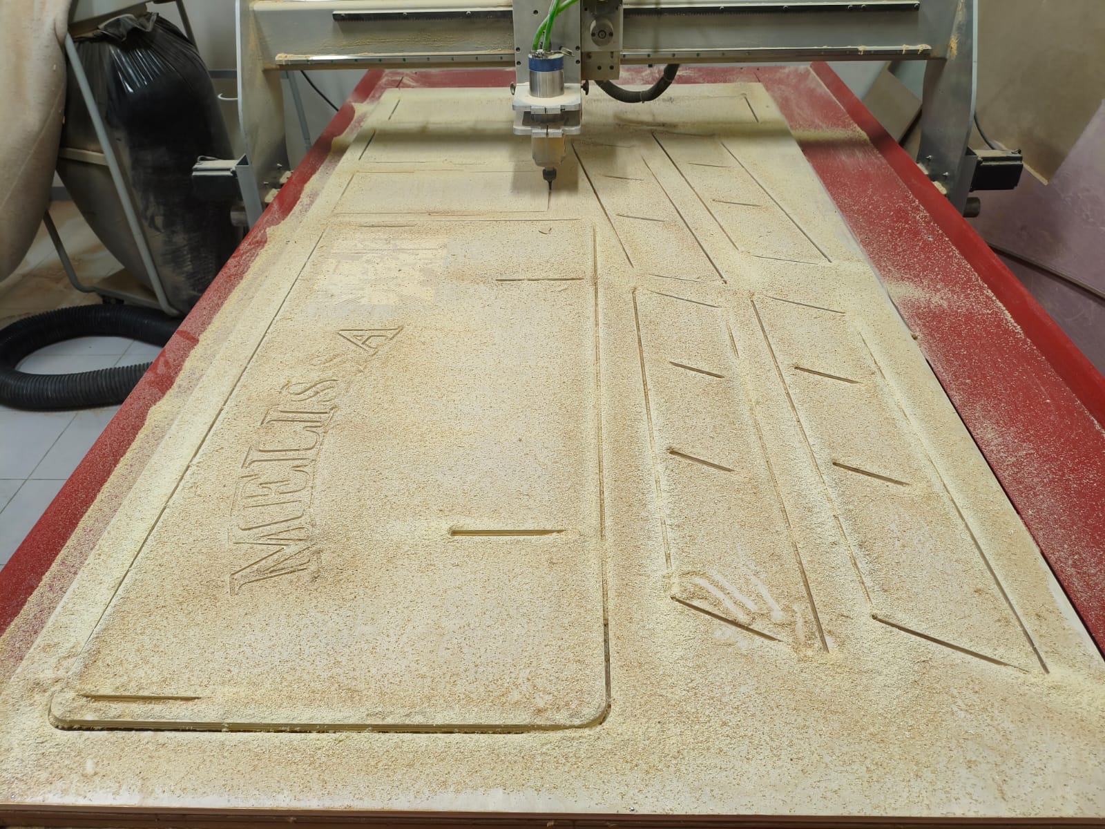
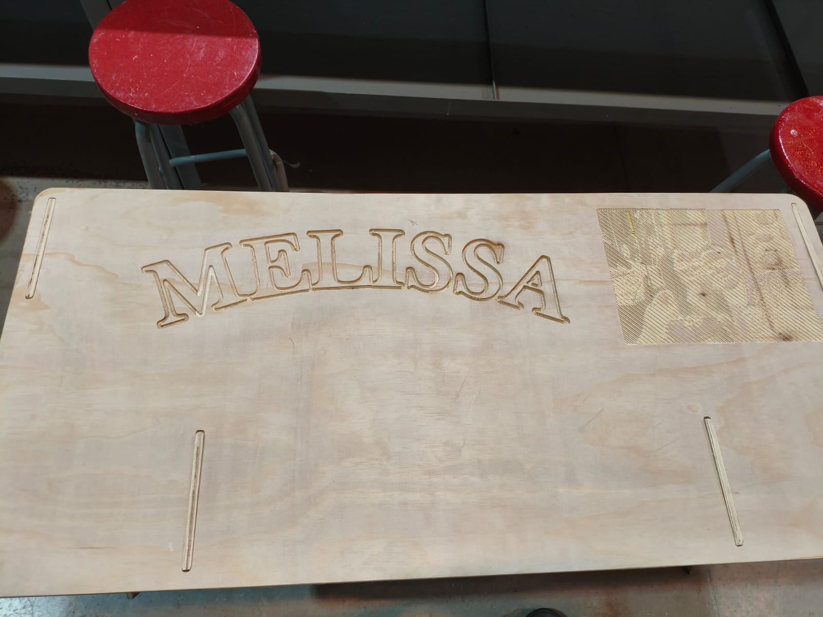
1. The Engraving Process
Once everything was secure, zeroes set, and safety gear on, I hit "Run" for the first G-code file.
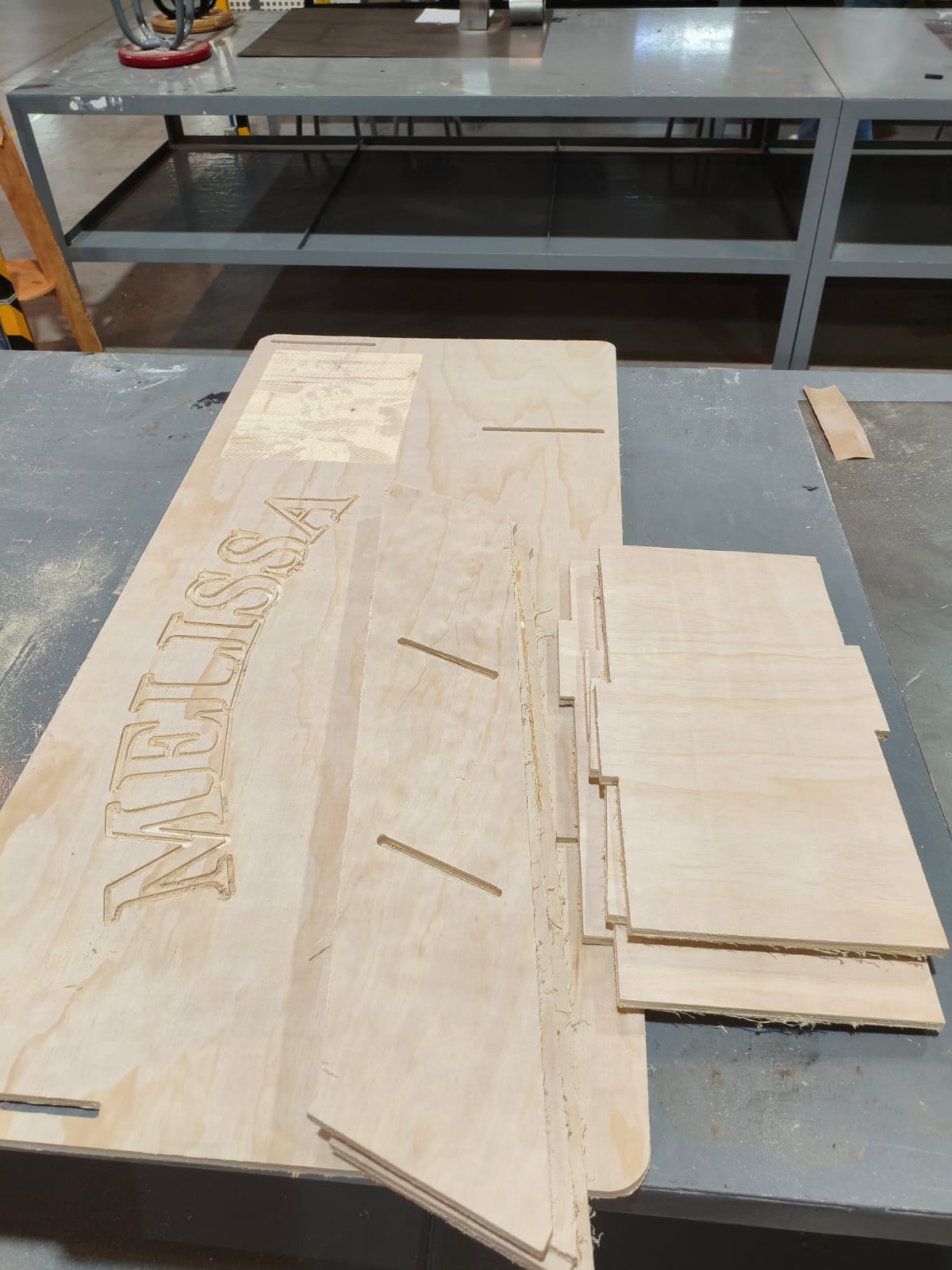
2. The Cutting Process
After the engraving was flawlessly finished, I paused to change the bit back to the 1/4" cutting endmill, re-calculated the Z-zero for the new tool length, and ran the second file for the profile cuts.
Post-Processing and Assembly
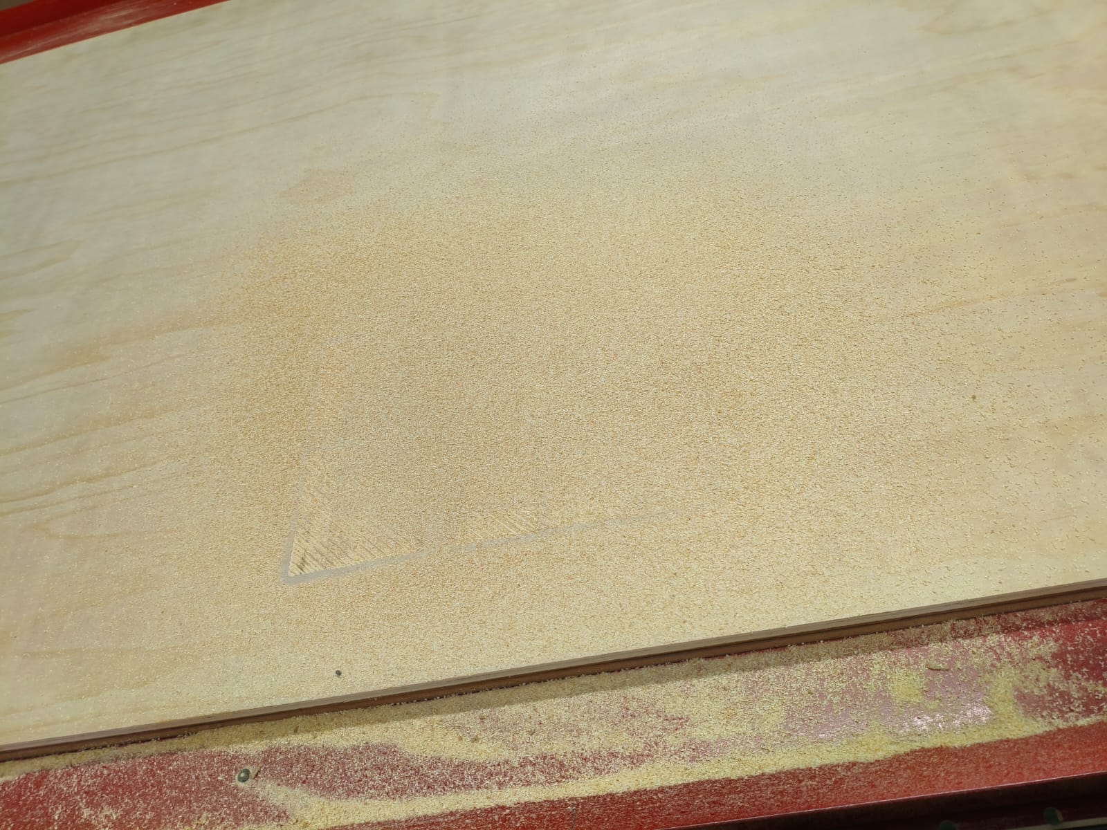
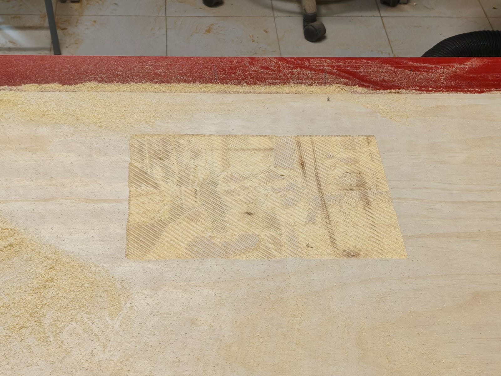
Sanding
Right out of the CNC, the machined wood pieces always have burrs, splinters, and rough edges where the tabs were cut. To ensure a perfect press-fit and a nice tactile feel, everything must be thoroughly sanded.
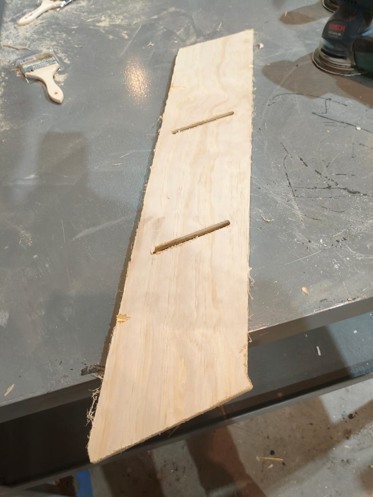
Before: Rough edges and burrs left by the milling bit.
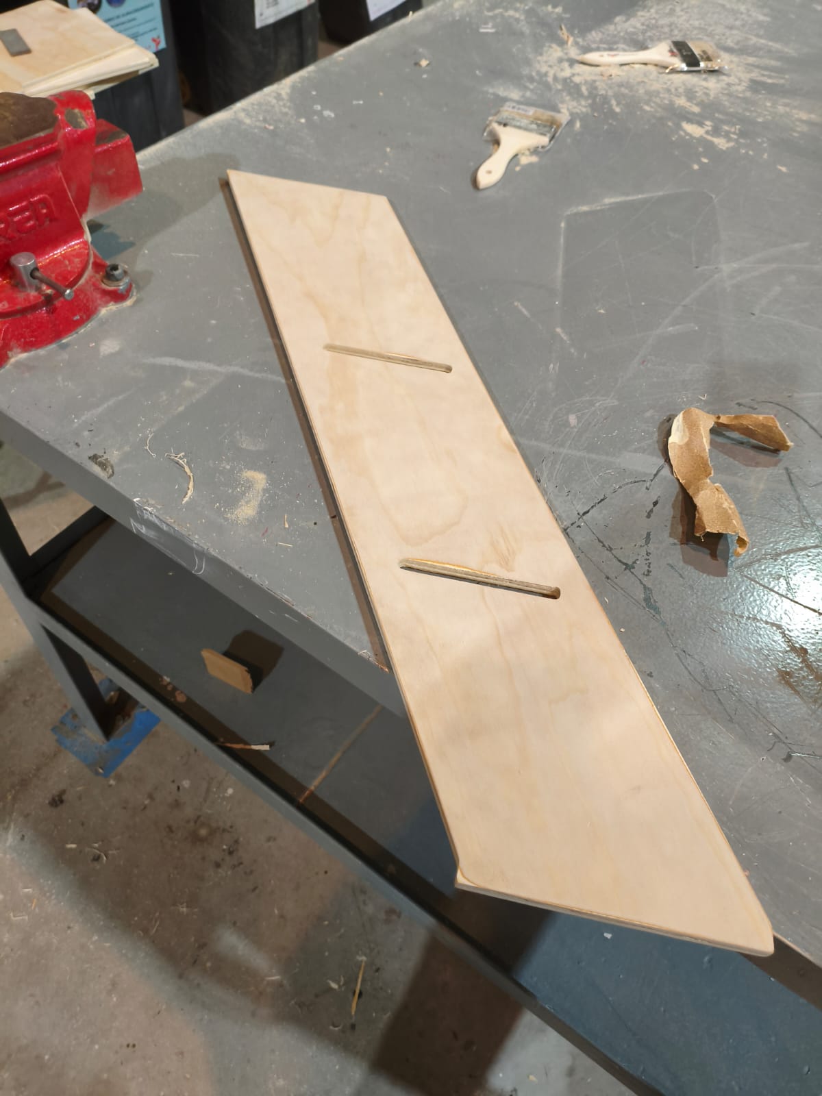
After: Smooth, clean edges ready for assembly.
Assembly Time!
This is the most satisfying part. Thanks to the precise tolerances and the dogbones we implemented earlier in VCarve, the pieces slotted together securely without needing any screws or glue.
Assembly Hero Shots
Conclusion
This week's assignment was incredibly entertaining and rewarding. Working with large-format CNC machines makes you realize how freely you can express your creativity on a much bigger, functional scale. I love being able to manufacture my own furniture from scratch—taking a concept from the digital world in SolidWorks all the way to a physical, usable, and beautiful varnished piece in the real world is an amazing feeling.
Files
Here you can download the original DXF vector files I generated for this furniture project: