
Week 03
Computer Controlled Cutting
// MAIN OBJECTIVE \\
In the third week of this course we learned how to create 2D sketches in Solidworks and convert them to dxf format. With this vectorized sketches we learned how to use the laser cut machine for cutting MDF with that personalized shape. With that knowledge we need to make an assembly, using MDF and various laser-cut joining parts.
2D Design
Before we start, if you want to see the essential protocols, Kerf calibration, types of joints and various tests of this week, you can check the group homework, it's HERE →.
After the safety traingin I've learned a lot of things, starting of how to turn on the machine, precautions while using the laser like avoiding to stare with your bare eyes at the laser and turn it off untill the cut is about to sart; I also learned the fire extinguisher location in case of emergency (more details in the group homework).
Working Materials
The two types of 2D crafting machines (laser and vinyl cutter) can handle a large amount of materials, the laser can handle wood for engraving, MDF, acrylic, cardboard, paper and some plastics for cutting, and the vinyl machine can cut through paper, tape, vinyl and some sticky materials such as cooper sheets with stickers for making wearable circuits.
Sketch Parameters for MDF cutting (Laser)
First we need to know the specs of the materials we are going to handle, the MDF (Medium Density Fibreboard) is a composite material made of wood fibers and synthetic resin, it is commonly used to make furniture, doors and daily objects. The MDF that we will be using has a 3mm thickness and a maximum of 1.5 X 1 meters width and height, so all the parameters need to be adjusted to perform cutting and engraving.
SOLIDWORKS Sketch Design
Once we'd set all the parameters, we can start designing the pieces of the MDF assembly.
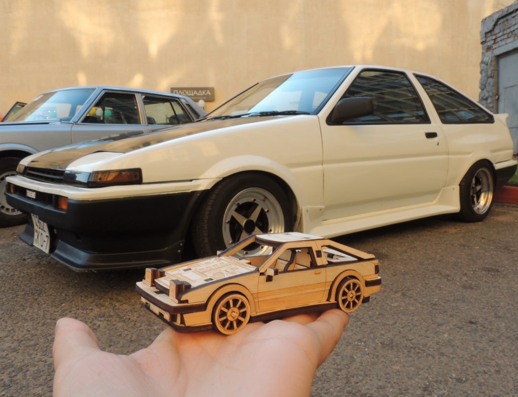
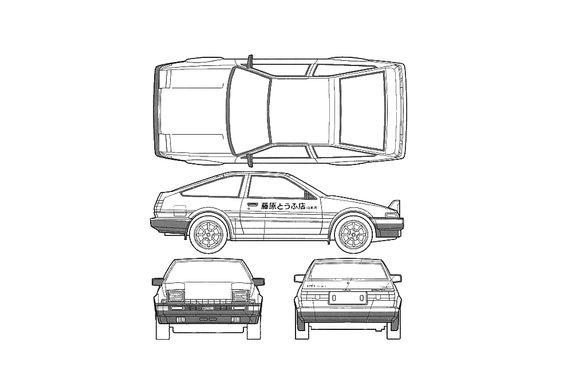
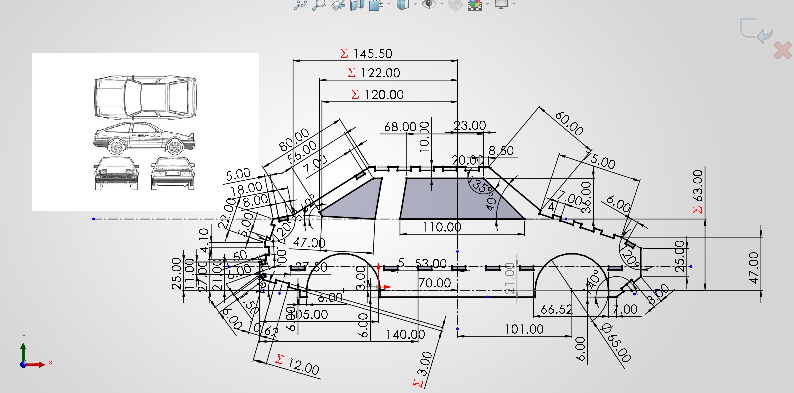
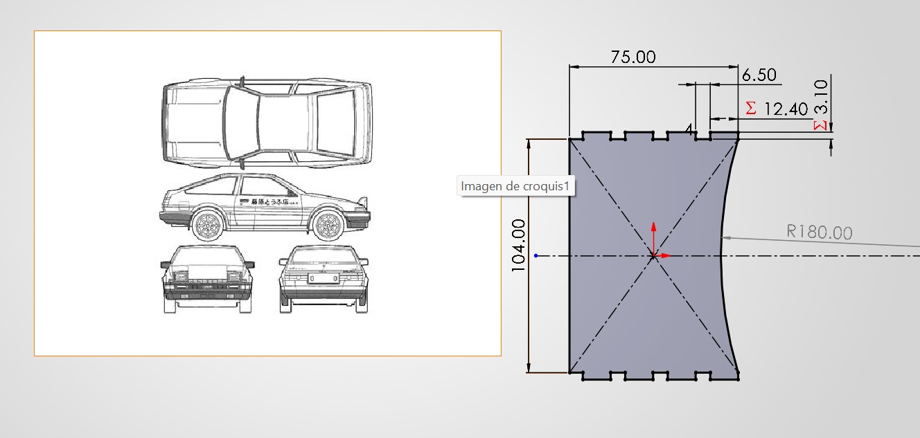
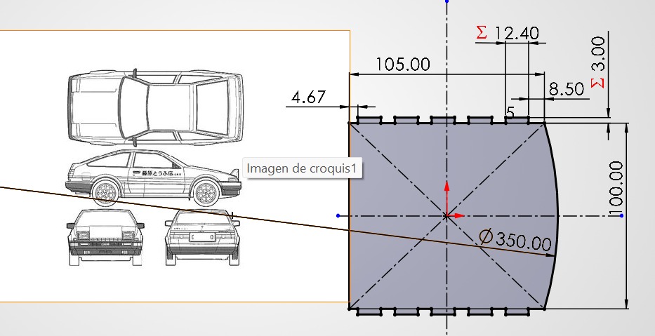
For my assembly part, I designed from scratch the famous car from the anime Initial D, the Toyota AE86 (ハチロク). I downloaded an online picture of the car in MDF for reference and started my 2D design.
Designing The Proyect
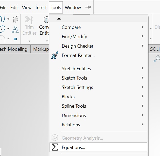
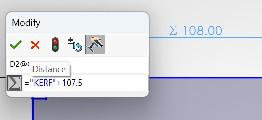
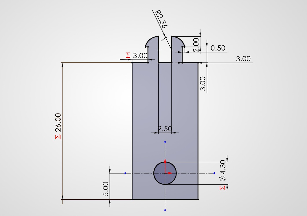
Before we start, here is a little guide to parametrize measurements with the Kerf in SOLIDWORKS:
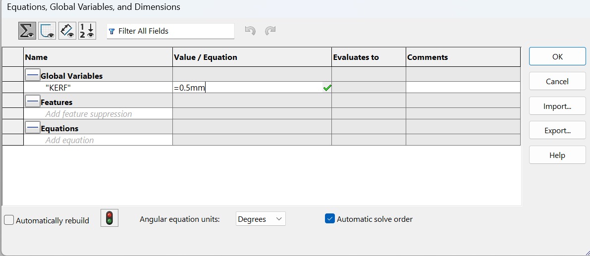
This proyect is an assembly fully made of MDF, it contains multiple parts adapted to the Kerf calibration, using different types of joints to make a car that can move forward and backward using only MDF laser-cutting.
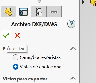
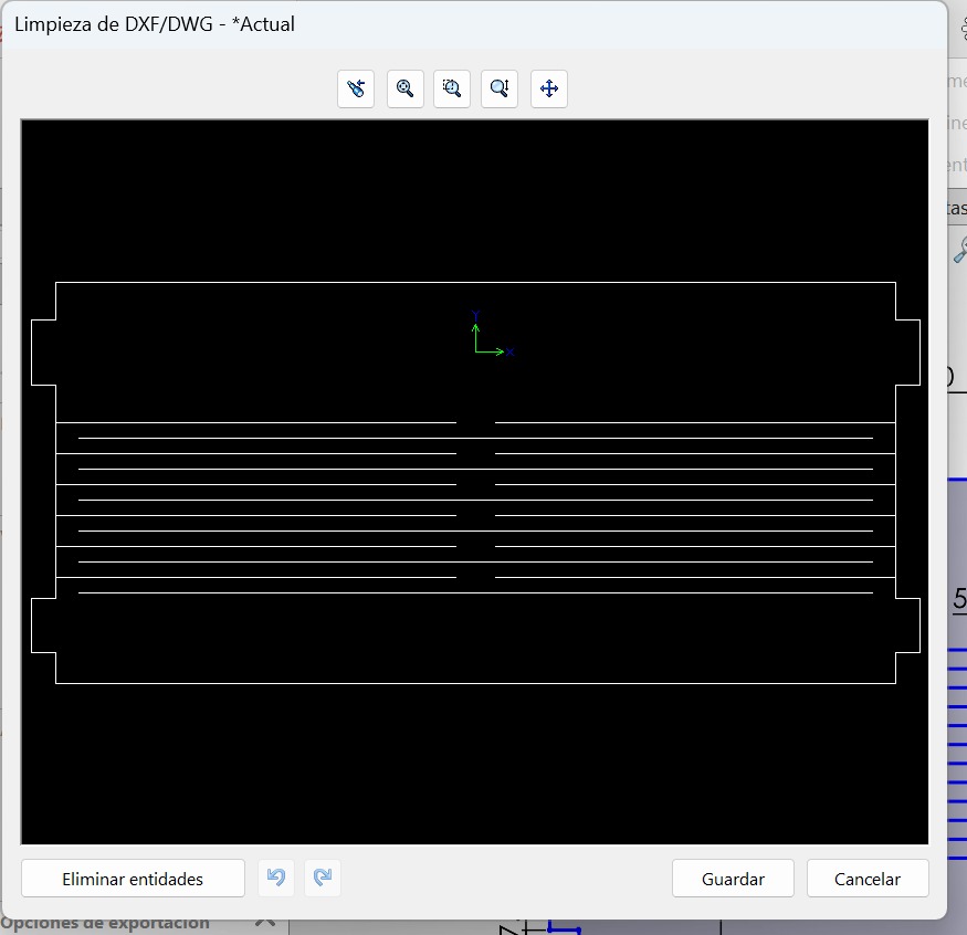
First of all, we need to convert a 2D designed part in SOLIDWORKS to DXF format, and for this I did the following:

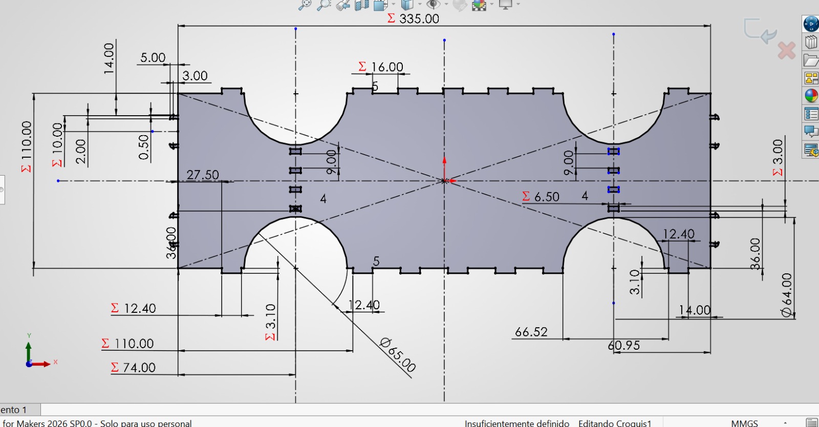
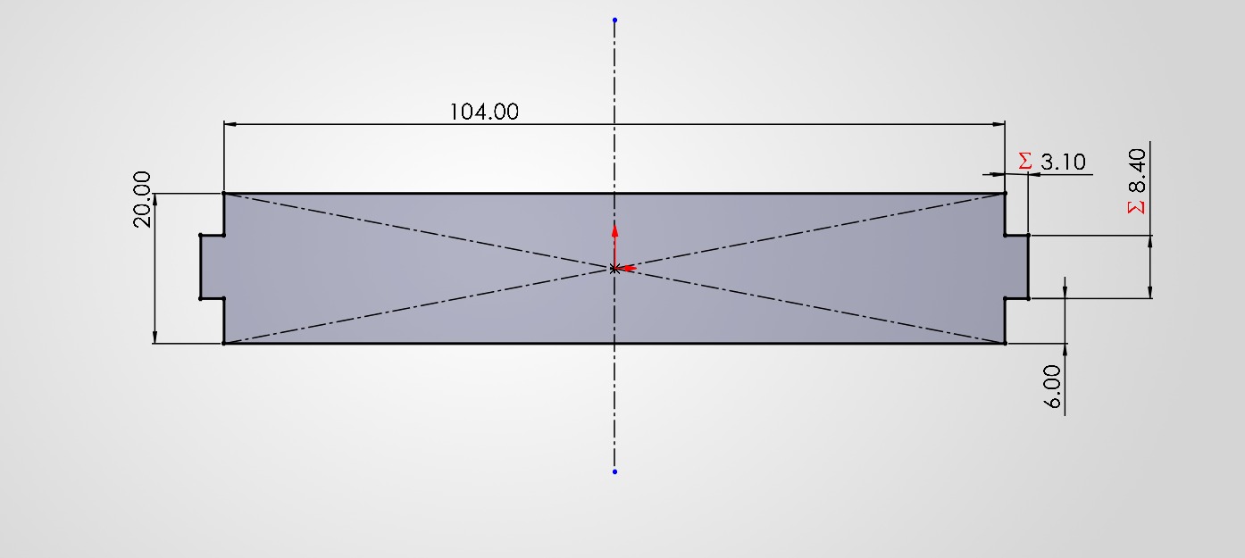
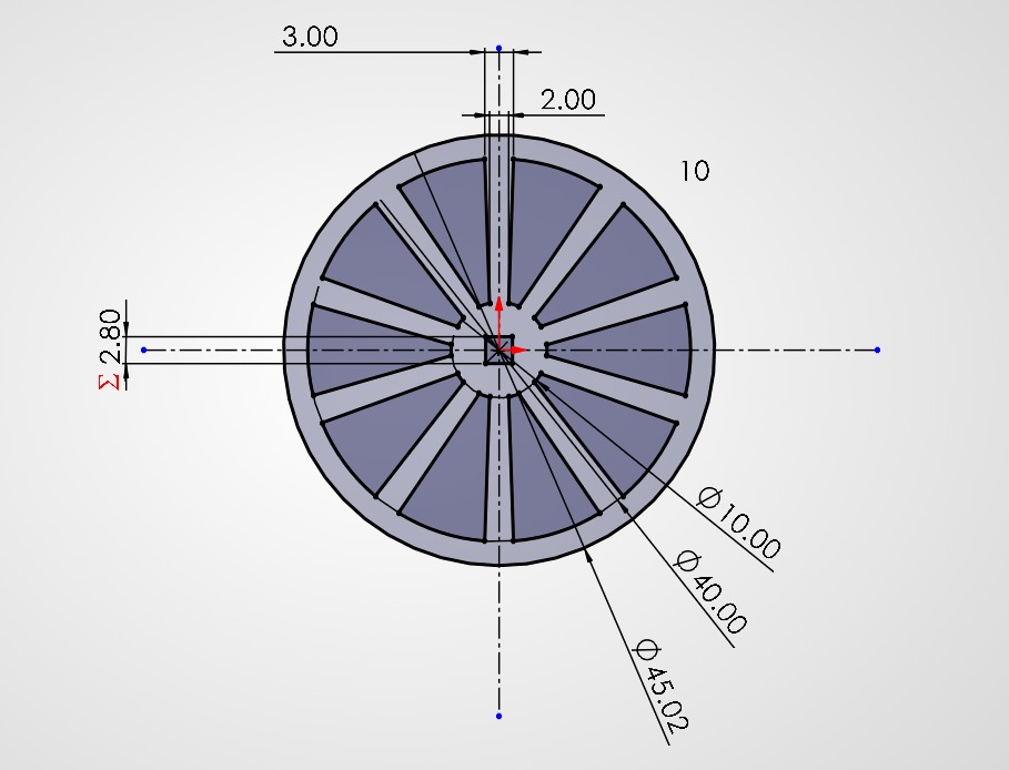
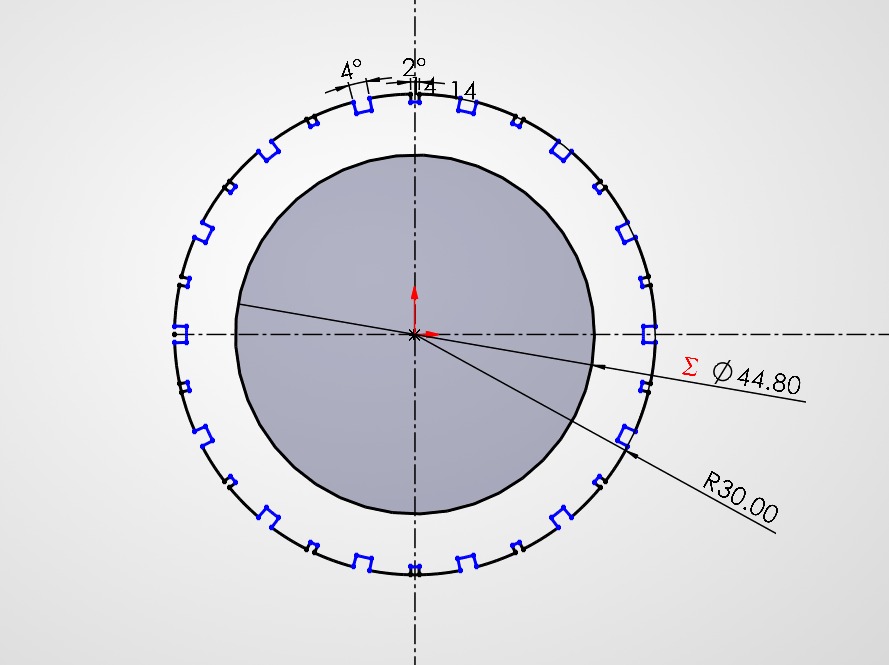
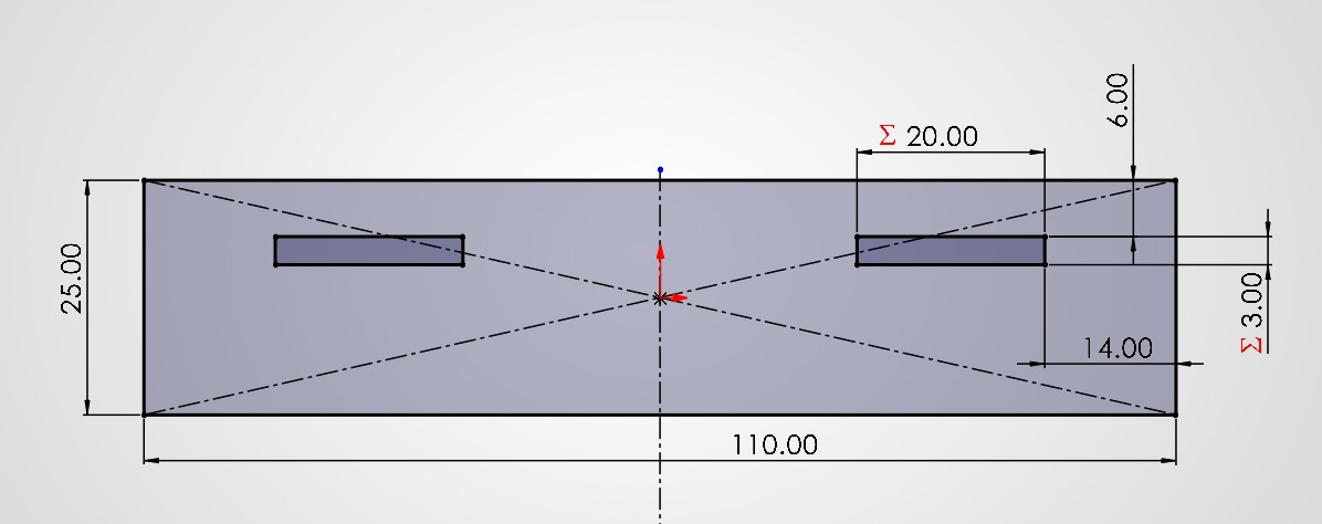
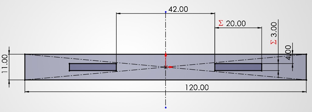
Once I knew how to create a DXF file, now I designed all the assembly parts (all important measurements are parametrized with the Kerf obtained in the group assignment):
Once I designed everything that I needed, a 3D assembly was made to check the final preview of the proyect:
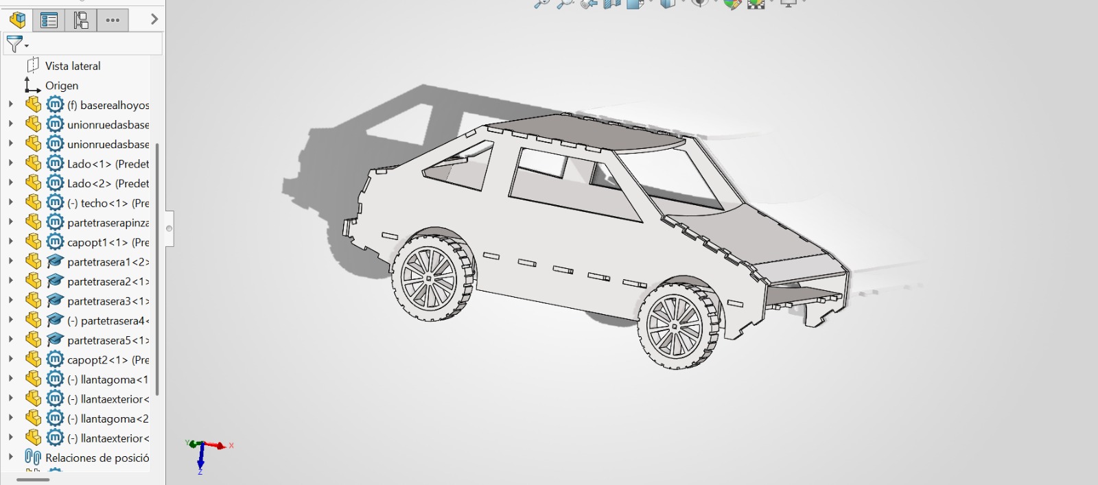
My 3D SOLIDWORKS assembly part.
Now the fun part... start laser-cutting.
Before we start to cut the parts, we need to know some safety rules for using the machine:
- Protoboard
- LEDS
- PILA
I need to mention that I created letters in DXF format for the engraving using Autodesk from AutoCAD.
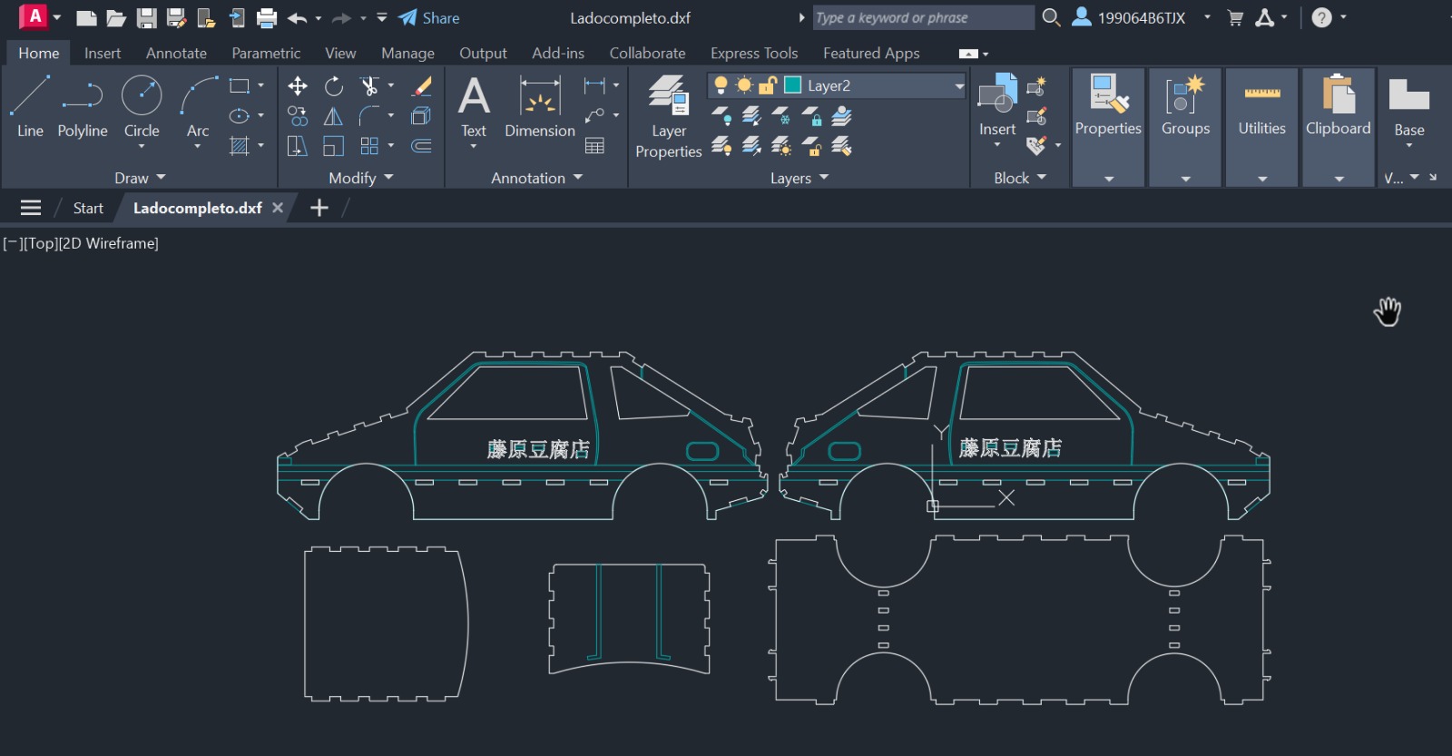
Letters and details made in Autodesk.
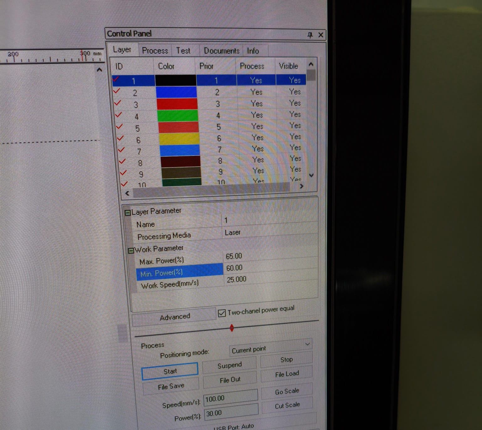
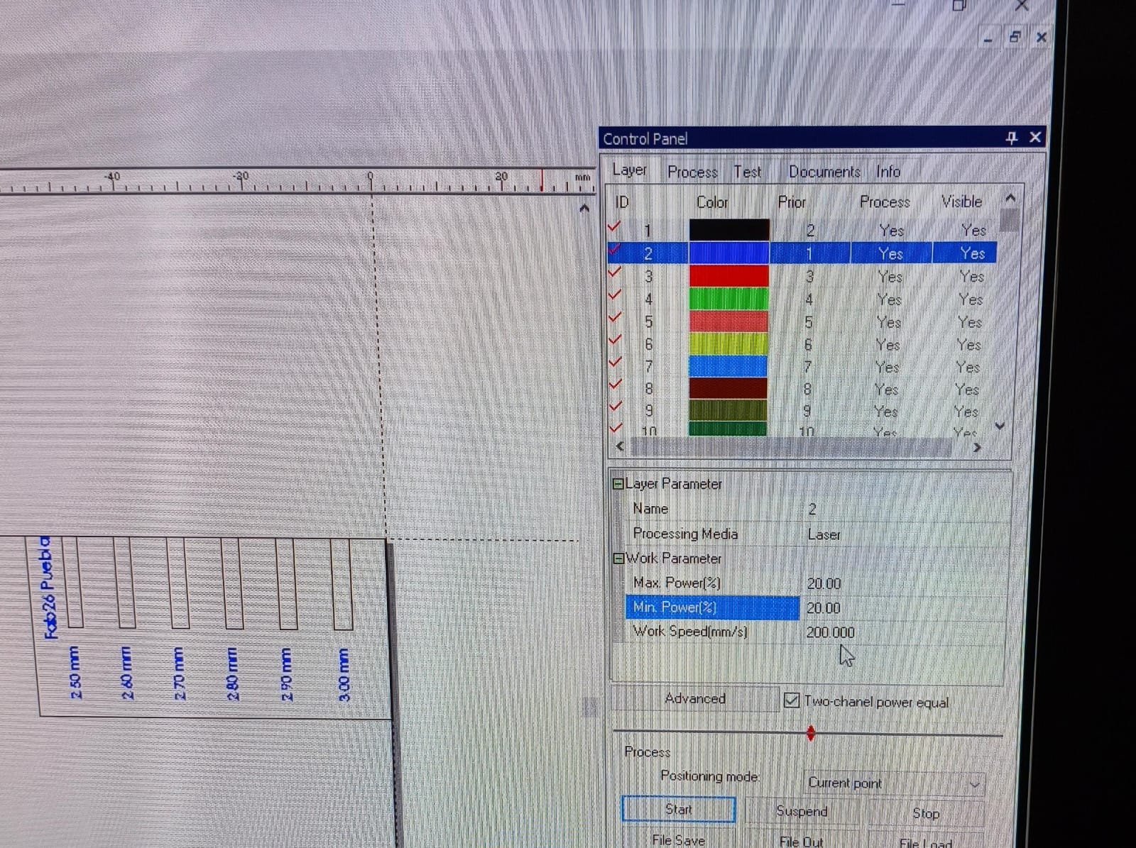
Now, with all the files ready, I imported them to SmartCarve, the laser-cutting software and with the fill function I made more engraving details.
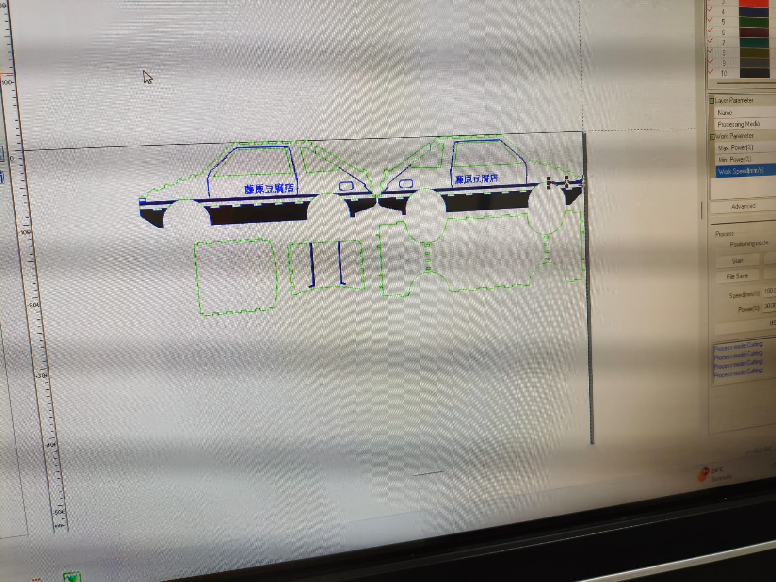
SmartcCarve parts imported.
Since I was connected via USB cable, the only thing I needed to do was adjusting the parameters and press "Go Scale" for measuring the size of the cut on the machine and "Start" for doing the cutting and engraving.
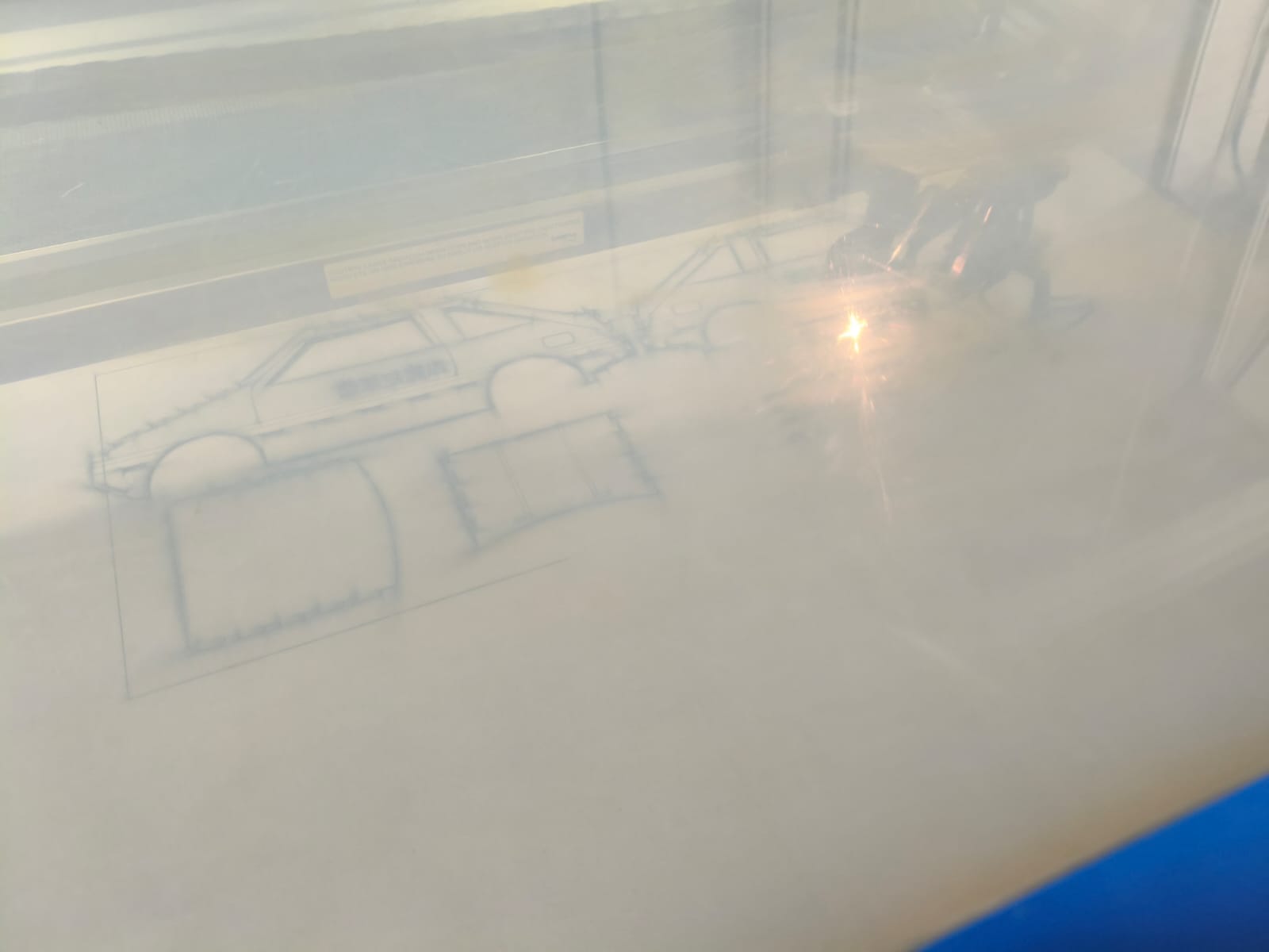
Cutting and engraving the parts.
Real time cutting process.
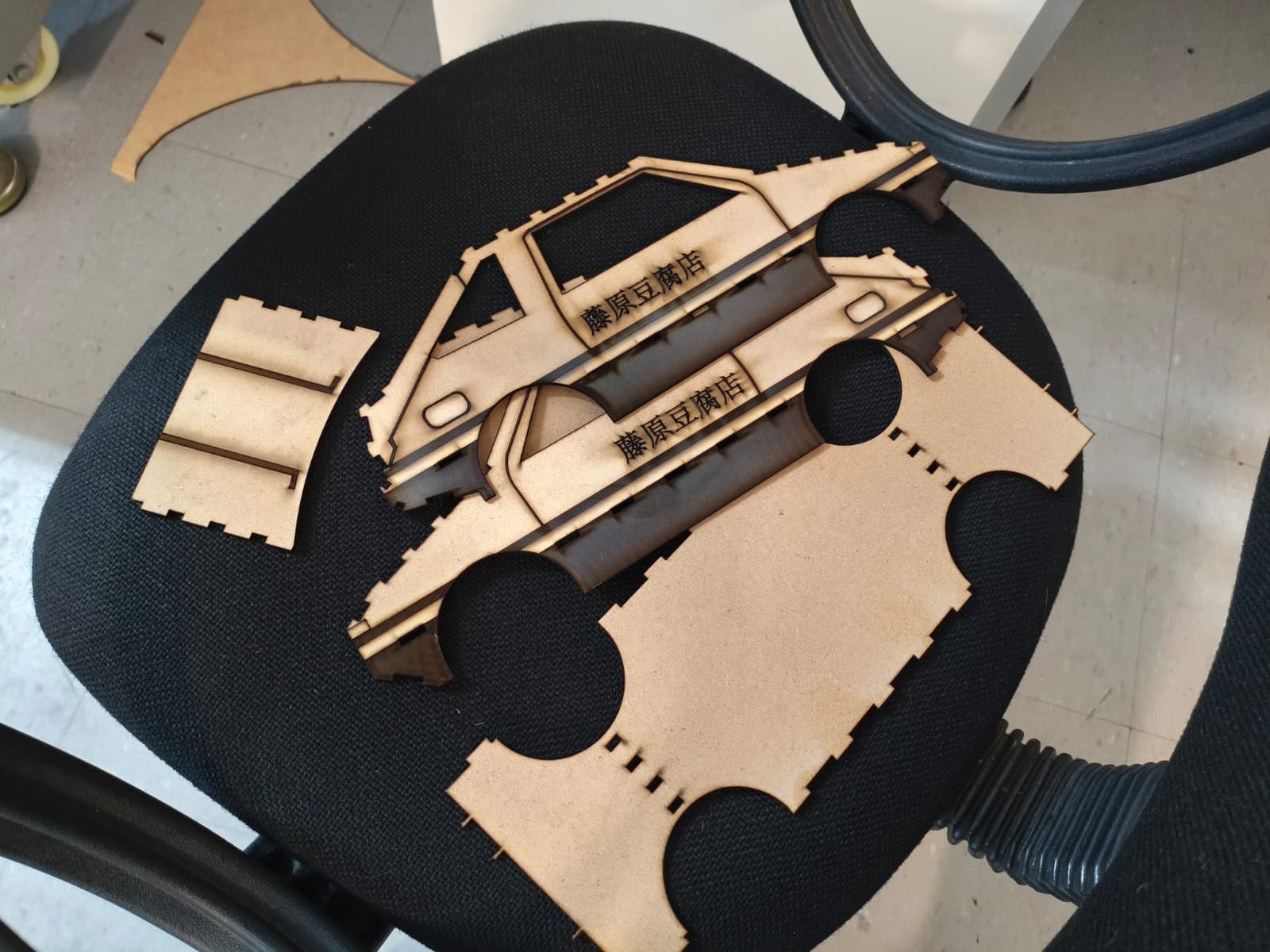
Cutting and engraving result.
After obtaining all the parts, I made the assembly, you can see my timelapse down here:
Time lapse of the assembly.
Final Results
Here are all the results and some hero shots of the AE86 MDF car!
Trunk testing.
Movement testing.
Vinyl Cutting
As seen in previous weeks, we learned how to vectorize images to create SVG files. This step is crucial for computer-controlled cutting because machines rely on these mathematical vector paths to execute precise and scalable cuts for vinyl cutting and circuit making for example.
For this assignment, I generated an SVG file featuring the shape of a chess pawn. Here is the digital vector ready to be processed:
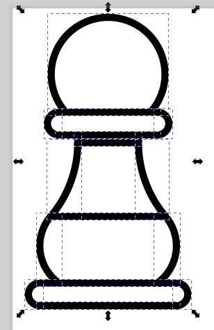
Chess pawn vectorized in SVG format.
Once the SVG file is completed, it is sent to the vinyl cutting machine. The most important steps here are adjusting the machine's parameters, specifically the size of the cut and according to the type of vinyl we are using the pressure to get a clean cut without piercing the backing sheet and removing correctly the material:
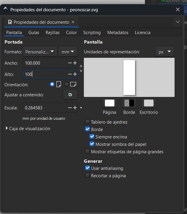
Adjusting the size parameters.
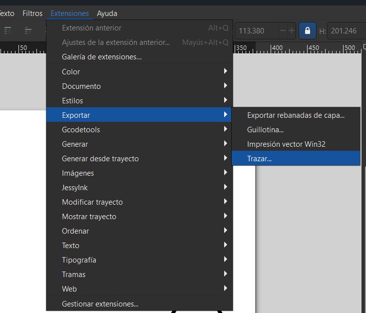
Select the tracing tool.
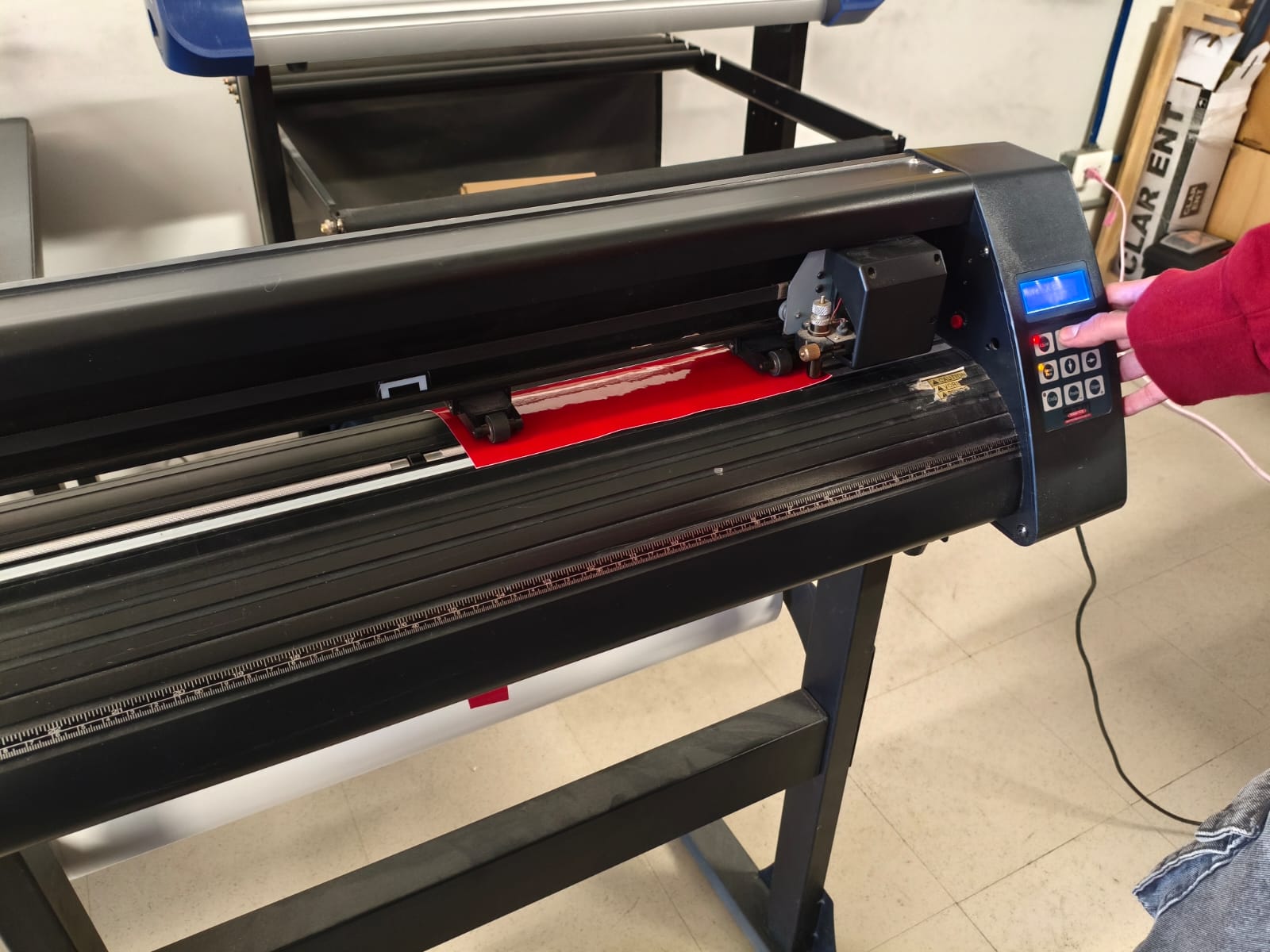
Loading the vinyl in the machine.
Sending the data to the machine and cutting.
After the machine does its job, we proceed to weed the design (removing the excess vinyl).
In this part i failed :( because I put I put the vinyl on the machine incorrectly, it was suposed to cut in the vinyl part but instead it cut the plastic. but i learned a lot and did it correctly the second time :) .
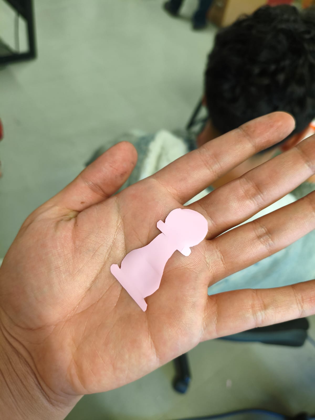
Epic fail!.
Weeding the design.
After weeding the design, I had to stick the vinyl onto something depending on the type of vinyl, in my case, it was textile vinyl so I needed to iron it with a special machine.
First of all, we need to set the temperature, for clothes and textiles is recommended 110 degrees Celsius.
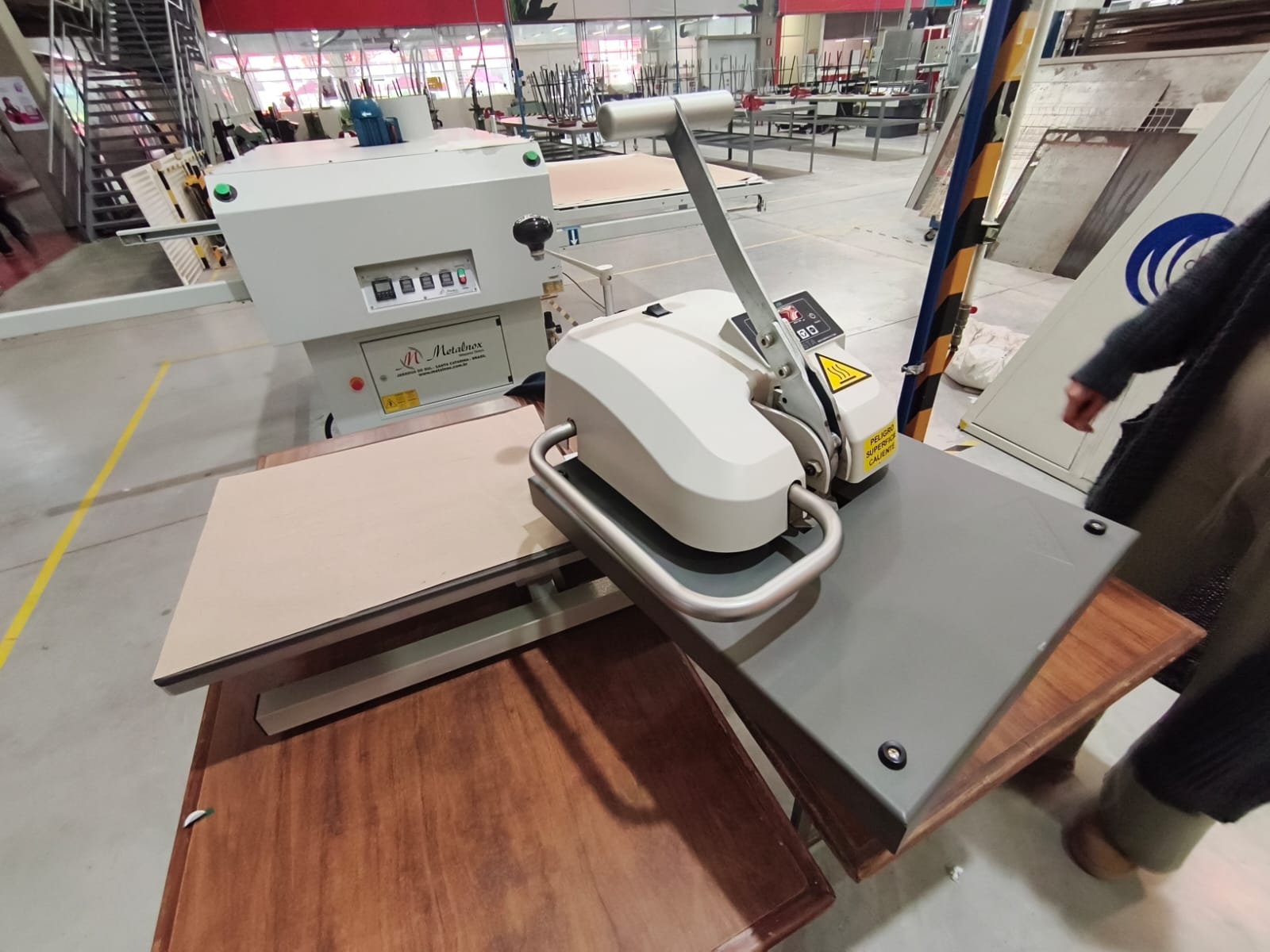
Knowing the machine.
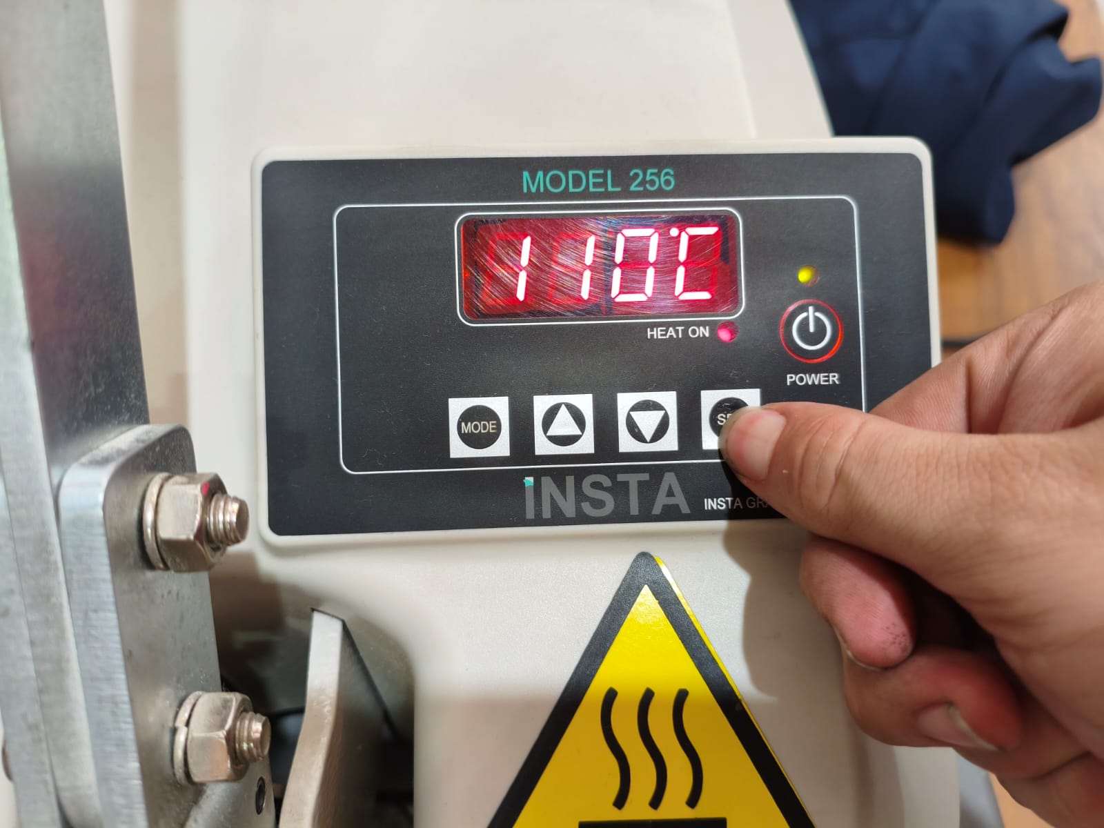
Setting temperature.
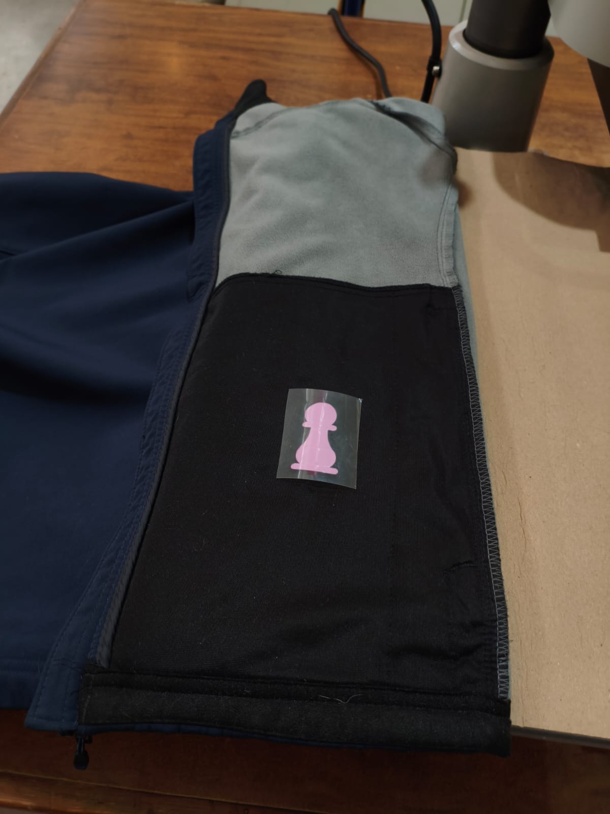
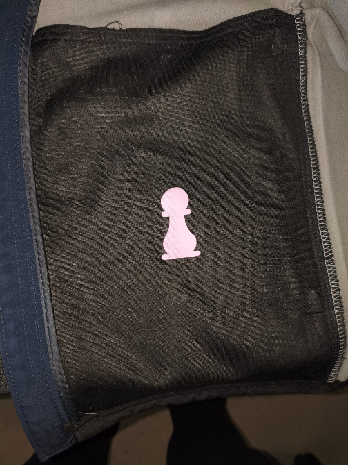
Placing vinyl.
Ironing the vinyl onto the jacket.
Conclusion
This week was perfect for learning how to manage tolerances, and I loved the creativity for making an assembly step by step. Furthermore, learning the workflow of the vinyl cutter allowed me to understand the process of 2D vector fabrication and how to transfer digital designs into physical decals. I am satisfied with the design, cut and assembly of these projects and I'm ready for the next week :> .
Files
Here you can download the original files I used for this week's assignments: