MISSION BRIEFING
This week is all about subtractive manufacturing. The goal is to characterize the machines (Group Work) and then use them to create a Press-Fit Construction Kit (Laser) and a custom sticker/circuit (Vinyl).
The Art of Destruction: Lasers & Blades
This week is all about subtractive manufacturing. The goal is to characterize the machines (Group Work) and then use them to create a Press-Fit Construction Kit (Laser) and a custom sticker/circuit (Vinyl).
Before cutting anything serious, the team gathered to test the machine's limits. We characterized the Power, Speed, and most importantly, the Kerf.
The Problem: My first attempt failed. The cut was thick and blurry, and it didn't go all the way through the MDF. I realized I had ignored the focal length.
The Fix (Calibration): The nozzle MUST be exactly 5mm away from the material surface.
I used the metal spacer tool (calibrated gauge) to adjust the bed height manually. I moved the laser up until there was a space of exactly 5mm between the nozzle tip and the material surface. This 5mm gap is the "sweet spot" where the laser beam is most concentrated and powerful.
For this mission, I decided to customize my laptop. I designed a decal using Inkscape and prepared the file for the vynil cutter machine.

Fig 1. Vector Setup
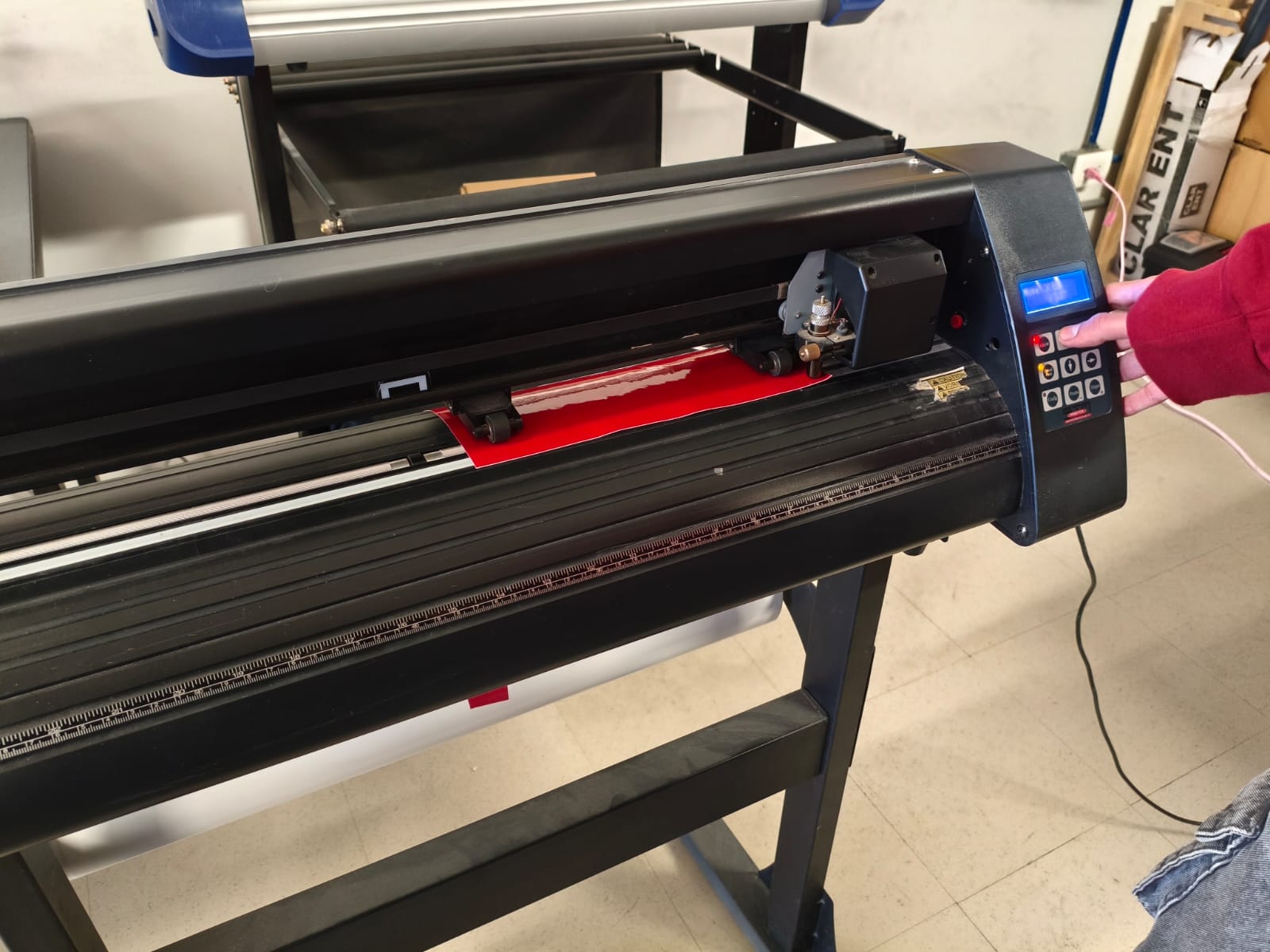
Fig 2. Loading the Vinyl
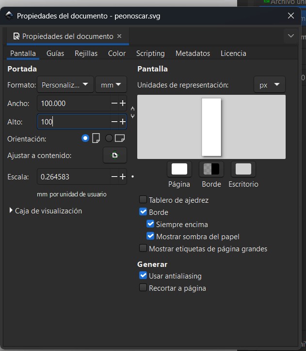
Fig 3. Weeding Detail
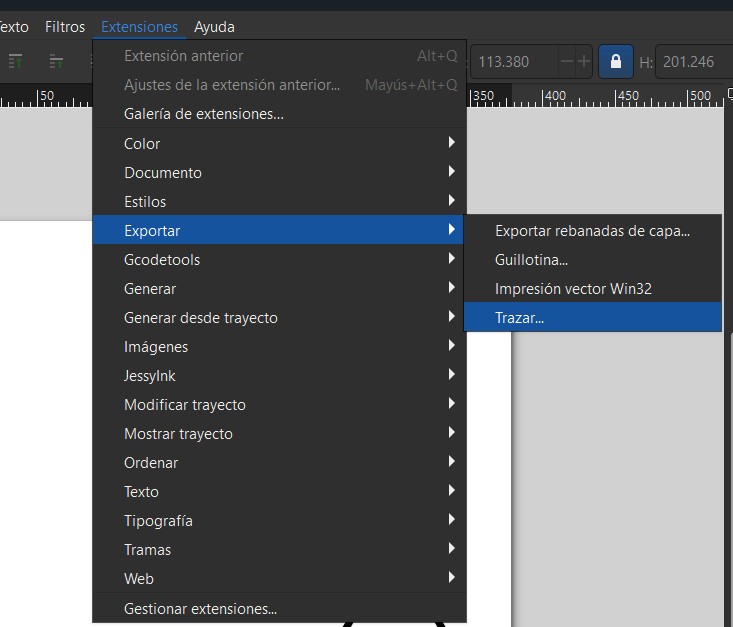
Fig 4. Transfer Tape Ready
Video 1. The cutting process
Video 2. Weeding, Transfer & Application
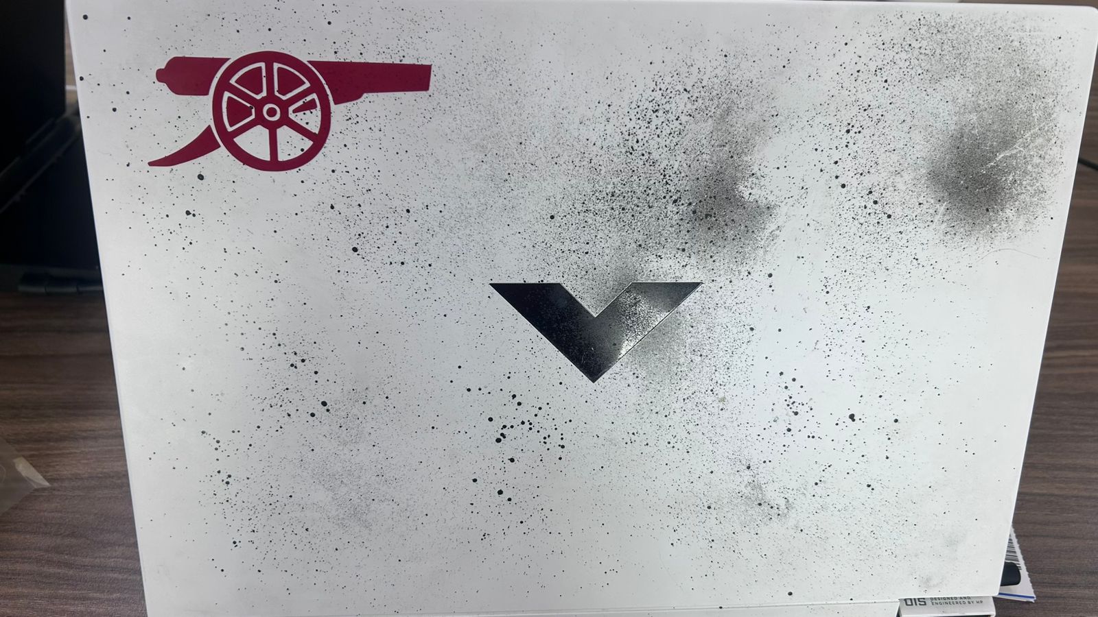
Fig 5. The final result on the laptop lid
The mission: Design a parametric piece that can be assembled in multiple ways. I chose to build a modular structure inspired by the X-Wing.
Before designing the full ship, I had to find the "Magic Number". I created a test comb to measure the laser's kerf.
Designing the test piece.
Measuring the perfect fit (Result: 0.20mm).
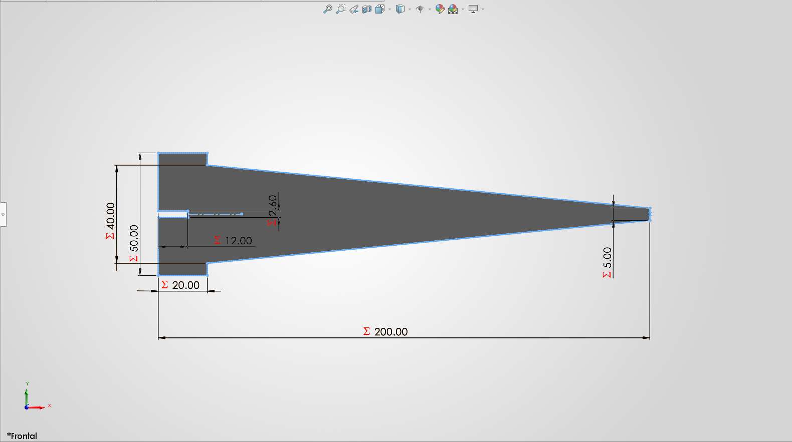
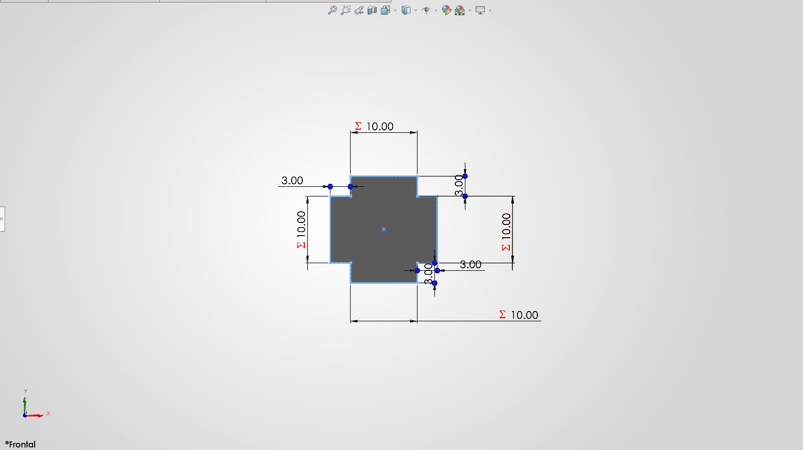
I designed the parts in SolidWorks using parametric variables. Here is the breakdown of the fleet's components.
Desingning the front part.
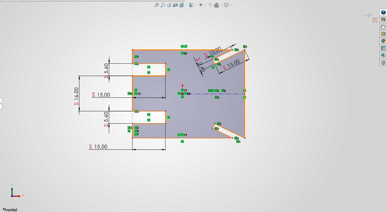
This is the Body Section.
Upper Wings Geometry.
I desing a part to connect the body and wings.
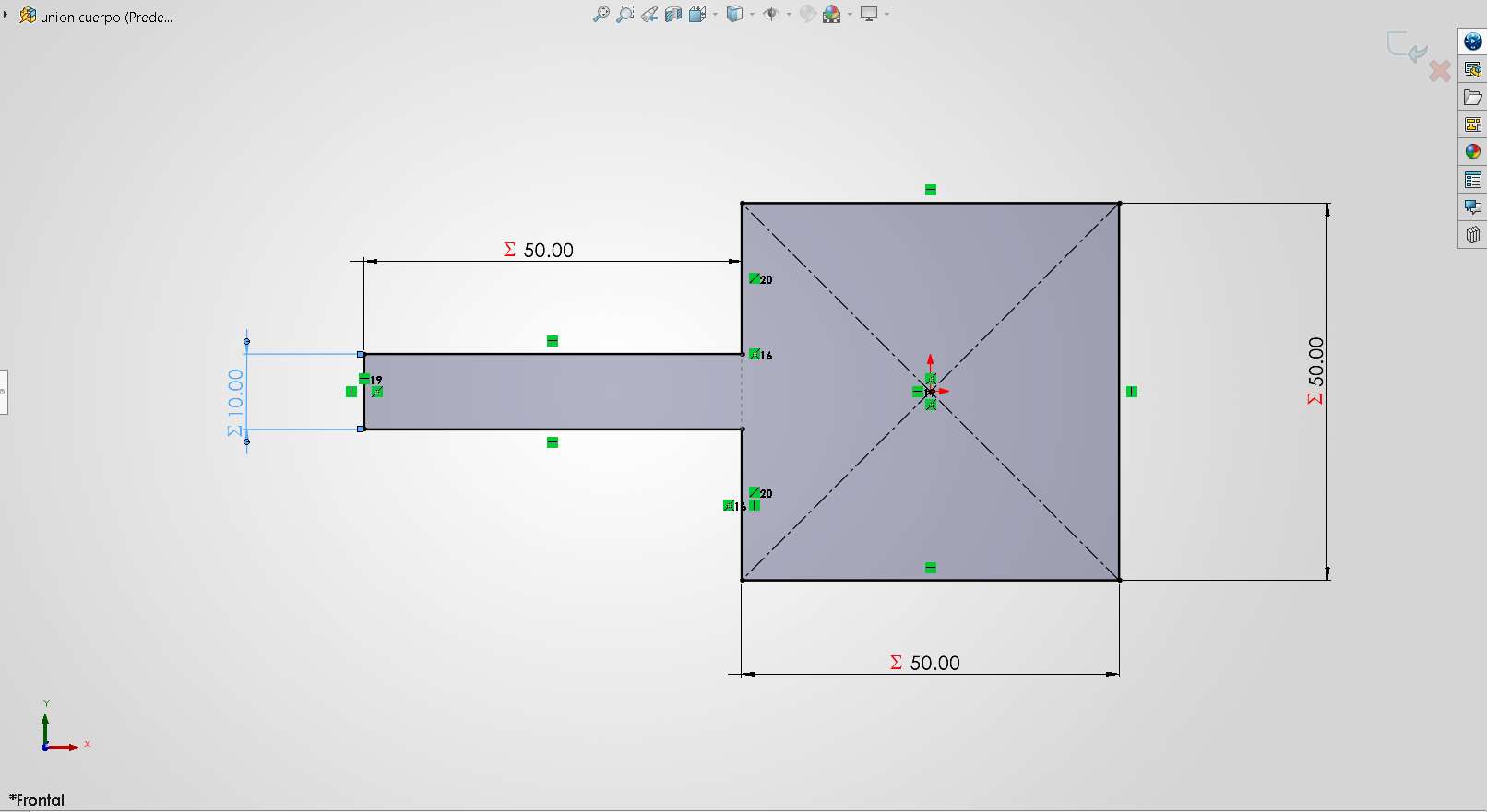
I used a connector to join the body and the front part.
To hold the body together, I designed a horizontal connector.
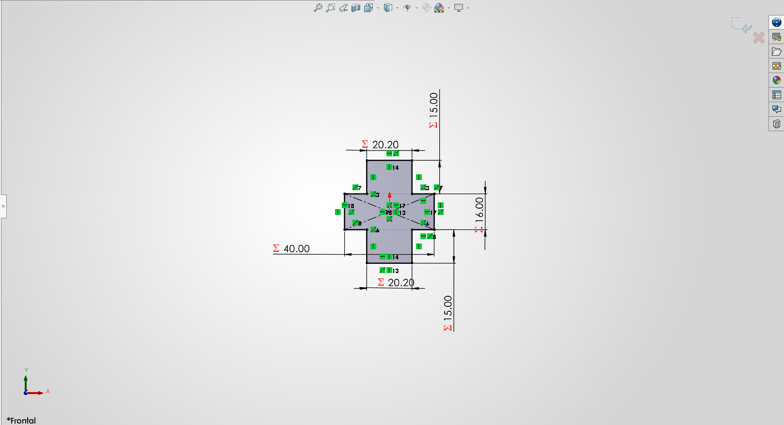
For the front part, I desingned a support piece.
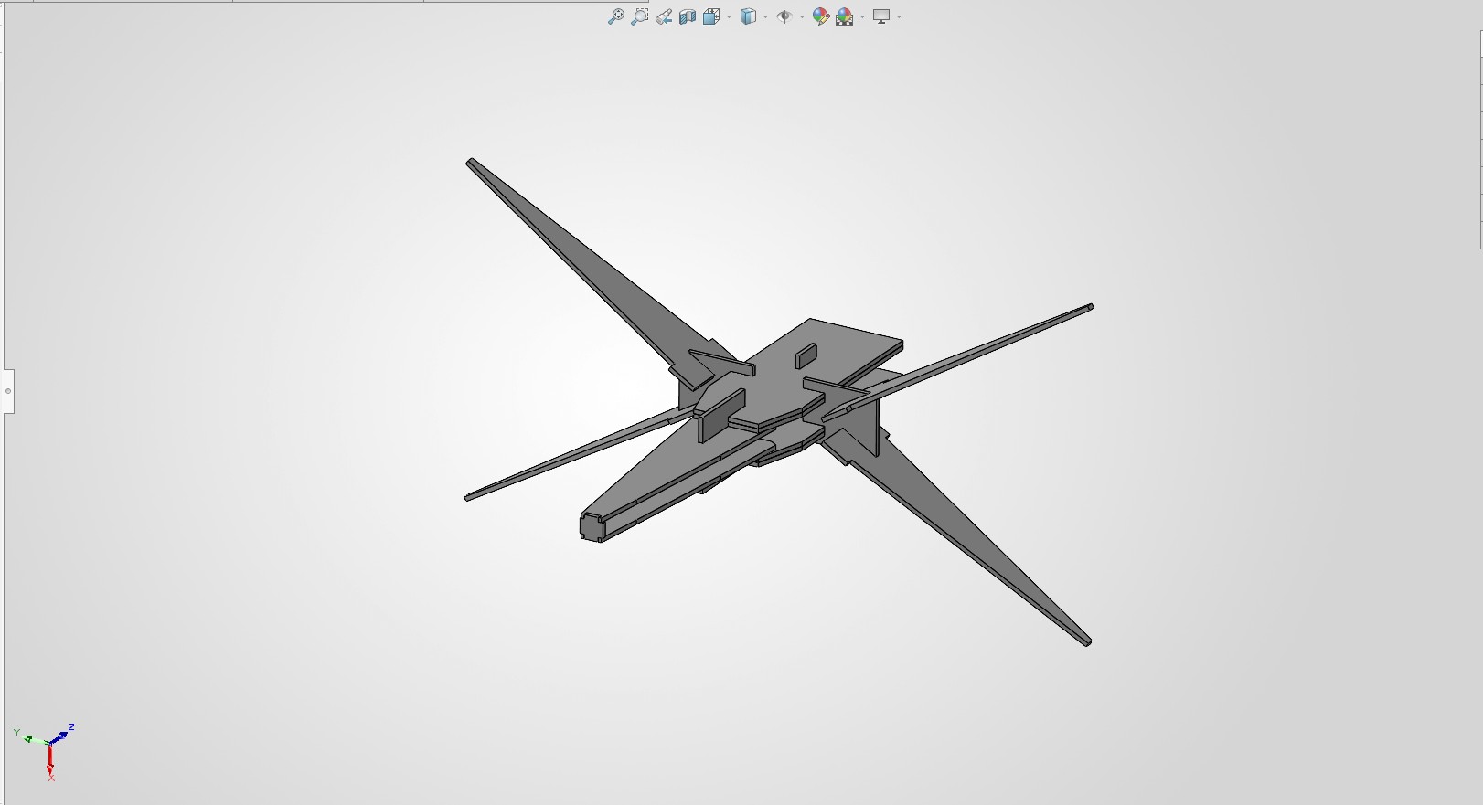
Virtual Assembly Test.
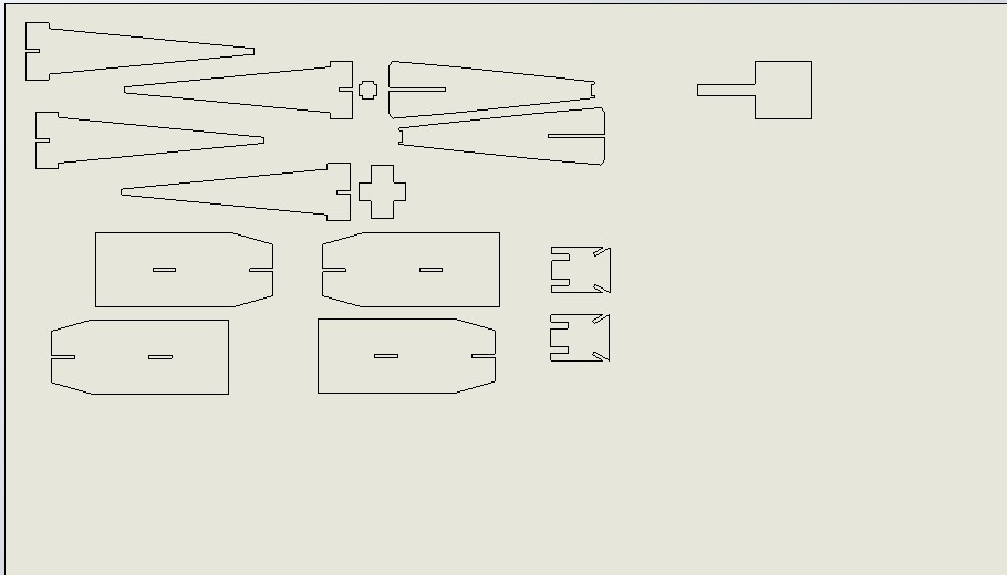
Final DXF. This is how the laser "sees" the design. The kerf compensation is already applied to the slots.
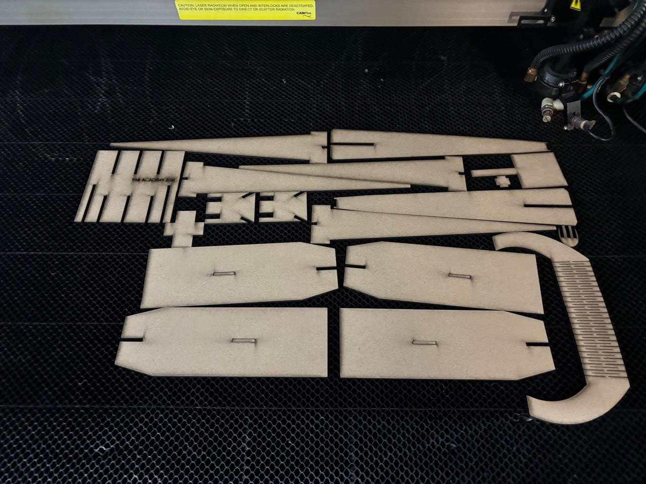
Fresh out of the machine. The MDF edges are burnt but clean.
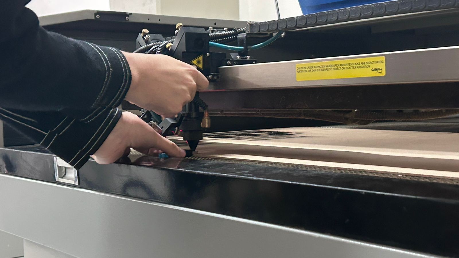
Setting the correct height of the laser.
Machine working, I used this configuration: Speed: 20 / Power: 60.
Video 2. Assembling the X-Wing (Time-lapse)
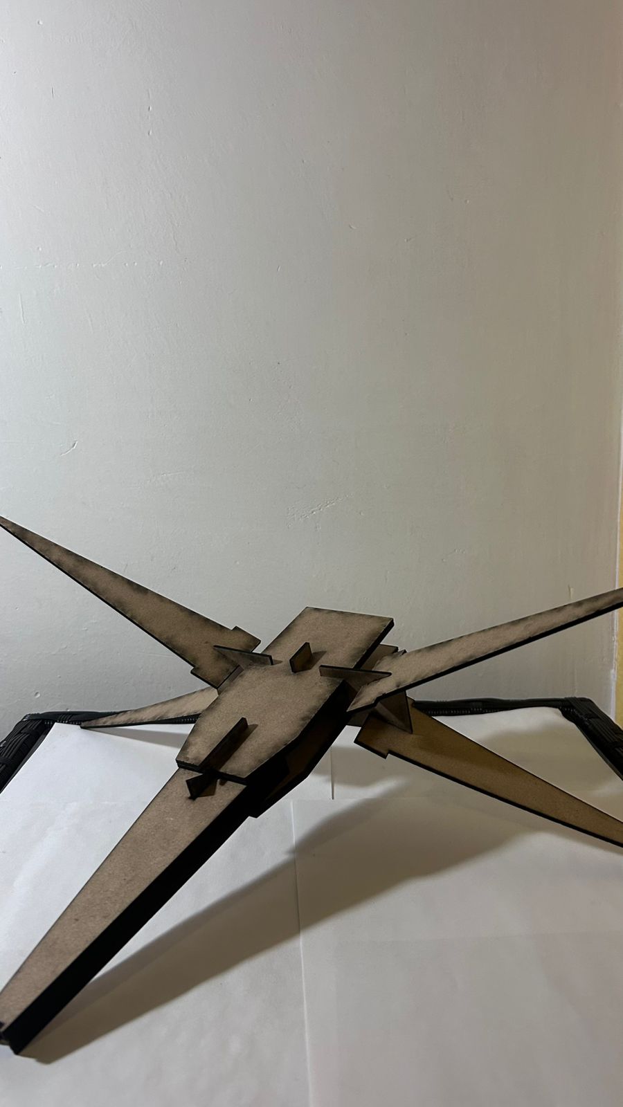
Fig 6. Left View
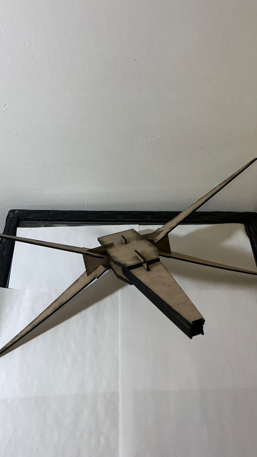
Fig 7. Right View
"I used Gemini to understand how to set up Global Variables in SolidWorks for the slot thickness equation."