Integration Plan for the Final Project
In order to successfully integrate the different areas involved in my final project, I developed the following workflow combining digital fabrication, electronics, embedded programming, and interface development.
- 3D Scanning: Using the knowledge acquired during Week 05: 3D Scanning and Printing, I will scan my hand to obtain a reference model that will allow me to design the glove structure directly over the geometry of my hand.
- Computer-Aided Design (CAD): Using Fusion 360 and the skills developed during Week 02: Computer-Aided Design, I will design the structural and mechanical components of the glove.
- 3D Printing: Using additive manufacturing technologies (FDM 3D printing), I will fabricate the previously designed components of the glove.
- Laser Cutting: I will use this subtractive manufacturing process to fabricate flat components and flexible structural elements of the glove.
- PCB Design and Fabrication: To manufacture the custom electronic board, I will use the xTool machine together with electronic components such as the XIAO ESP32C3 microcontroller, batteries, resistors, and flex sensors.
- Embedded Programming and User Interface Development: The project will include embedded programming for sensor interpretation and a graphical user interface to display the generated words and phrases.
Integration Process for the Final Project
The following section documents the progress and integration workflow of my final project development.
3D Scanning
One of the first steps in the design process was scanning my hand in order to obtain a more accurate reference for designing the glove structure.
The scanner used for this process was the Revopoint POP 2, the same scanner previously used during Week 05: 3D Scanning and Printing. If you would like to see the complete workflow for operating this scanner, you can refer to that week’s documentation.
Once I started the scanning process, I realized that it was extremely difficult to scan my own hand without movement. This became one of the first challenges during the development process.
To solve this issue, I decided to create a physical replica of my hand using molding and casting techniques. For the mold, I used dental alginate, a material commonly used in dentistry, while white plaster was used for the final cast.
I selected dental alginate because it is practical, easy to prepare, and cures very quickly, making it ideal for capturing detailed molds of hands and other body parts. White plaster was selected because it solidifies rapidly and provides a matte white surface, which improves the scanning quality of the 3D scanner.
Dental Alginate
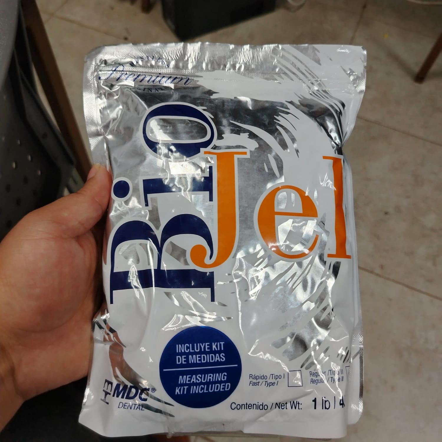
One of the most important properties of this material is its fast curing time, which makes it especially useful for creating molds of upper extremities such as hands.
To prepare the mold, I poured approximately 3.5 liters of water into a container and mixed it with two bags of alginate powder. The mixture was stirred intensively for approximately 100 seconds before submerging my hand into the material.
After approximately 15 minutes, the alginate solidified and formed the mold of my hand.
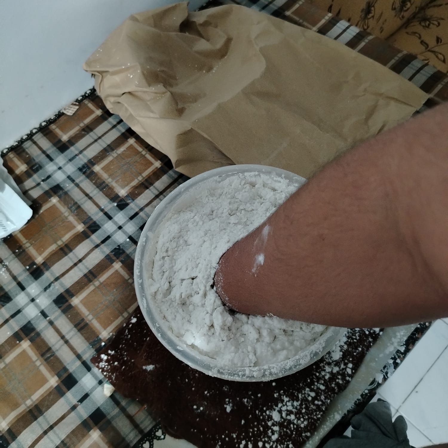
Once the mold was completed, I carefully removed my hand and prepared the white plaster mixture, which was then poured into the mold as shown below.
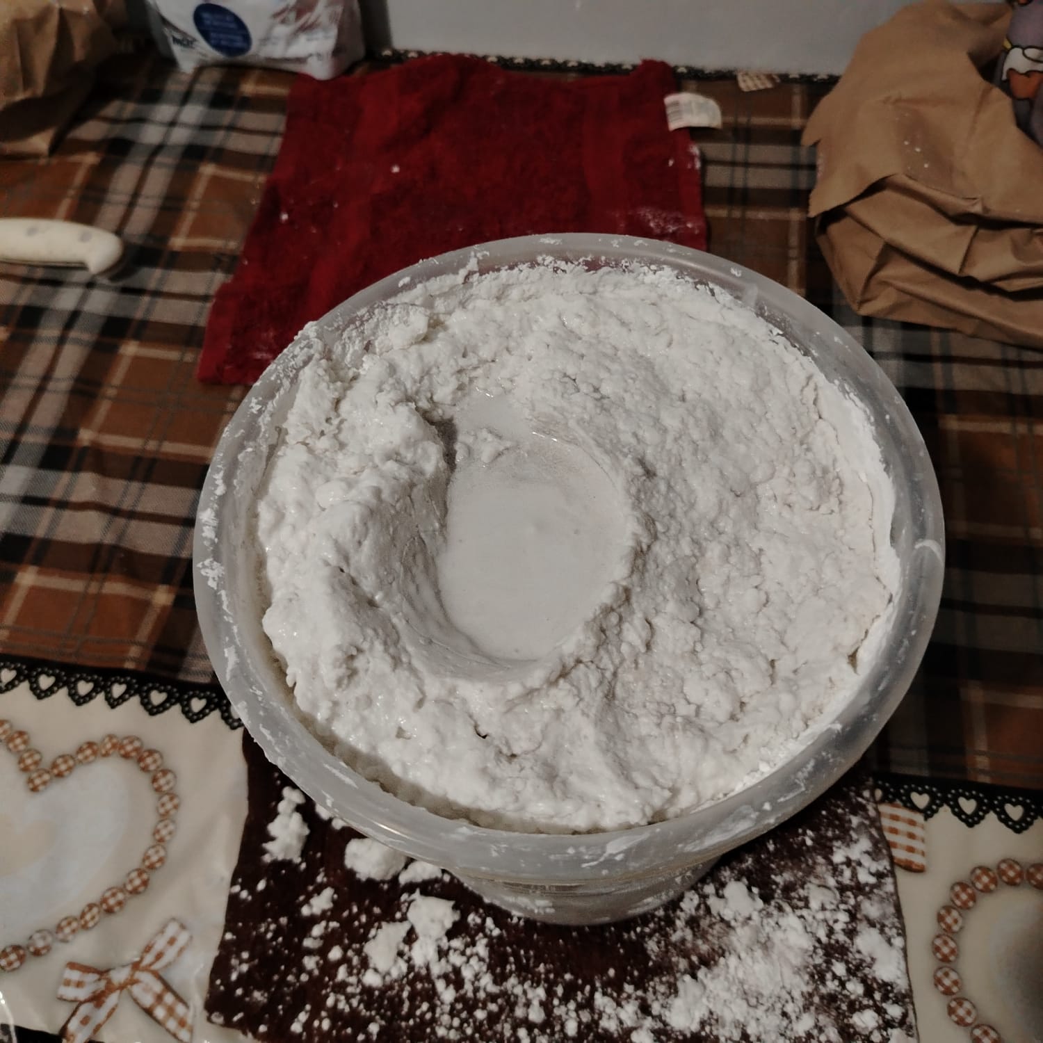
After pouring the plaster, I waited approximately two hours for the material to solidify before beginning the demolding process.
Once the plaster replica was completed, I was finally able to perform the 3D scanning process without unwanted movement. This allowed me to obtain a more stable and accurate scan of my hand geometry.
The following section shows the hand scanning process.
Once the hand was successfully scanned and exported in .OBJ format, I proceeded to the design stage using the scanned geometry as a reference for developing the glove structure.
Computer-Aided Design
During this stage, I explored several design approaches for the glove. The process evolved from an initially rigid and highly mechanical concept toward a simpler, lighter, and more comfortable wearable design.
First Version
The following image shows the initial conceptual design of the first version of the glove.
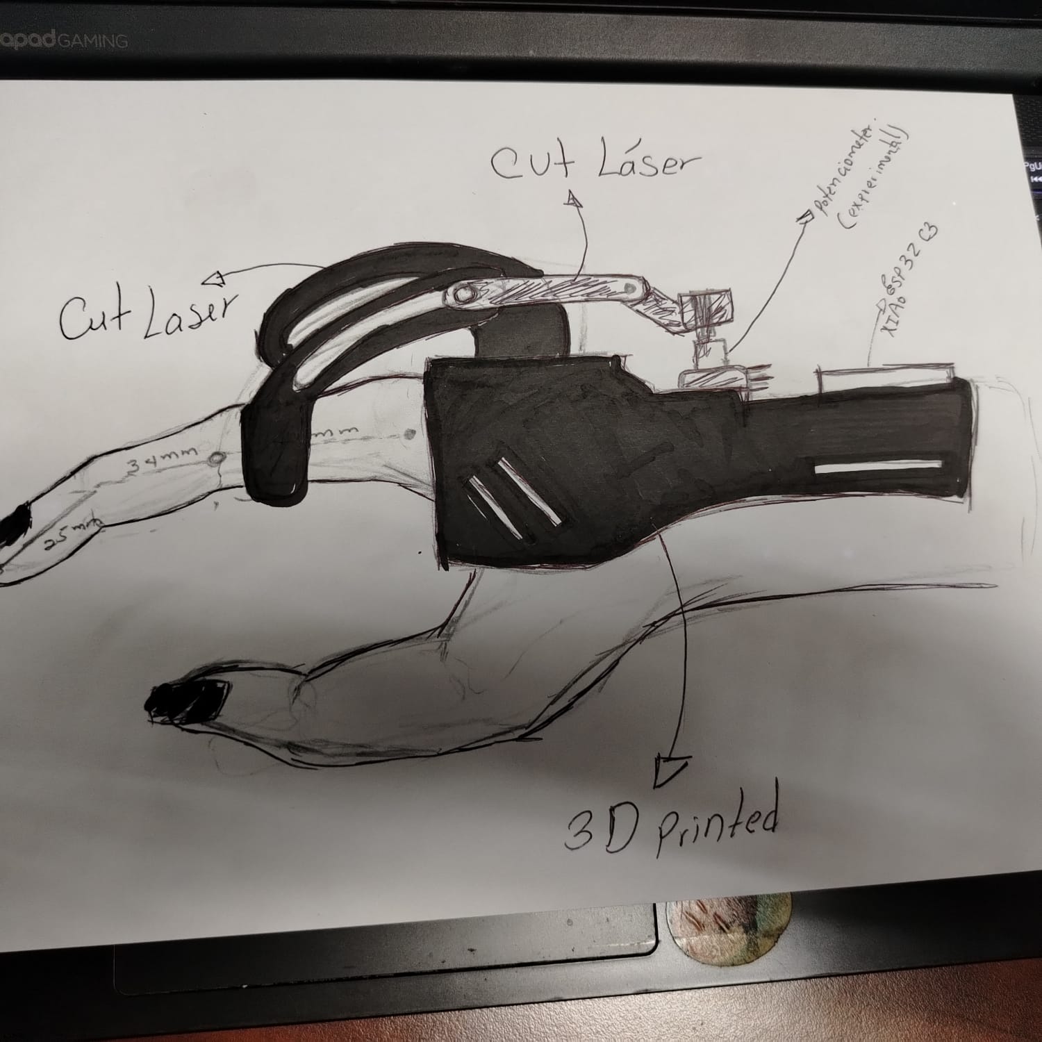
As shown in the image, the first approach was based on a mechanical exoskeleton concept composed of articulated components. During this phase, I also experimented with the possibility of using potentiometers instead of flex sensors in order to evaluate whether a lower-cost sensing alternative could be implemented.
Potentiometers are considerably cheaper compared to flex sensors, so the idea was to mechanically convert finger movement into rotational motion capable of driving the potentiometer shaft. Additionally, I attempted to integrate flat components into the design so they could later be fabricated using laser cutting techniques.
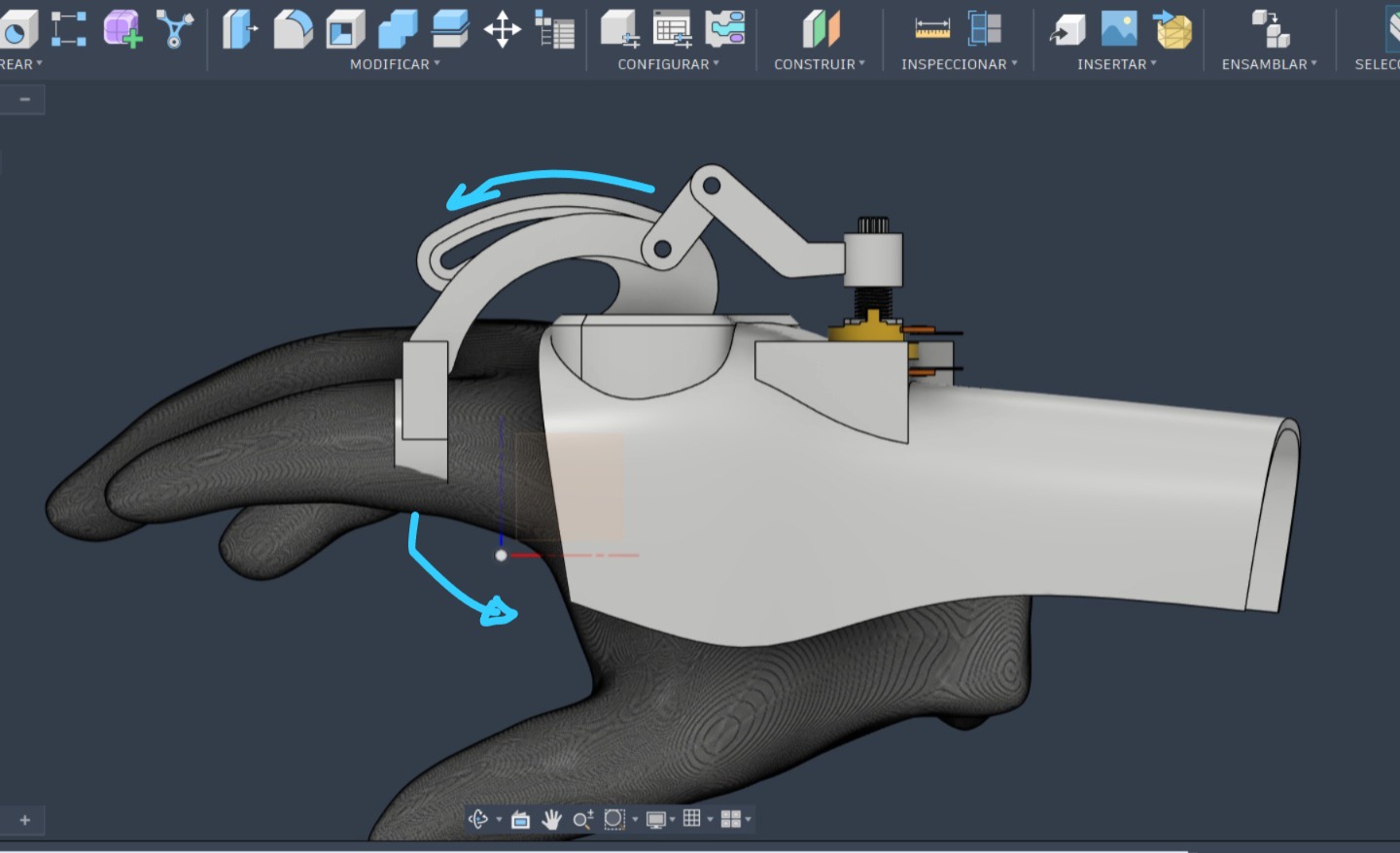
As observed in the CAD model, the mechanism was designed so that finger flexion would activate a linkage system connected to the potentiometer knob. This rotational movement would generate analog values that could later be interpreted by the XIAO ESP32C3 microcontroller.
To develop this design, I had to study the kinematics of the human hand, especially the movement of the finger phalanges during flexion and extension. The following research document was particularly useful for understanding these movements: View Reference
After completing the initial design, I rapidly fabricated a prototype using 3D printing in order to evaluate the functionality of the mechanism.
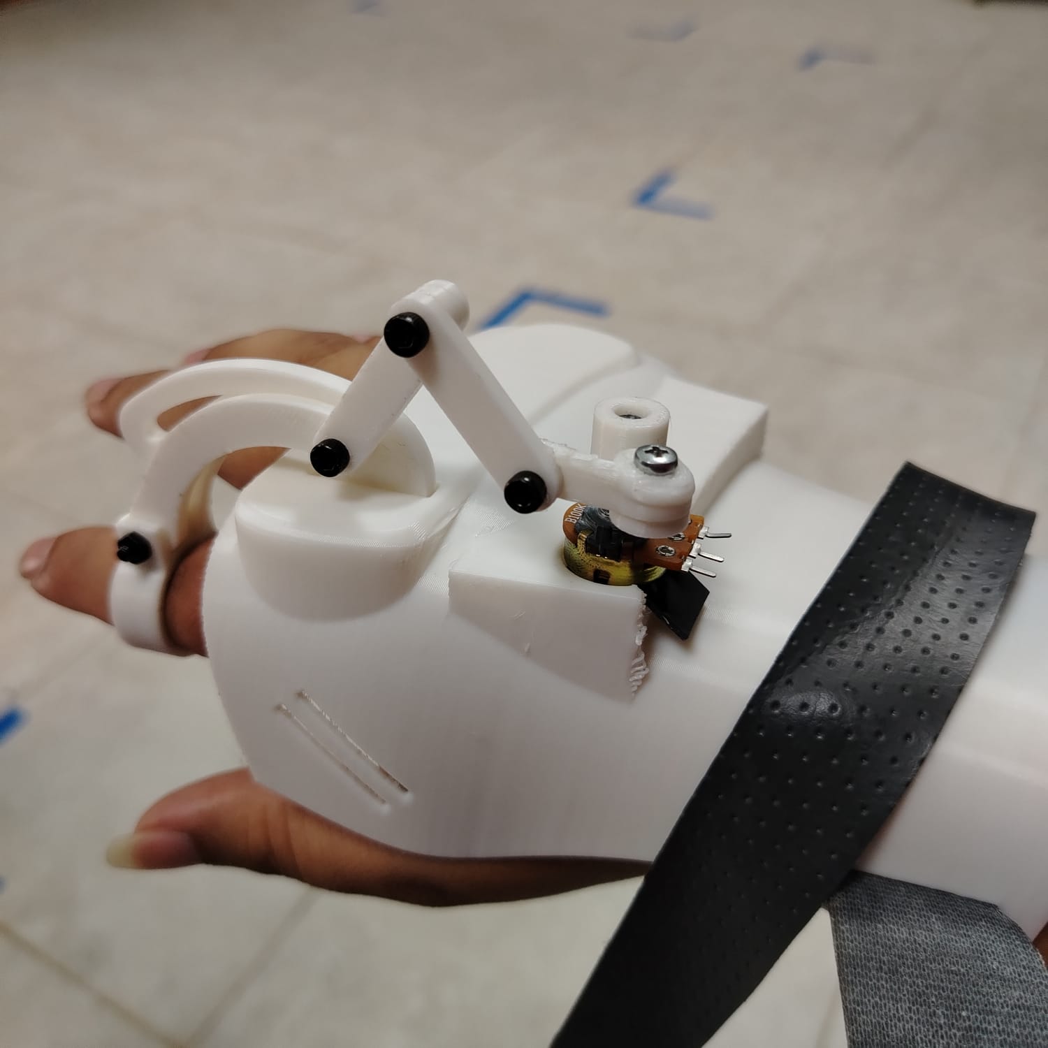
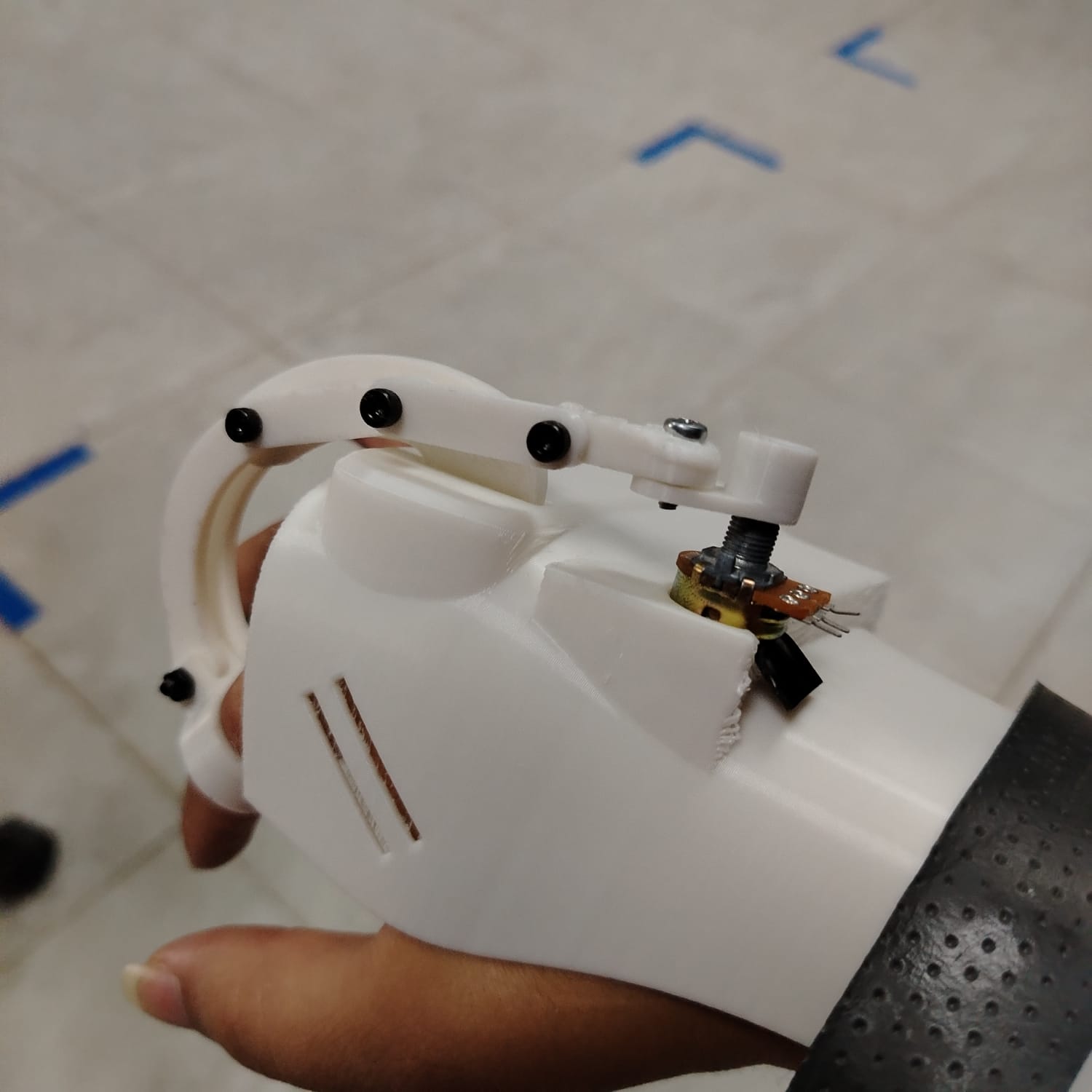
Once the prototype was printed, I tested it directly on my hand using a potentiometer to verify whether the linkage system moved freely. The mechanism worked correctly and produced rotational movement; however, I noticed that the system generated resistance during finger movement and felt excessively rigid for the intended application.
During a meeting with my local evaluator, one of the main observations was that the design appeared too mechanical and uncomfortable for generating hand gestures naturally. After testing the system myself, I agreed with this feedback.
Another issue identified was the physical space occupied by the potentiometers around the wrist area. Due to these limitations, I decided to completely redesign the system and return to the original idea of using flex sensors instead of potentiometers.
Second Version
Developing the second version required redesigning the project from the ground up. This time, the focus shifted toward creating a softer, more ergonomic, and wearable structure.
The following image shows the updated conceptual design for the second version of the glove.
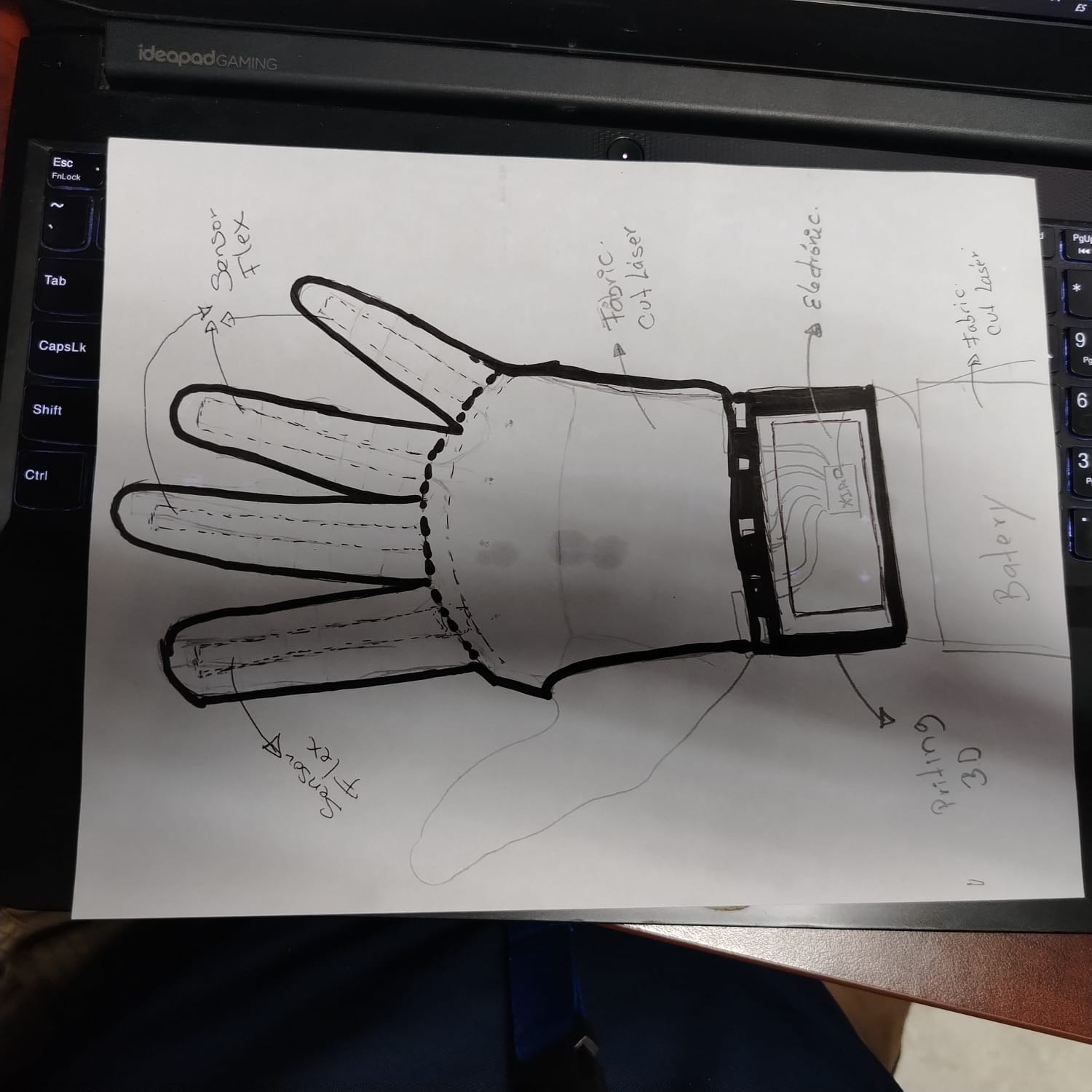
In this new approach, I decided to integrate textile materials into the glove structure. The main materials considered were vinyl fabric and synthetic leather, which would provide greater flexibility and comfort compared to the rigid exoskeleton structure of the first version.
Additionally, a wrist-mounted enclosure was designed to contain the electronic circuitry and the custom PCB that will be fabricated later in the project.
After meeting with my evaluator, I also developed a new project timeline and integration strategy. The updated schedule can be found in the Final Project section.
In addition, I had to develop a new workflow and integration strategy for the final project in order to better organize the fabrication, electronics, and assembly stages.
New Integration Plan for Version 2
- Develop a hand-drawn conceptual sketch of the integrated system to visualize the overall appearance and functionality of the final prototype.
- Take accurate measurements of my fingers, phalanges, and wrist to ensure proper ergonomic fitting.
- Design the 3D model of the glove support structure, which will contain the main electronic components and microcontroller.
- Develop the 2D cutting layouts and fabrication plans for the flexible glove structure.
- Fabricate the flat components of the glove using laser cutting technology.
- 3D print the wrist-mounted enclosure that will house the microcontroller and electronic system.
- Sew the different fabric sections together to gradually build the glove structure and integrate each finger assembly. Since I do not have previous sewing experience, this stage became both a technical and personal challenge.
- Design and fabricate the electronic system of the glove, including sensor integration and signal processing.
- Develop the embedded programming and graphical user interface responsible for interpreting and displaying the generated words or phrases.
Explanation of the New Integration Plan
Once the conceptual design was clearly defined and the measurements of my fingers and wrist had been taken, I proceeded to the digital modeling stage. The first component developed was the 3D structure that would support the main electronic elements of the glove, including the PCB and sensor connections.
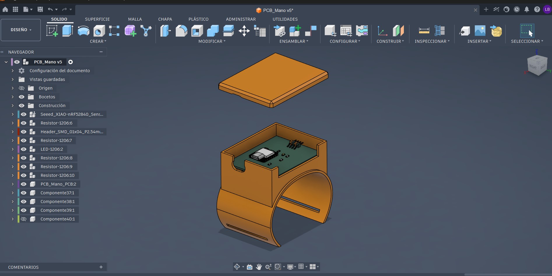
As shown in the animation, the structure consists of three main parts designed to be assembled together. Between these layers, I plan to integrate a mesh fabric material.
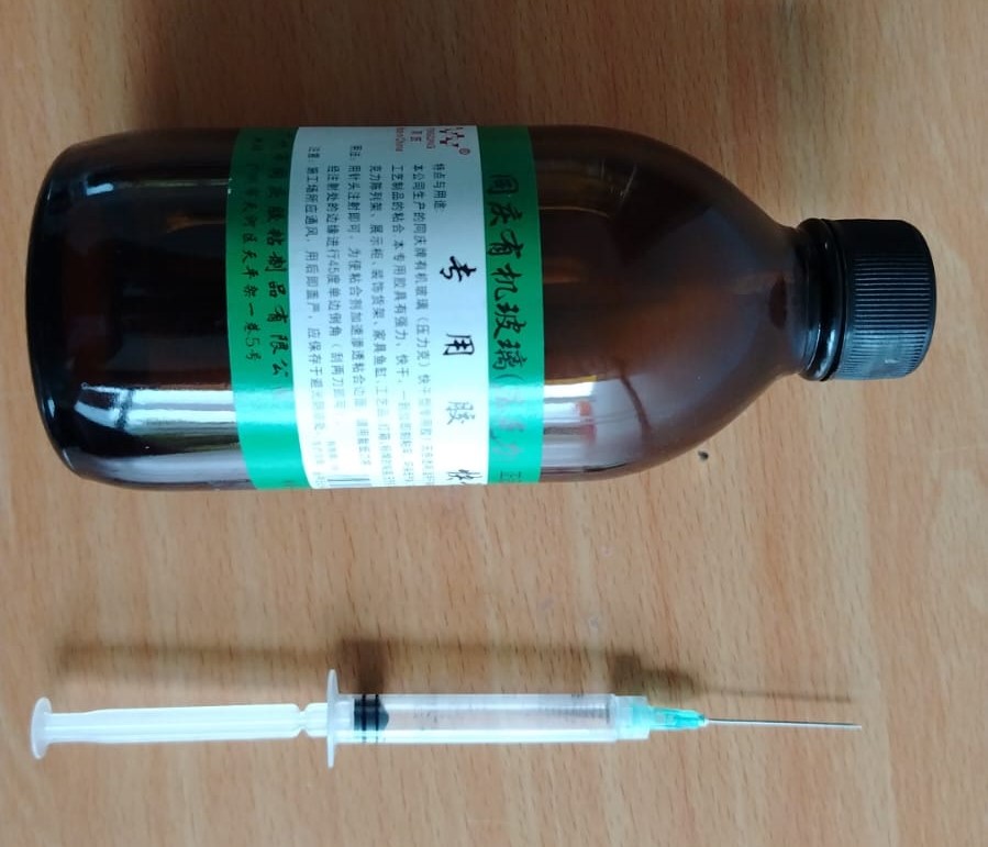
Mesh fabric was selected because its perforated structure works well when combined with plastics such as PLA or PETG. To bond these materials together, I intend to use Weld-On acrylic cement.
This adhesive chemically reacts with the PETG surface, partially softening the plastic. Because the mesh fabric contains large openings, the softened material can flow through the fabric and bond with the upper layer, creating a sandwich-like structure that mechanically joins the plastic and textile materials together.
Later in the process, I began designing the 2D cutting patterns that would form the flexible structure responsible for bending the flex sensors together with finger movement.
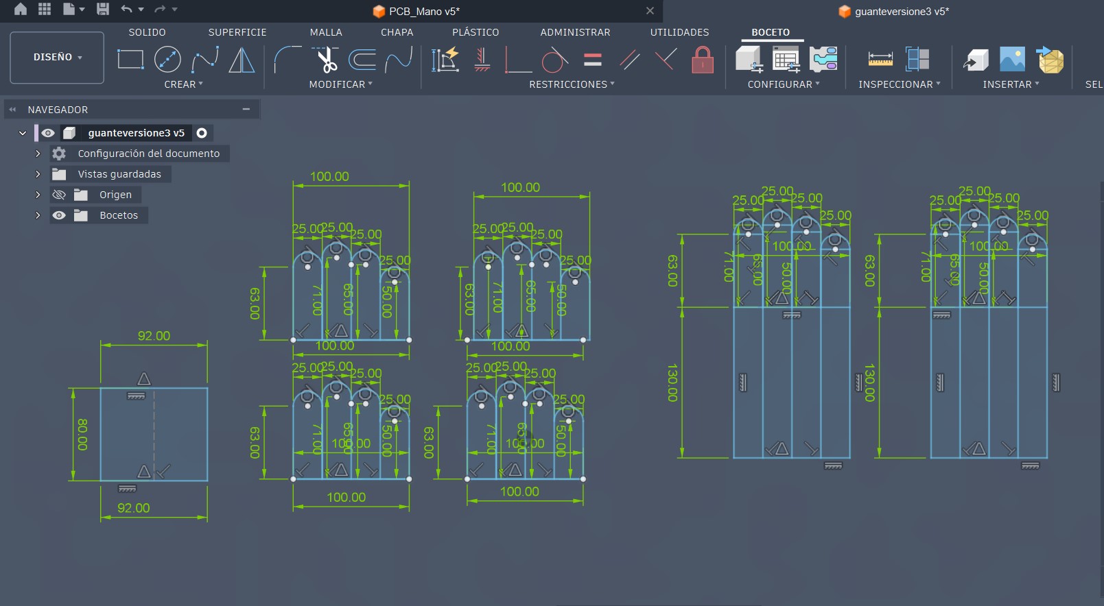
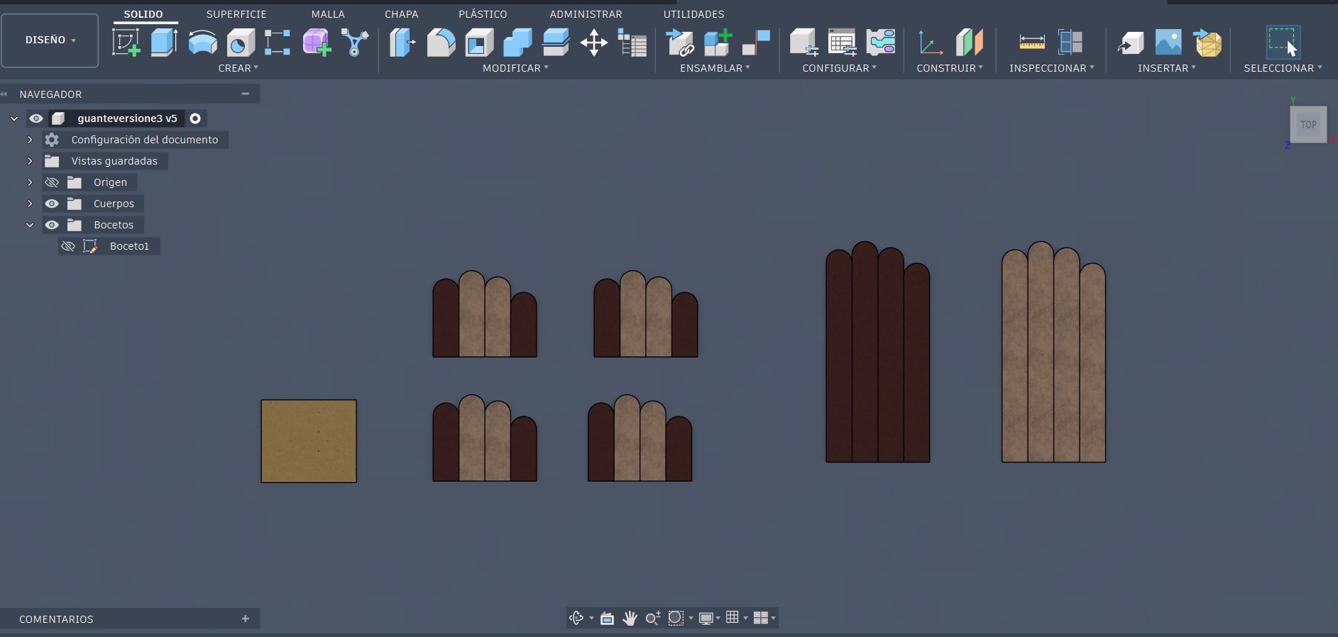
Once the design stage was completed, I proceeded to the fabrication process using several digital fabrication machines and manufacturing techniques.
The main machines used during this stage were:
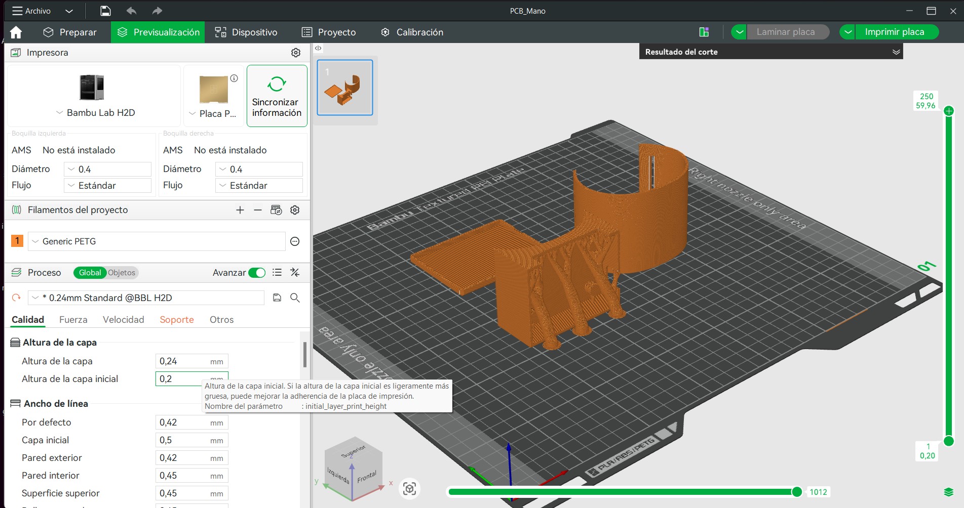
- Bambu Lab H2D FDM 3D printer
- Fenix FX-CMA 1309 K-A laser cutter
- Brother SE1900 multifunction sewing and embroidery machine
- xTool IR Fiber Laser for PCB fabrication
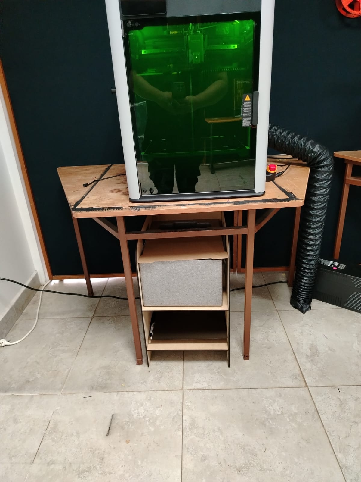
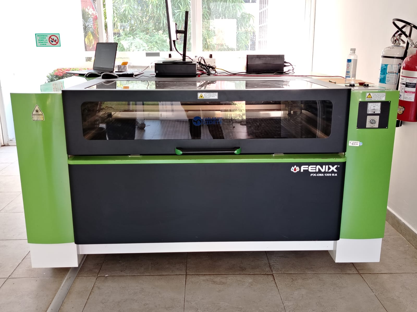
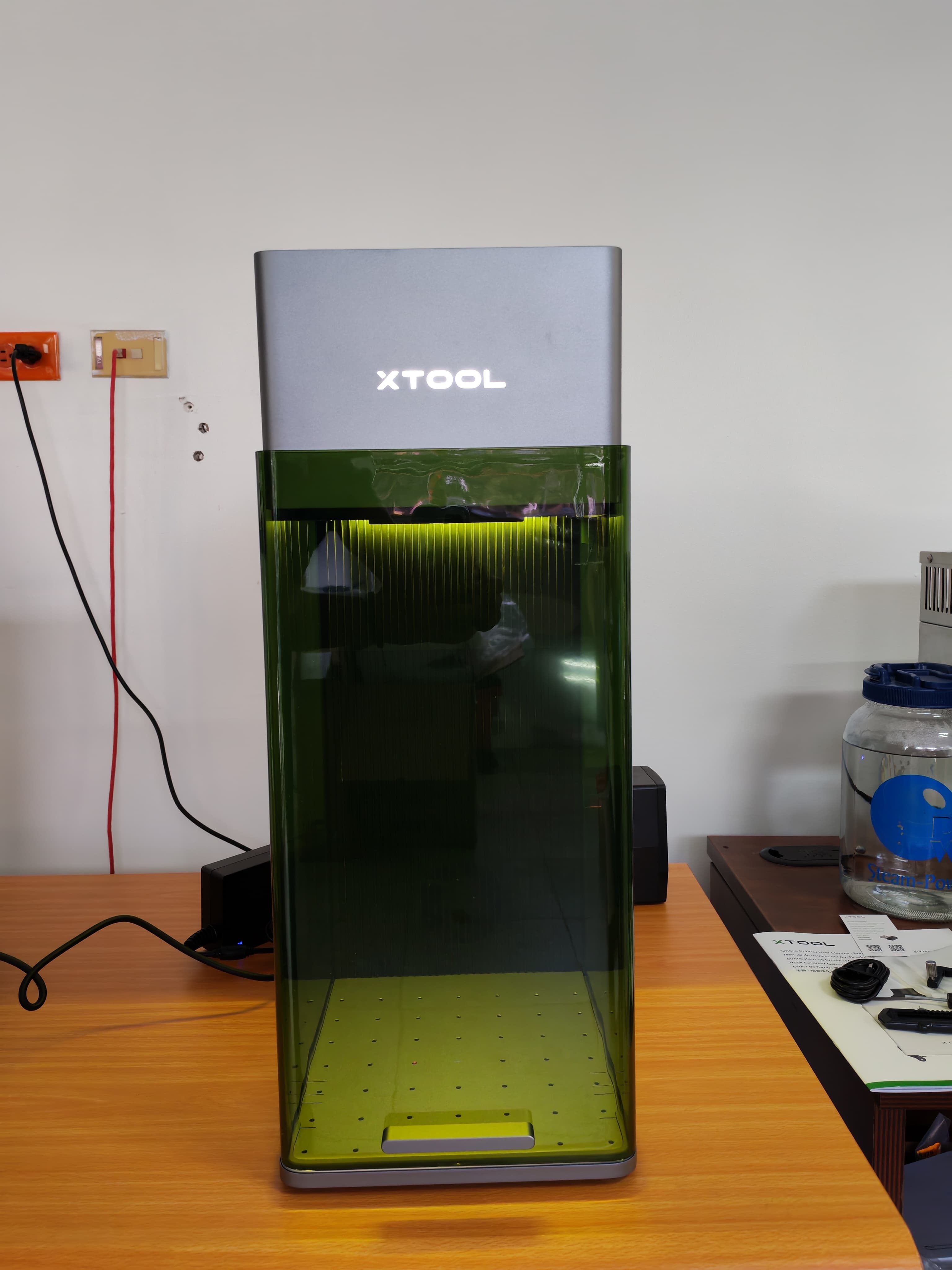
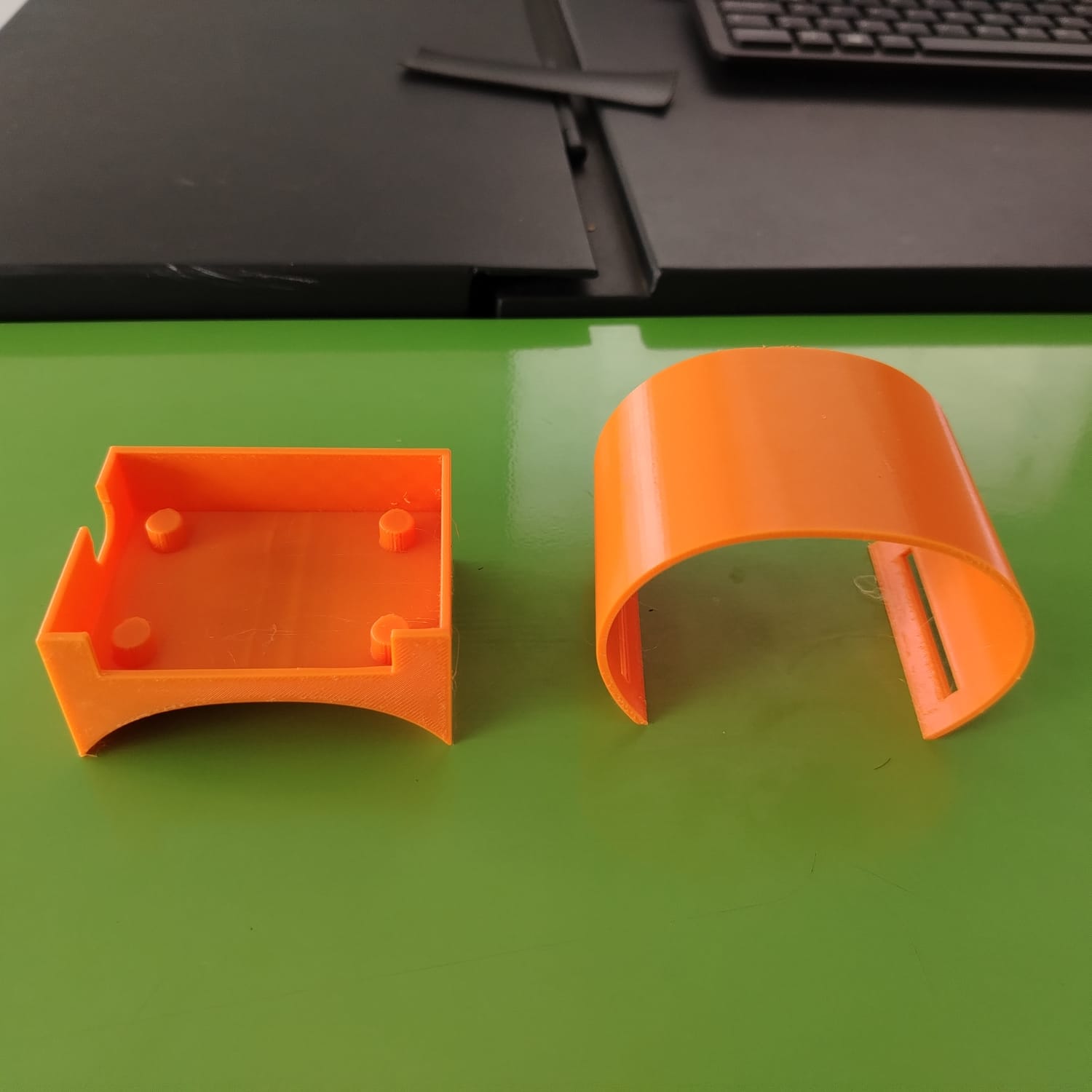
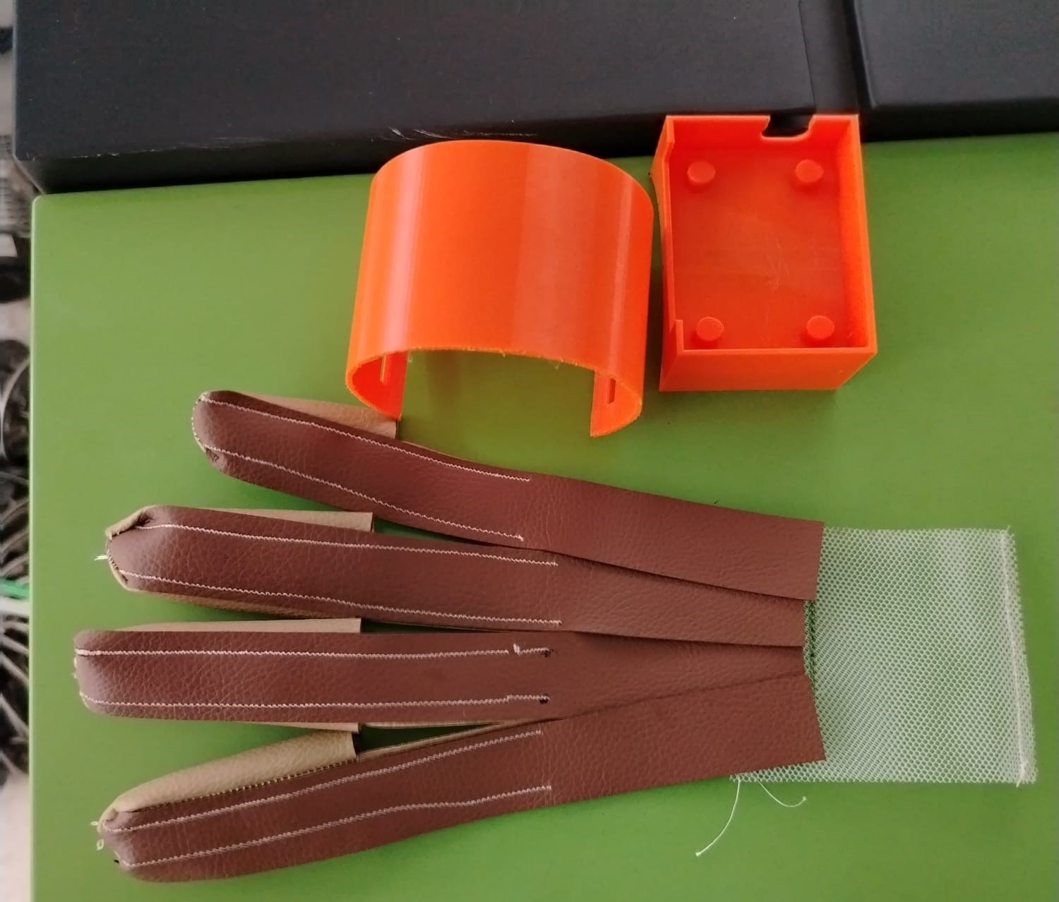
The first fabrication step was the 3D printing of the wrist-mounted structure that will support the PCB and the main electronic components of the glove.
Result of the 3D printed component.
After completing the printed structure, I proceeded with the laser cutting process for the textile components of the glove.
During this stage, I experimented with two different types of materials. Initially, I used vinyl fabric; however, the material was too thick and difficult to sew. Due to this limitation, I later switched to synthetic leather (cuerina), which provided a more flexible and aesthetically pleasing result.

Once the textile components were cut, I moved on to the sewing process, which became one of the most challenging stages of the project due to my lack of previous sewing experience.
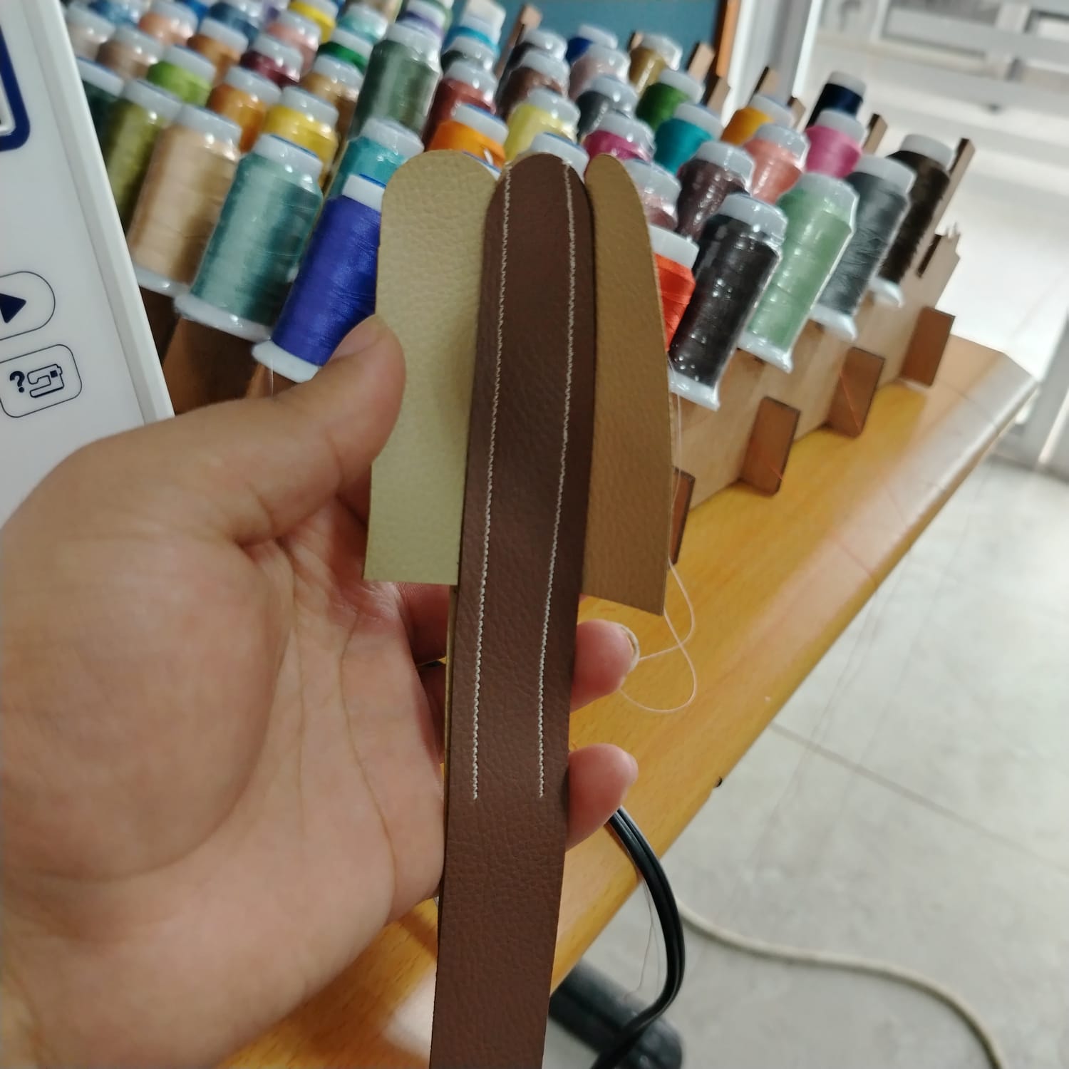
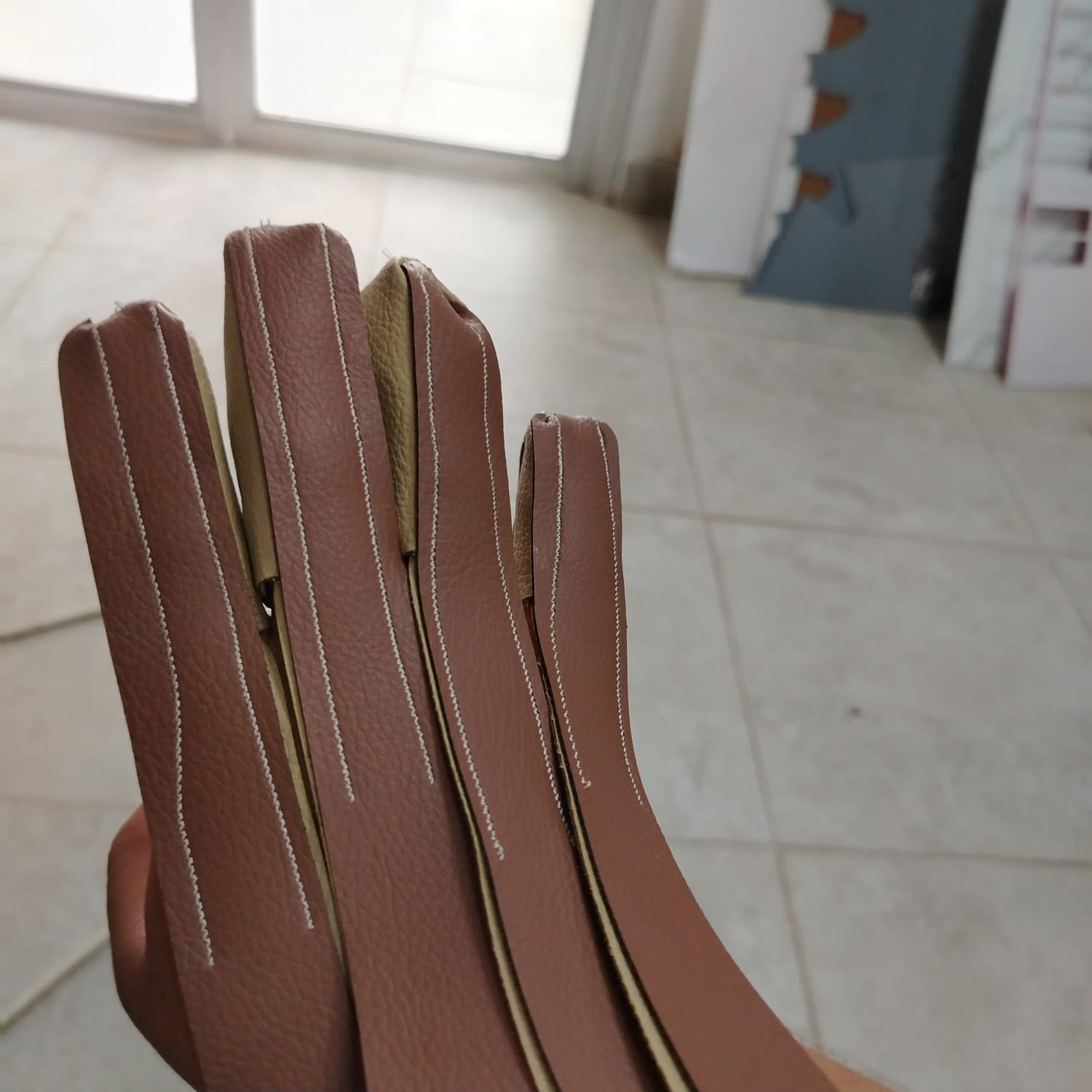
As observed in the images, internal channels were intentionally integrated into each finger structure. These channels will later be used to insert and protect the flex sensors inside the glove assembly.
The next stage involved integrating the plastic structure with the textile components. As previously mentioned, mesh fabric and Weld-On acrylic cement were used during this process.
The first step consisted of sewing the mesh fabric directly onto the synthetic leather structure, as shown in the following images.
At this point, the integration between the textile and plastic structures was progressing as shown below.
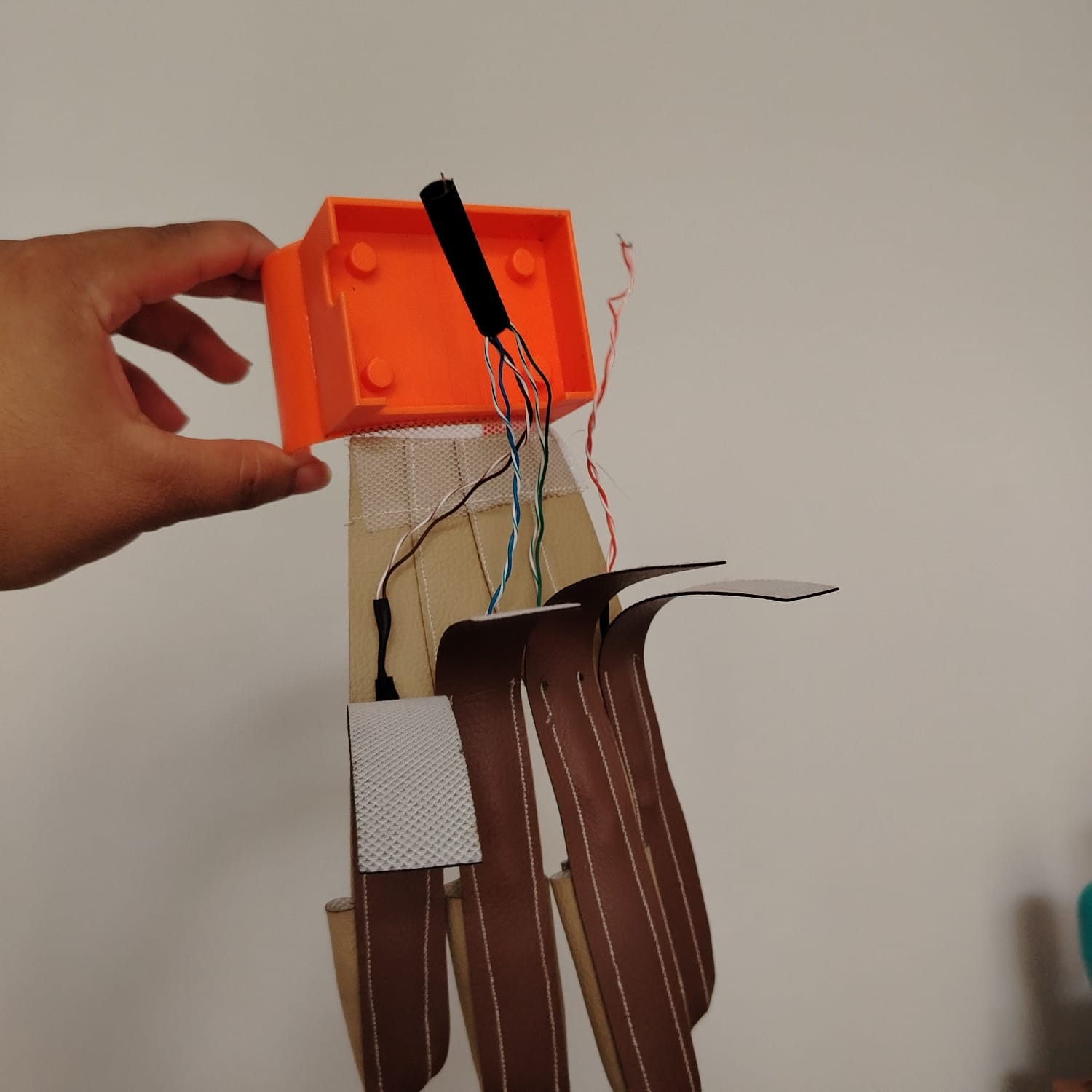
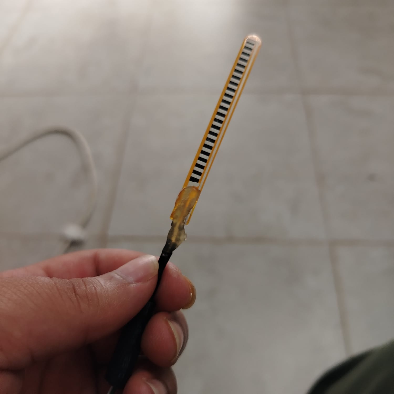
To prepare the flex sensors for installation, I soldered network cables to each sensor and reinforced the weakest connection points using hot glue. This reinforcement was added to reduce mechanical stress and improve durability during repeated bending cycles.
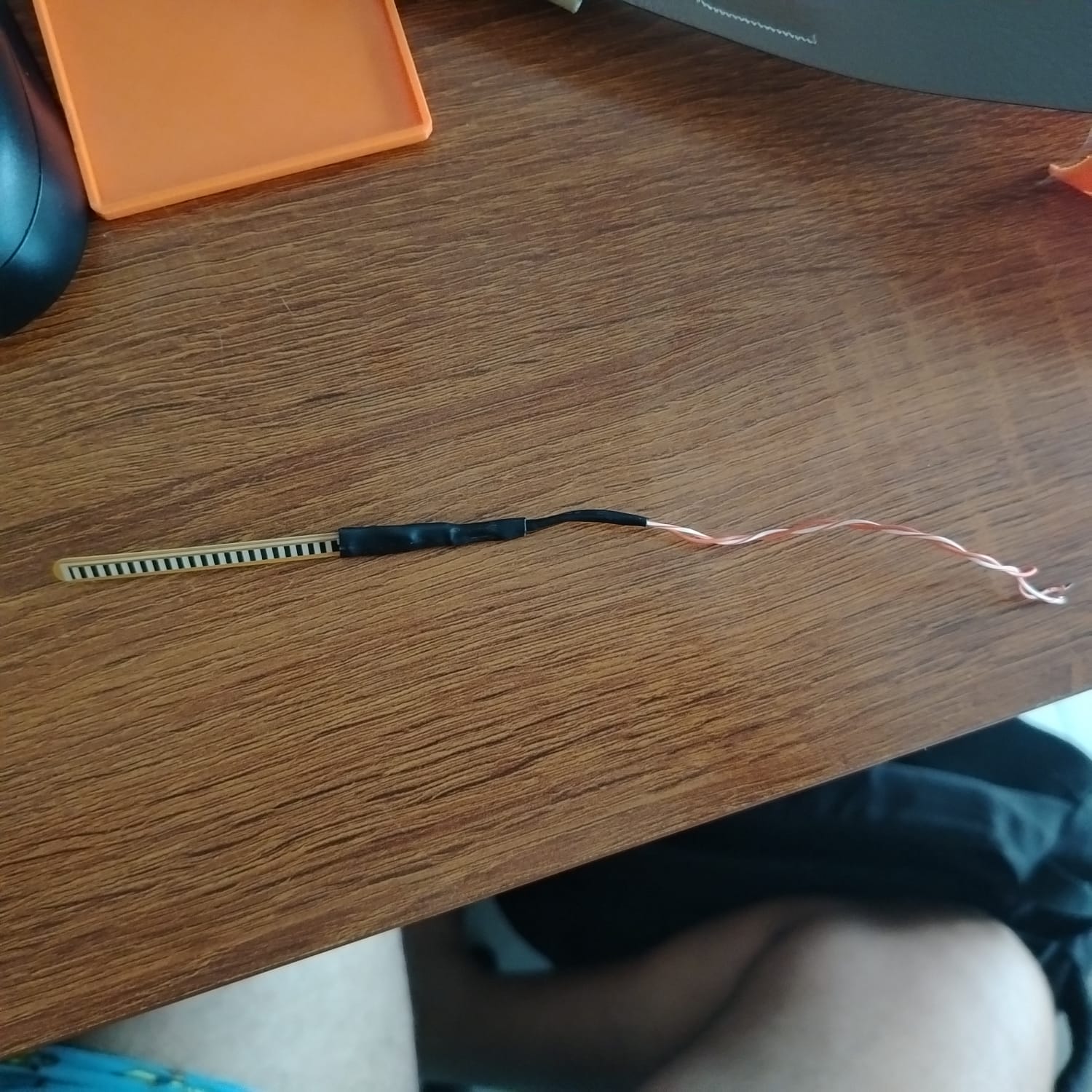
The flex sensors will be installed inside the previously designed internal channels to keep the system compact and protected.
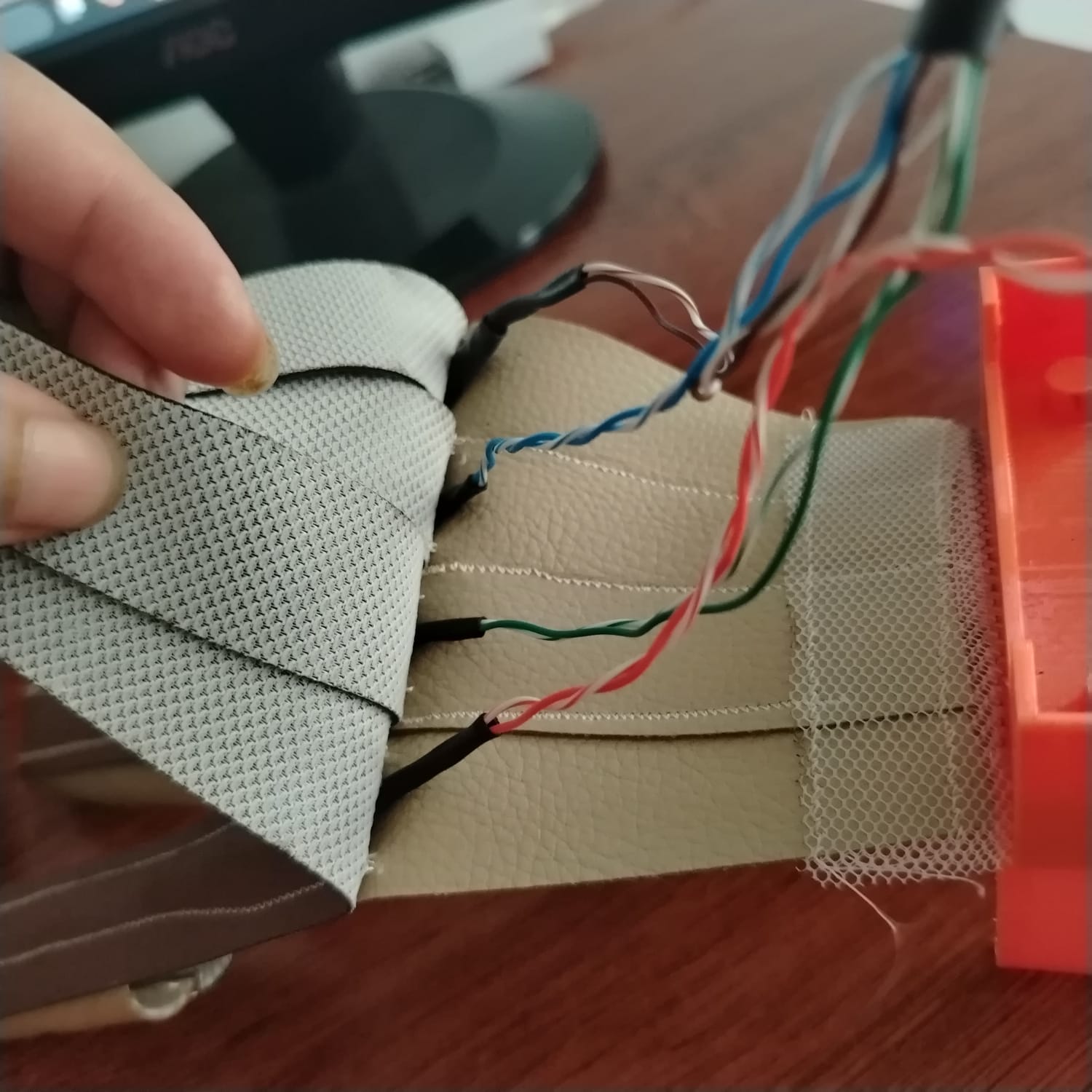
To complete the structural integration and improve cable management, Velcro fabric straps will be used to secure loose sections and conceal the wiring inside the glove assembly.
PCB Fabrication
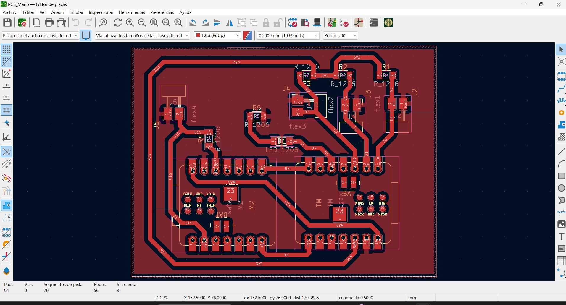
Note: In this PCB design, jumper wires were required to connect several GND traces. I attempted multiple routing configurations for a single-layer design, but due to space limitations, implementing jumper connections became the most practical solution.
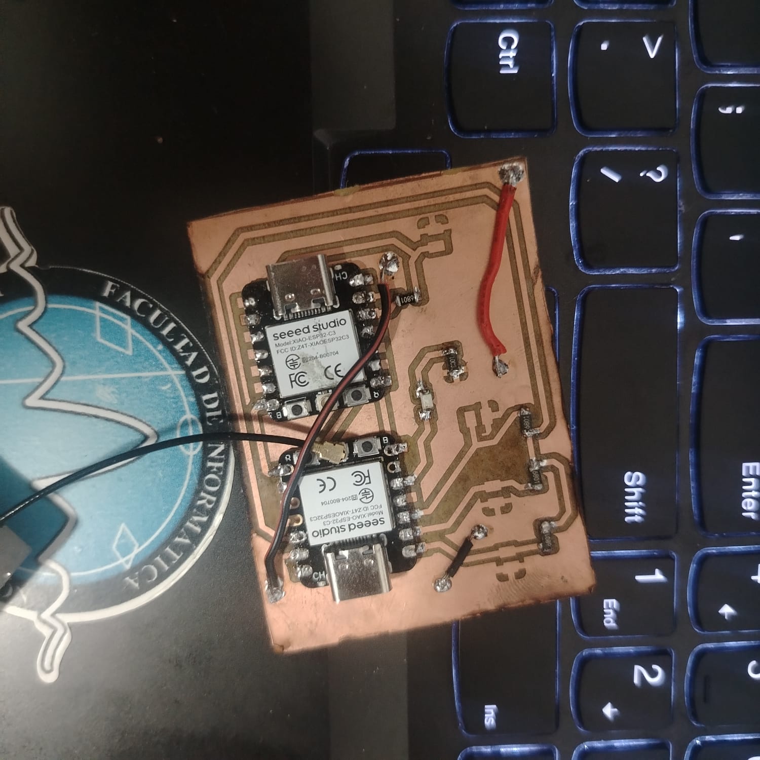
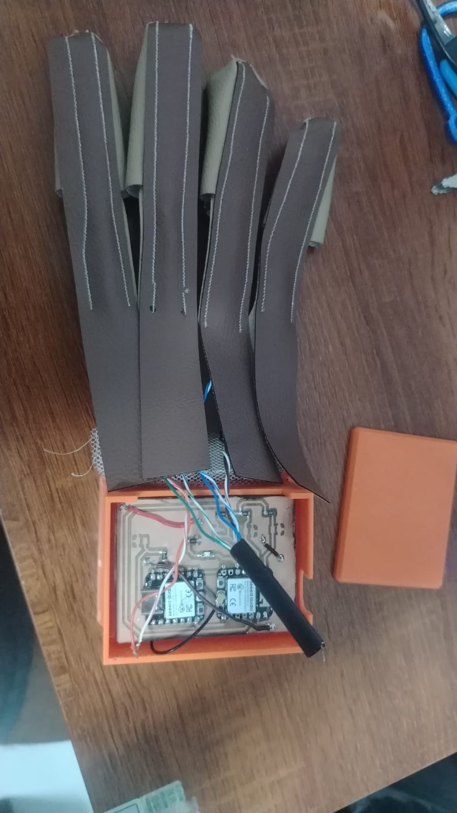
At the current stage, the structure and electronics integration are mostly completed. The remaining major task is the programming stage.
It is important to mention that the system currently uses two XIAO ESP32C3 boards. Each board provides four ADC channels; however, the A3 pin became unstable and generated erratic analog readings during testing.
Due to this limitation, I decided to use a second XIAO ESP32C3 board configured as a slave device and establish communication between both boards through UART communication. This solution was implemented because I only had access to two XIAO boards and no additional development boards were available.
However, this approach did not work as expected. After assembling and testing the system, one of the boards was not properly recognized by the microcontroller, making it impossible to use both boards simultaneously. One possible solution would have been to incorporate an external ADC (Analog-to-Digital Converter) to increase the number of available analog inputs. However, I did not have access to an ADC module at the time of development. As a result, I decided to simplify the design and continue the project using only three active flex sensors.
For power supply, the system will use a power bank .
To learn more about this project, visit the Final Project page.