Group assignment
Objective
-
Test the design rules for your 3D printer(s)
-
Document your work on the group work page and reflect on your individual page what you learned about characteristics of your printer(s)
Here I share the link to my group assignment.
Explaind what you learned from testing 3d printers
What I learned from testing the printers is that, whenever a printer is used for the first time, it is essential to perform test prints. These tests help identify important parameters such as the maximum overhang angle, which generally should not exceed 45 degrees. In addition, the printing temperature varies depending on the material used, and proper bed leveling is critical to achieving good print quality. Evaluating joint tolerances is also essential.
Furthermore, orienting the parts at an angle during printing helps improve the mechanical strength of the parts and also affects the amount and placement of the required support structures.
Additionally, I learned that FDM printing allows bridging distances of approximately 5 to 20 mm. The exact values of these parameters depend on both the printer and the material being used.
Indivual assignment
For this week, the assignment individual was to design and 3D print an object, and additionally, to generate a 3D model using 3D scanning technology.
Design and 3D print an object
Process of Disign 3D
To develop the design, I used Fusion 360 software.
One of the design requirements was that the object should not be easy to manufacture using subtractive processes, and that additive manufacturing would be the most suitable method to produce it.
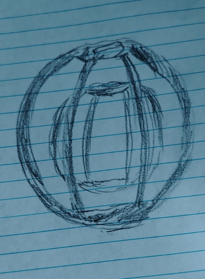
During the conceptualization process of a 3D object that would be difficult to manufacture using subtractive methods, the idea emerged to design a hollow sphere containing a smaller sphere inside. Both spheres incorporate a geometric pattern, resulting in a complex, enclosed geometry that is practically impossible to produce using subtractive manufacturing processes.
Once the idea was defined, I quickly sketched it on paper to preserve the original concept before starting the digital modeling process.
conceptualization of a 3D object
Once I had a clear idea of what I wanted to 3D print, the next step was to begin modeling my object in Fusion 360.
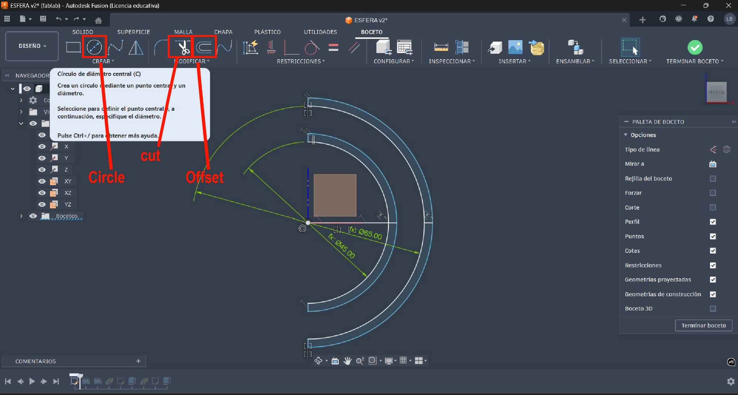
Once in the software Fusion 360, I created a new sketch on the XZ plane. In this sketch, I drew two concentric circles: one with a diameter of 65 mm and the other with a diameter of 45 mm.
An outward offset of 2.3 mm was applied to both circles, and using the trim tool, the unnecessary lines were removed. The final sketch result is shown in the image below.
Once the design profiles were created, the next step was to apply the revolve tool to both profiles. First, the revolve operation was applied to the inner profile, as shown in the image.
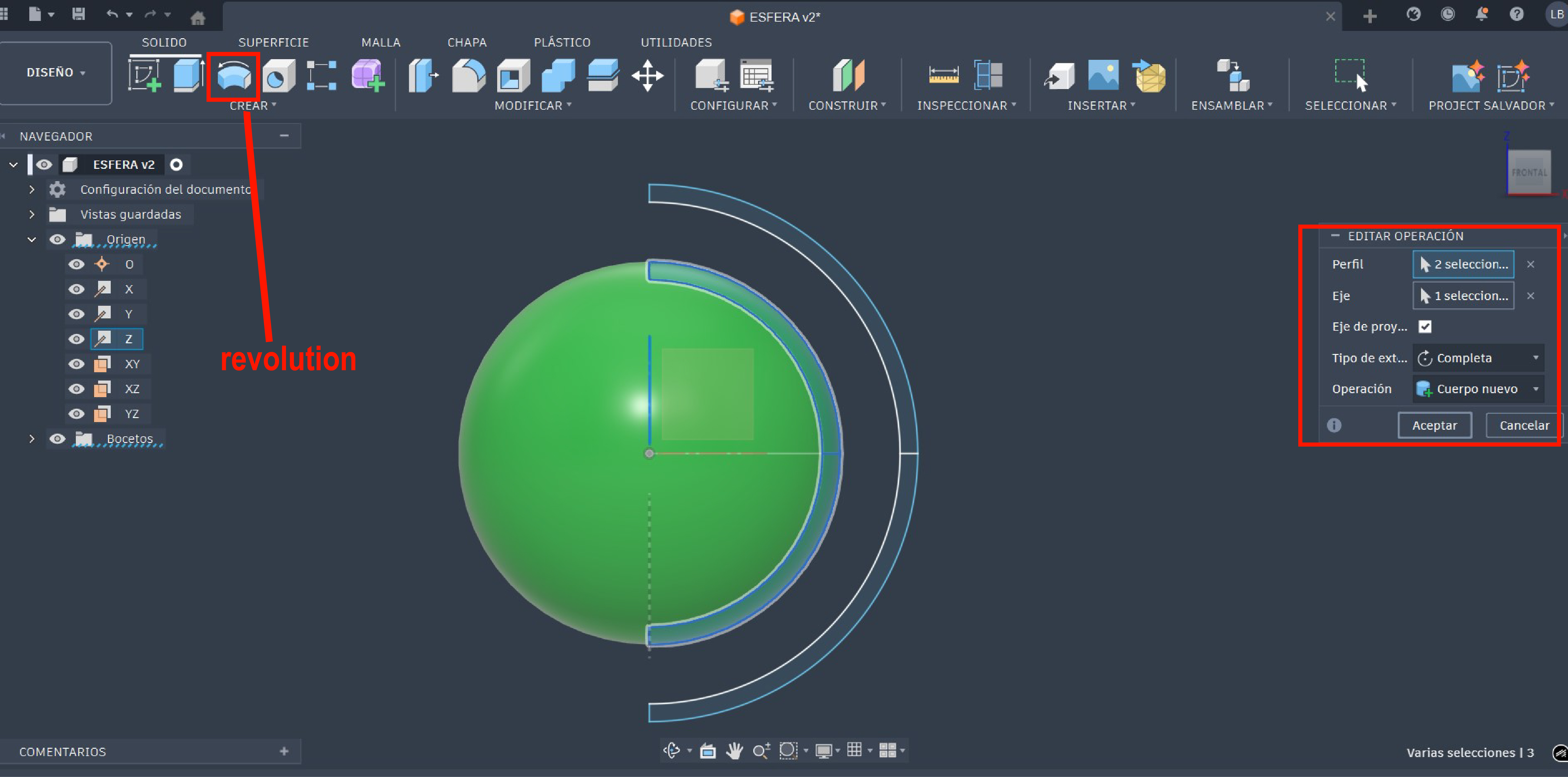
Subsequently, the revolve tool was applied to the outer profile using the same reference axis. This operation completed the hollow sphere geometry.
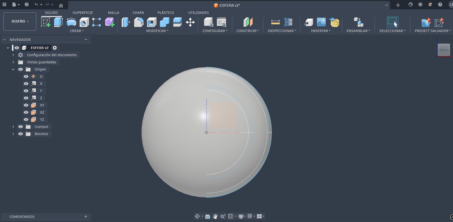
With both revolve operations completed, the model obtained its base three-dimensional form, allowing the next steps to focus on adding geometric patterns and additional details to increase the overall complexity of the object.
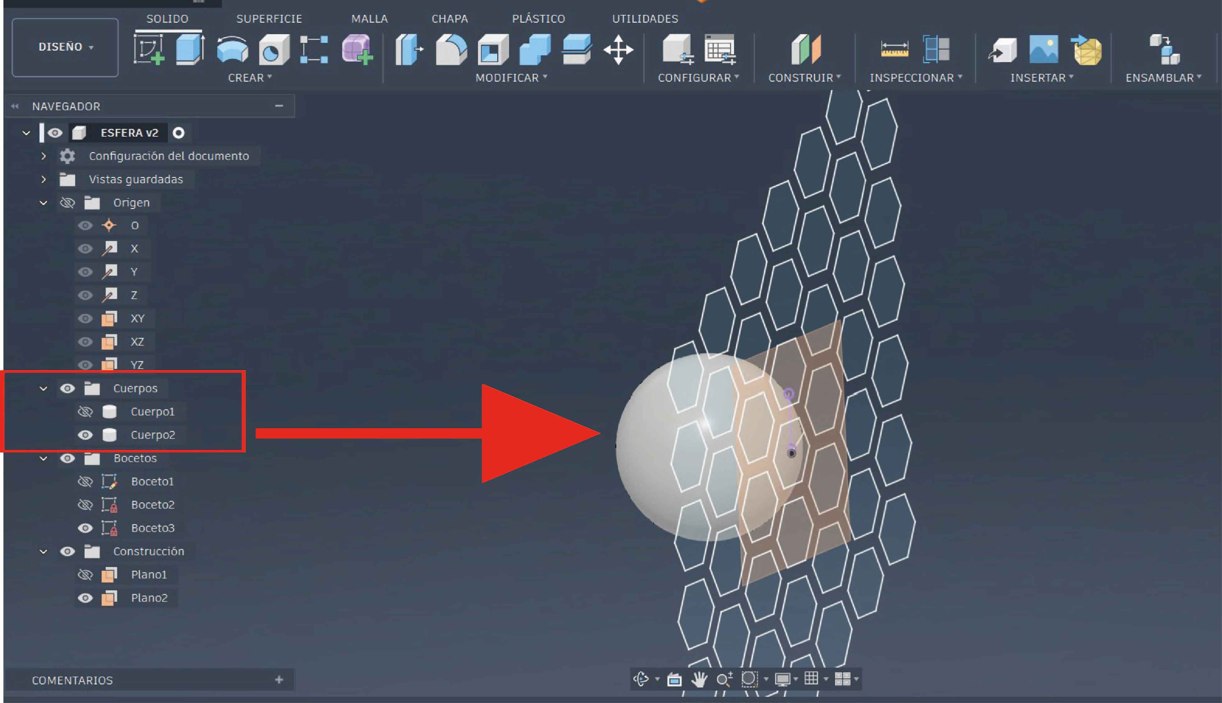
At this stage of the process, the model consists of two spheres, one contained inside the other. The next step was to apply a geometric pattern to the inner sphere.
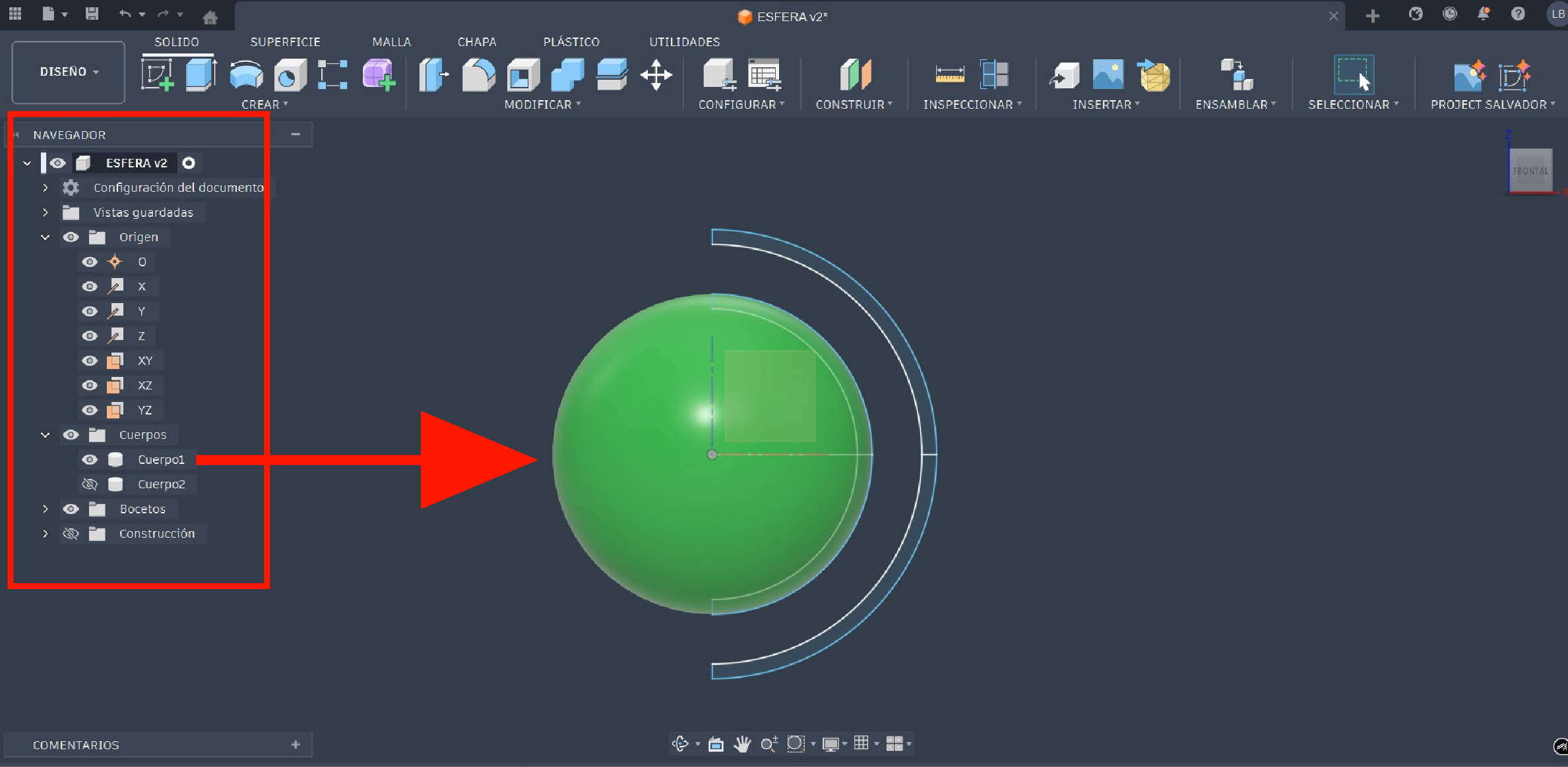
To create this pattern, it was necessary to temporarily hide the outer sphere and work only on the inner one. This was done through the navigation panel, under the Bodies section, where the visibility of the bodies can be managed by turning off the outer sphere.
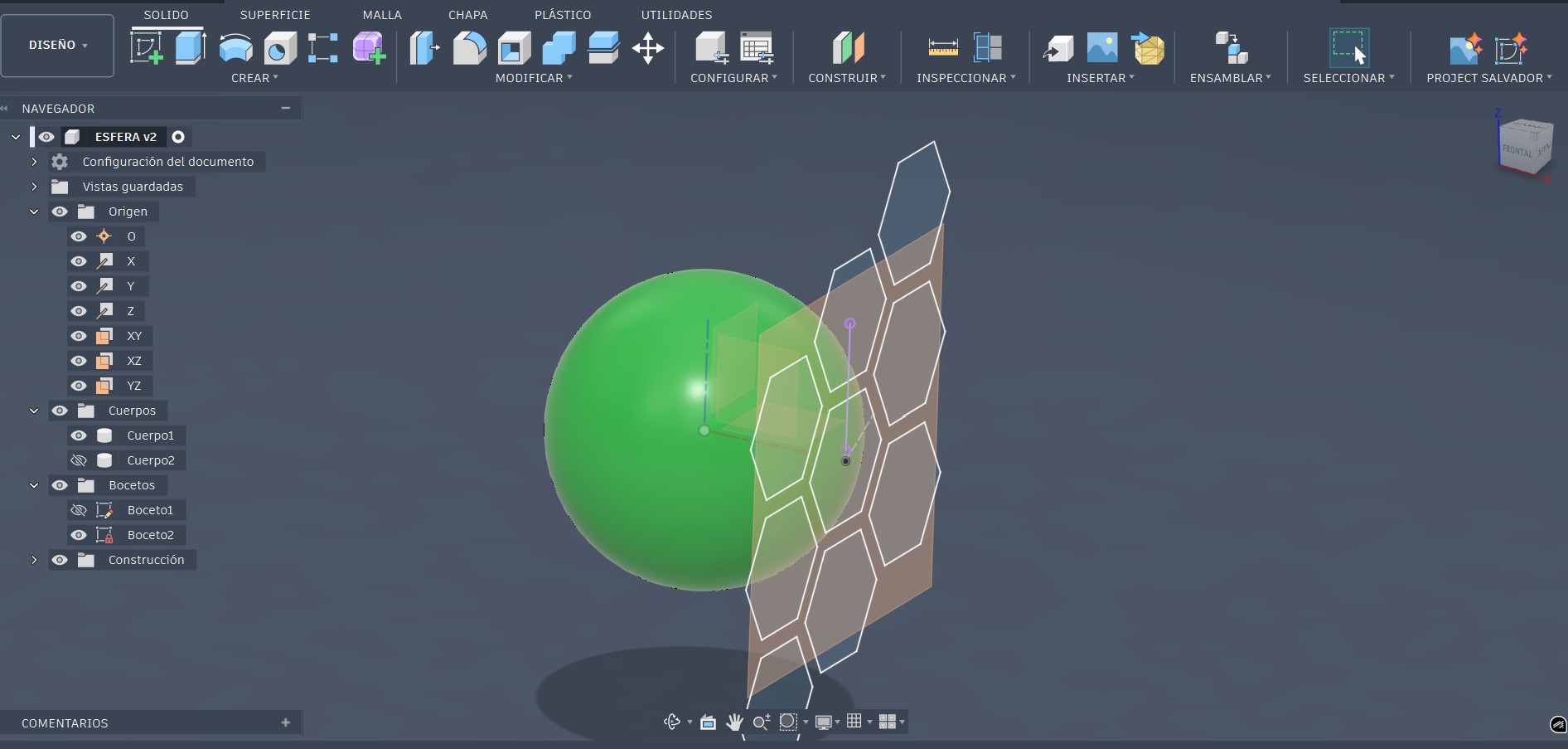
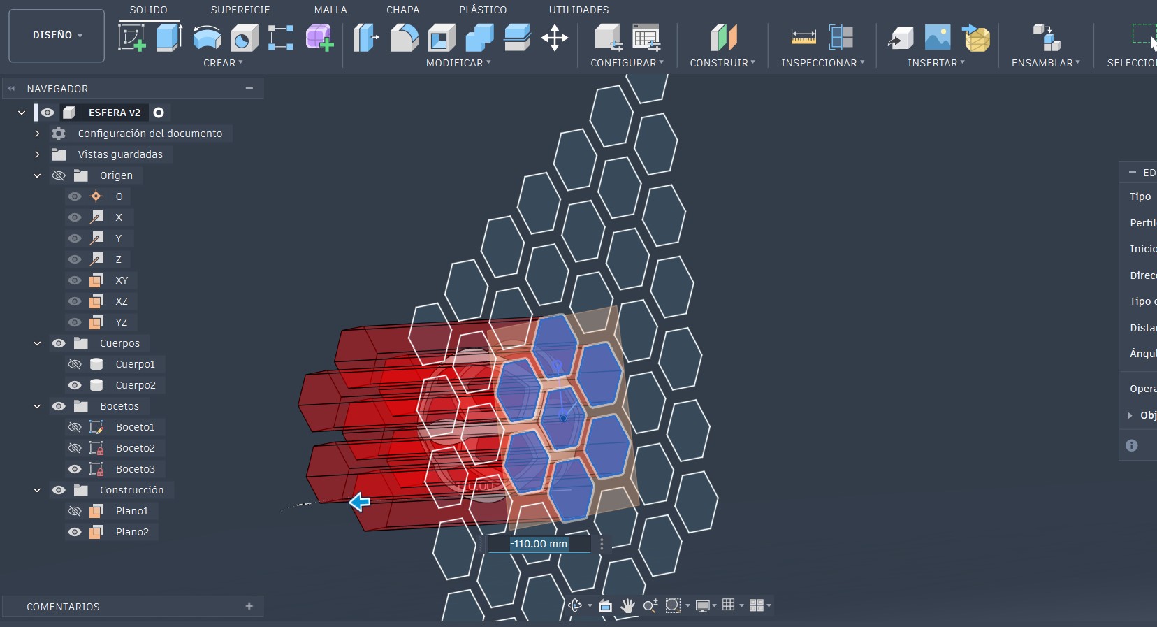
At this stage, it is possible to start creating the pattern. To do so, a construction plane tangent to the surface of the inner sphere was created. On this plane, the geometric pattern that would later be applied to the sphere was drawn.
Next, the profiles of the pattern were selected and, using the extrude tool in cut mode, the pattern was extruded through the entire part, as shown in the following image.
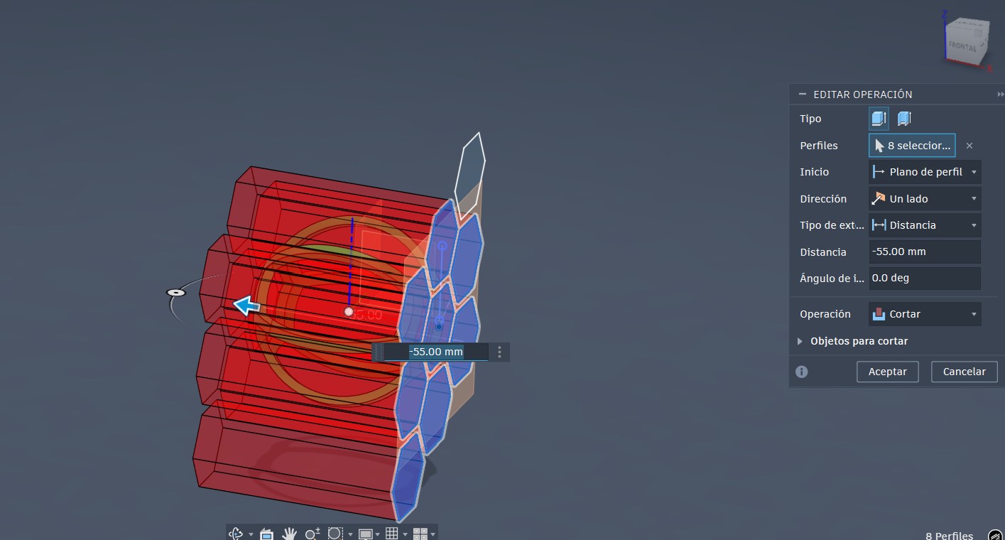
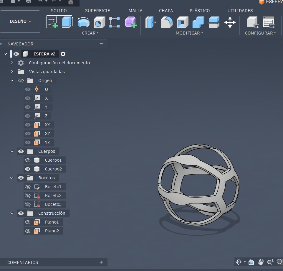
result
Once this stage was reached, the same process was repeated on the outer sphere. Through the navigation panel, under the Bodies section, the visibility of the bodies was managed by showing only the outer sphere and hiding the inner sphere.
This ensured that when the pattern was applied, the inner sphere was not affected by the operation.
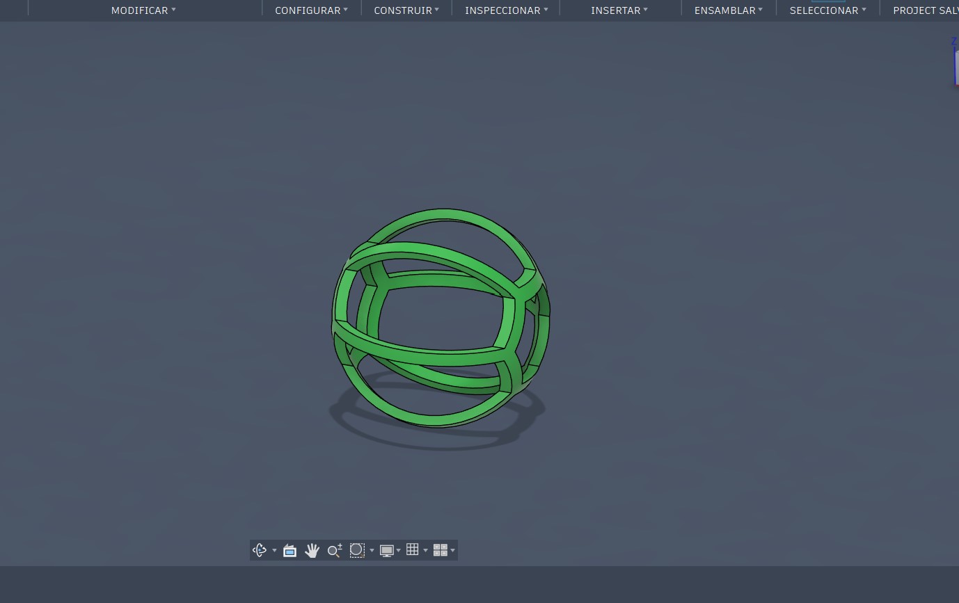
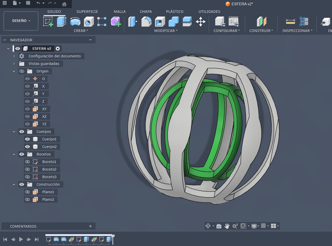
result
Once the pattern was applied to the outer sphere, the visibility of the inner sphere was re-enabled. As a result, the final desired design was obtained, as shown in the image below.
Disign final
Why this design is difficult to manufacture using subtractive methods
In subtractive manufacturing, the fabrication of this object is unfeasible due to the presence of closed internal geometries and encapsulated volumes. In this design, the inner sphere is completely contained within the outer sphere and cannot be produced from a solid block without dividing the part into multiple components.
Additive manufacturing allows this type of geometry to be fabricated by building the object layer by layer, making it possible to integrate complex internal volumes into a single piece without the need for assembly.
It can be observed that the design shows the inner sphere apparently suspended in mid-air; however, in 3D printing, slicing software allows the generation of support structures to ensure proper fabrication.
Process of printed 3D
Once the 3D modeling process was completed, the design was exported in STL format.
For the 3D printing of the object, two additive manufacturing technologies I experimented. The first was FDM (Fused Deposition Modeling), a technology that works by extruding molten plastic filament through a heated nozzle, depositing the material layer by layer to form the final object.
The second technology used was SLA (Stereolithography), a 3D printing process that uses an ultraviolet laser to cure liquid photosensitive resin, solidifying it layer by layer.
Additive Manufacturing Using FDM
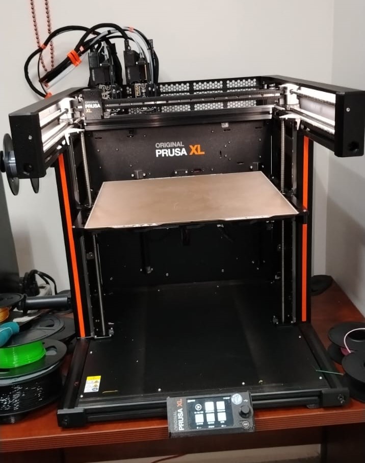
For the fabrication of the object using FDM technology, a Prusa XL dual-extruder 3D printer was used together with the PrusaSlicer slicing software.
Prusa XL
PrusaSlicer
Once the design was completed and exported in STL format, the next step was to perform the slicing process. This process consists of dividing the object into layers using slicing software, which generates the necessary instructions for 3D printing. In this case, PrusaSlicer was used.
-
The first step is to open the slicing software and load the 3D model file.
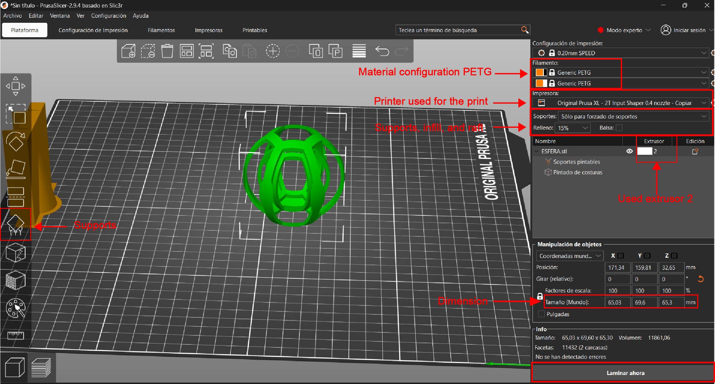
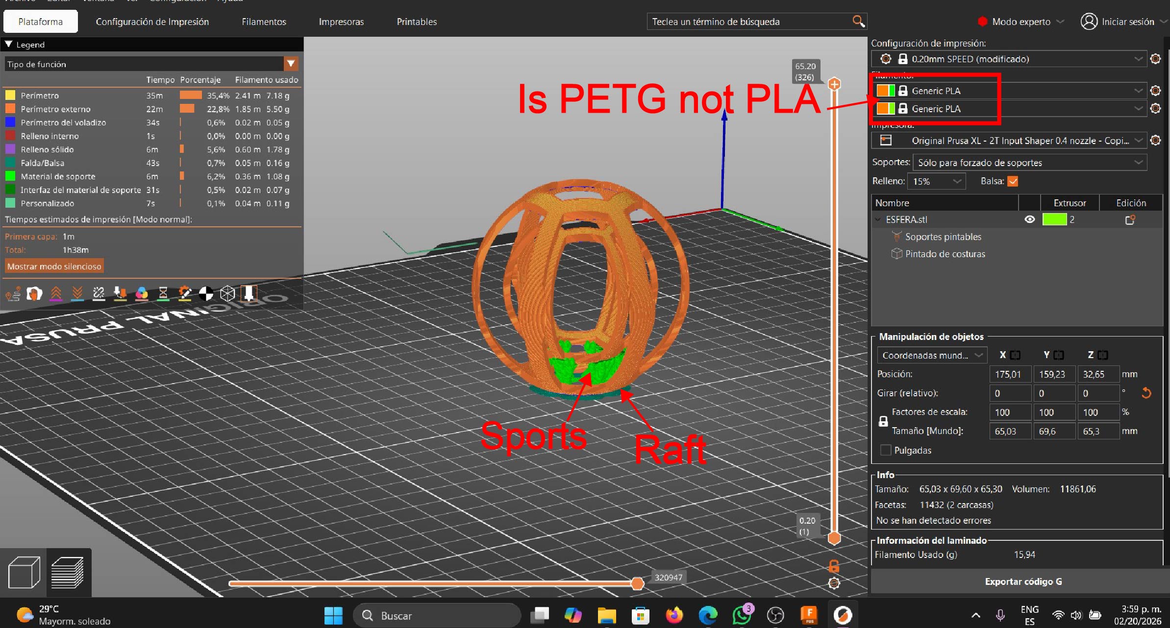
The image shows the PrusaSlicer interface, where I prepare my model for 3D printing on the Prusa XL printer. In this stage, I configure the printing parameters and select PETG as the material, since it offers higher strength and better durability compared to PLA.
I also configure enforced supports, which allows me to manually control where supports are generated, ensuring they are only placed where necessary due to the complexity of the geometry. Additionally, I enable a raft to improve bed adhesion during the printing process, even though it is not visible as active in the image.
-
setting soports
The 3D model we designed includes an internal sphere that is suspended in mid-air. In order to print it correctly, supports must be added, since 3D printing cannot be performed in the air. These supports are generated using the support tool in the PrusaSlicer software.
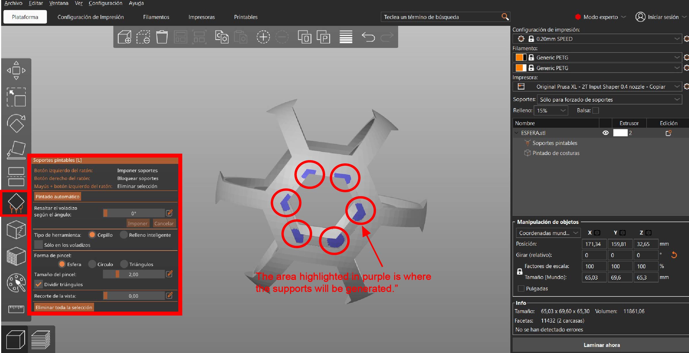
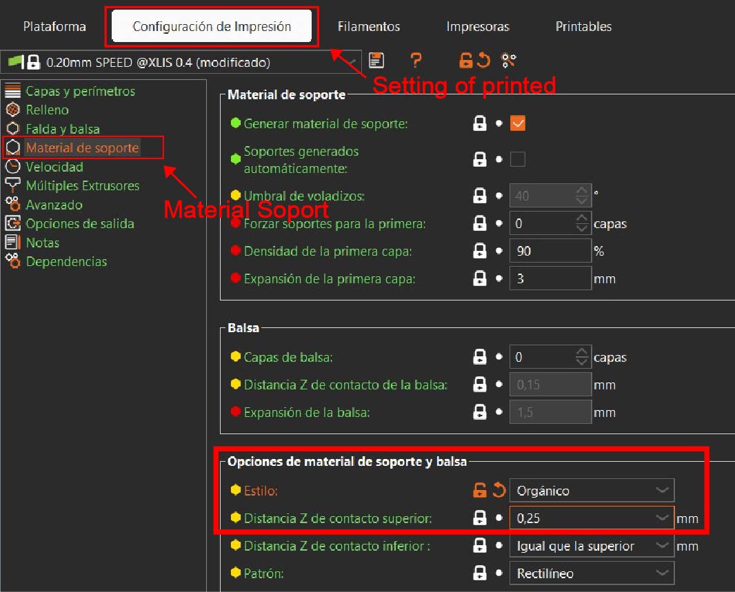
We configure the support style as organic and adjust the top contact Z distance to 0.25 mm in order to prevent the supports from sticking to the part, making them easier to remove after printing.
-
setting layers and wall
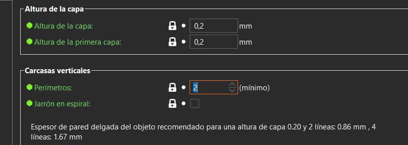
Once the supports were configured, I adjusted the perimeters and the layer height. The perimeters correspond to the walls of the object and are responsible for providing strength to the part.
The layer height defines the printing resolution, meaning the level of detail of the final object. The Prusa XL printer comes by default with a 0.4 mm nozzle, so I set the layer height to 50% of the nozzle diameter, resulting in a 0.2 mm layer height .
Finally, I configured 2 perimeters to increase the strength of the printed object
-
Setting of filament
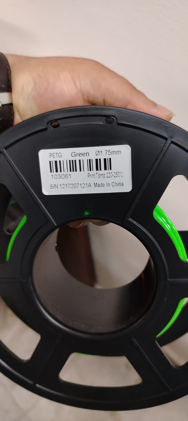
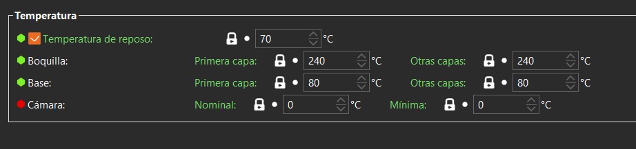
Once the perimeters, layer height, and supports were configured, the next step was to set up the material to be used. In this case, I used green PETG filament and set the following parameters:
- Nozzle temperature: 240 °C
- Bed temperature: 80 °C
Why these values?
The filament used has a melting range between 220 °C and 250 °C. Within this range, 240 °C provides stable extrusion and proper layer adhesion. The print bed temperature was set to 80 °C to ensure good first-layer adhesion and to reduce the risk of warping during the printing process.Filament used
Parameters used
Once these parameters were configured, I executed the slicing process, which generated a preview of the final print, allowing me to visualize the layers, supports, and material paths before starting the printing process.
evidence
Once the slicing process is completed, a .bgcode file is generated. This file can only be interpreted by the 3D printer being used, as it contains all the instructions required for the machine to execute the printing process, including movements, speeds, temperatures, and material deposition.
Once the .bgcode file was generated, it was transferred to the 3D printer using a USB flash drive. Subsequently, from the printer’s control panel, I selected the file and started the printing process.
The printer used for this print was the PRUSA XL, which automates key processes such as automatic bed leveling, a fundamental step to achieve good printing results. This system ensures precise bed leveling without manual intervention, significantly improving the quality of the first layer, which is critical in any 3D printing process. However, there are 3D printers such as the Ender 3 that do not include automatic leveling systems. In these cases, the bed must be leveled manually using a sheet of paper and adjusting the leveling screws located underneath the print bed. This is a repetitive process that requires several adjustments until proper leveling is achieved. In my case, I used the PRUSA XL because its automatic leveling system guarantees a properly leveled bed, resulting in a more reliable and consistent printing process
Subsequently, I proceeded with the 3D printing process. To do so, I went to the location where the printer is installed, powered on the machine, and then loaded the filament into the printer in preparation for printing.
loaded filament
Once the filament was loaded, I selected the .bgcode file from the printer’s control panel and started the print. During the first few minutes, I closely monitored the first layer, ensuring proper bed adhesion and that no issues occurred.
Throughout the process, the printer continued building the object layer by layer, following the instructions defined during the slicing stage.
Once the printing process was completed, I removed the part from the print bed and carefully removed the supports generated during slicing. The printed object correctly reproduces the designed geometry, including the internally suspended sphere, confirming that additive manufacturing is the appropriate technology to produce this type of complex geometry.
The final result demonstrates that 3D printing enables the fabrication of objects that would be extremely difficult or impossible to manufacture using subtractive manufacturing, especially when closed internal cavities and non-accessible features are involved.
This is how the final result of the FDM 3D print turned out 😊👌
This exercise demonstrates that 3D printing is not only a rapid prototyping tool but also a key technology for manufacturing objects that would be extremely difficult or impossible to produce using traditional manufacturing methods.
Additive Manufacturing Using LCD/SLA (Resin)
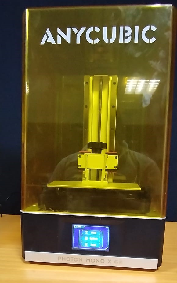
For the 3D printing of the object, I used the Anycubic Photon Mono X 6K printer together with the Photon Workshop slicing software, both developed by Anycubic.
Anycubic Photon Mono X 6K – Technical Specifications
| Feature | Specification |
|---|---|
| Printing Technology | SLA / LCD (photosensitive resin) |
| Screen | 6K monochrome LCD screen |
| Screen Resolution | 5760 × 3600 pixels |
| XY Resolution | ~34 µm |
| Layer Height (Z) | 0.01 – 0.15 mm |
| Build Volume | 245 × 197 × 122 mm |
| Light Source | 405 nm UV light |
| Printing Speed | Up to 80 mm/h |
| Compatible Materials | UV photosensitive resins |
| User Interface | Touch screen |
| Connectivity | USB |
| Slicing Software | Photon Workshop |
| Typical Applications | High-precision and high-detail parts |
Anycubic Photon Mono X 6K
Anycubic Photon Workshop
Preparing the object for 3D printing
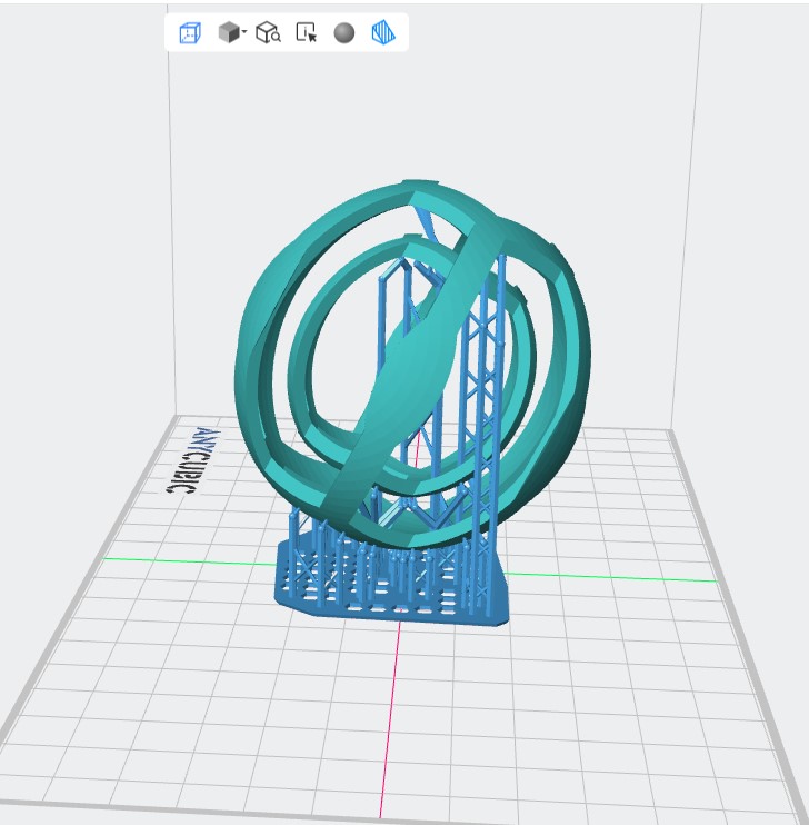
We open the slicing software and import the 3D model into the workspace.
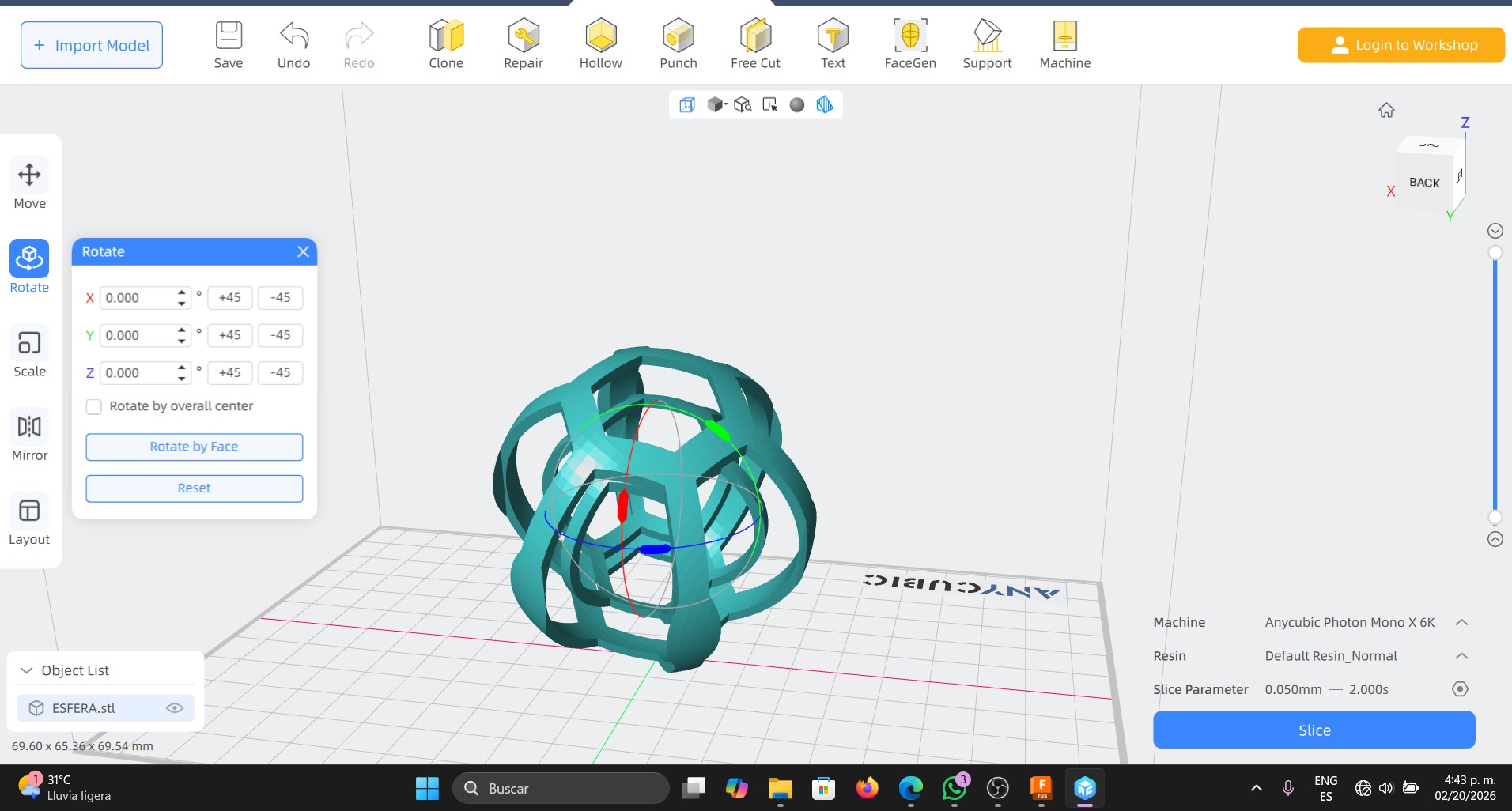
Once the 3D model is imported into the slicing software, the next step is to orient the object within the build volume. Orientation is a crucial step, as it helps reduce the number of supports, improves surface quality, and ensures a successful print.
After that, supports are generated, which are required to hold the parts of the model that remain suspended during the resin printing process. These supports prevent deformations and structural failures while printing.
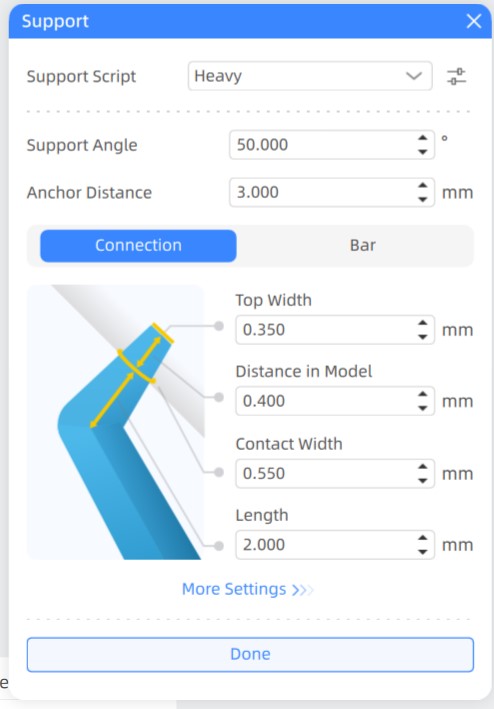
Support Parameters Configuration used
| Parameter | Value | Description |
|---|---|---|
| Support Script | Heavy | Defines the type of support used. Heavy supports are stronger and more stable, ideal for large overhangs or suspended parts. |
| Support Angle | 50° | Sets the minimum angle at which supports are generated. Surfaces exceeding this angle will receive supports to avoid printing in mid-air. |
| Anchor Distance | 3.000 mm | Determines the distance between support anchor points. A value of 3 mm provides a good balance between stability and easy removal. |
| Top Width | 0.350 mm | Specifies the diameter of the support tip that contacts the model. Smaller values reduce visible marks on the surface. |
| Distance in Model | 0.400 mm | Indicates how deeply the support penetrates into the model, ensuring a firm connection without damaging the geometry. |
| Contact Width | 0.550 mm | Defines the width of the contact point between the support and the model, improving adhesion during printing. |
| Length | 2.000 mm | Sets the length of the final segment of the support near the model, allowing flexibility and stress absorption during printing. |
Resin Parameters Configuration
Once the model and supports were defined, I configured the resin parameters in the Anycubic Photon Workshop slicing software. These parameters control how the liquid resin cures layer by layer during the SLA printing process.
| Parameter | Value | Description |
|---|---|---|
| Layer Thickness | 0.05 mm | Defines the layer height, balancing print quality and printing time. |
| Normal Exposure Time | 2.0 s | Time used to cure each standard layer of resin. |
| Off Time | 0.5 s | Allows resin to flow and settle before the next exposure. |
| Bottom Exposure Time | 23.0 s | Ensures strong adhesion of the first layers to the build plate. |
| Bottom Layers | 6 | Number of initial layers printed with longer exposure. |
| Z Lift Distance | 8.0 mm | Distance the platform lifts to detach each cured layer from the FEP. |
| Z Lift Speed | 2.0 mm/s | Speed at which the platform moves up after curing a layer. |
| Z Retract Speed | 3.0 mm/s | Speed at which the platform returns to the printing position. |
| Anti-aliasing | Enabled (Level 1) | Improves surface smoothness and reduces layer stepping. |
Once the supports and parameters of resin are properly configured, I execute the slicing process to convert the 3D model into printable layers.
After the slicing process, the software displays a preview of all the generated layers. Each layer is projected onto the LCD screen, where the light cures the resin in specific areas, gradually forming the printed object.
This process generates a .pwmb file, which is the file that is transferred to the printer.
Next, the printing process begins. From the printer’s control panel, I selected the generated file and started the print job.
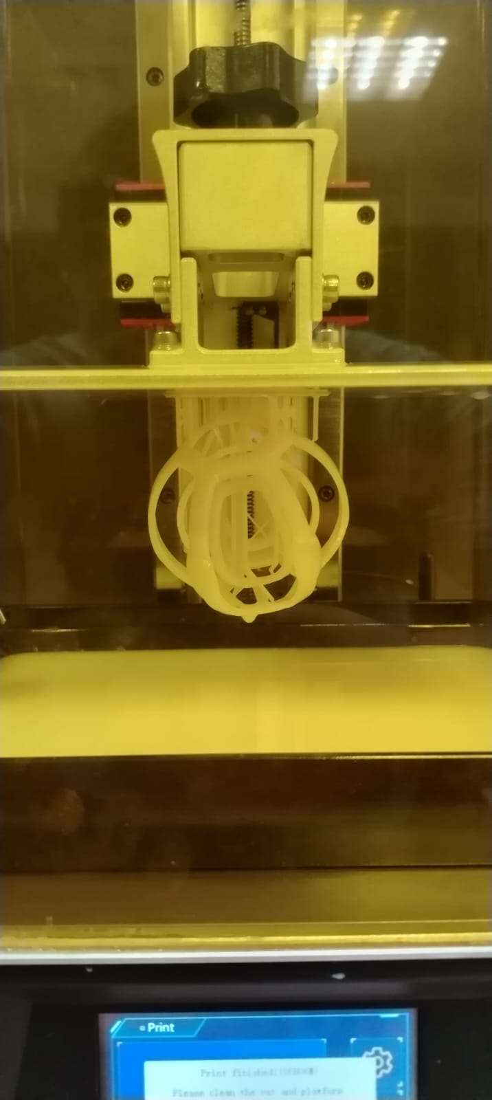
Once the printing process was completed, I moved on to the next step, which is washing and curing the printed part. For this process, I used 95% denatured alcohol, tweezers to remove the supports, and a wash and cure machine. Additionally, protective gloves were used to avoid direct contact with the resin.
- The first step was to remove the build plate from the printer together with the printed part.
- The second step consisted of removing the part from the build plate using a plastic spatula.
- Next, the part was washed with 95% denatured alcohol. Once cleaned, the part was allowed to air-dry at ambient conditions. While the part was drying, the machine was cleaned.
- After the part was completely dry, the support structures were removed.
- As the final step, the part was placed in the UV curing machine.
This was the final result 😊👌
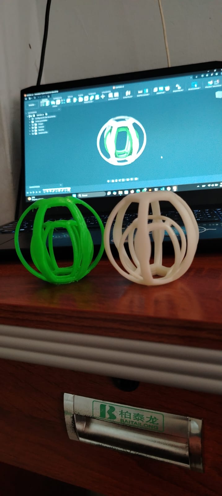
As a final result, two printed objects were obtained: one produced using FDM technology and the other using SLA technology. Both technologies present advantages and disadvantages.re un ultimo proceso de lavado y curado del objeto impreso
For example, in FDM printing, the green sphere shows visible layer lines, which significantly affects the resolution and level of detail of the printed object. In this case, the object does not contain complex or organic details, so this limitation does not greatly impact its functionality.
In contrast, resin-based printing (SLA) provides a smooth and even surface finish, with printing layers that are almost imperceptible. This allows for higher detail resolution and better overall surface quality.
FDM printing is ideal for rapid prototyping, as its printing process is simpler and cleaner. However, resin printing requires greater care during operation due to the handling of chemical materials that may pose health risks. In addition, this type of printing involves additional post-processing steps, such as washing and UV curing of the printed object.
Scanned of an object 3D
Scanner used: Revopoint POP2
Software: Revo Scan 5
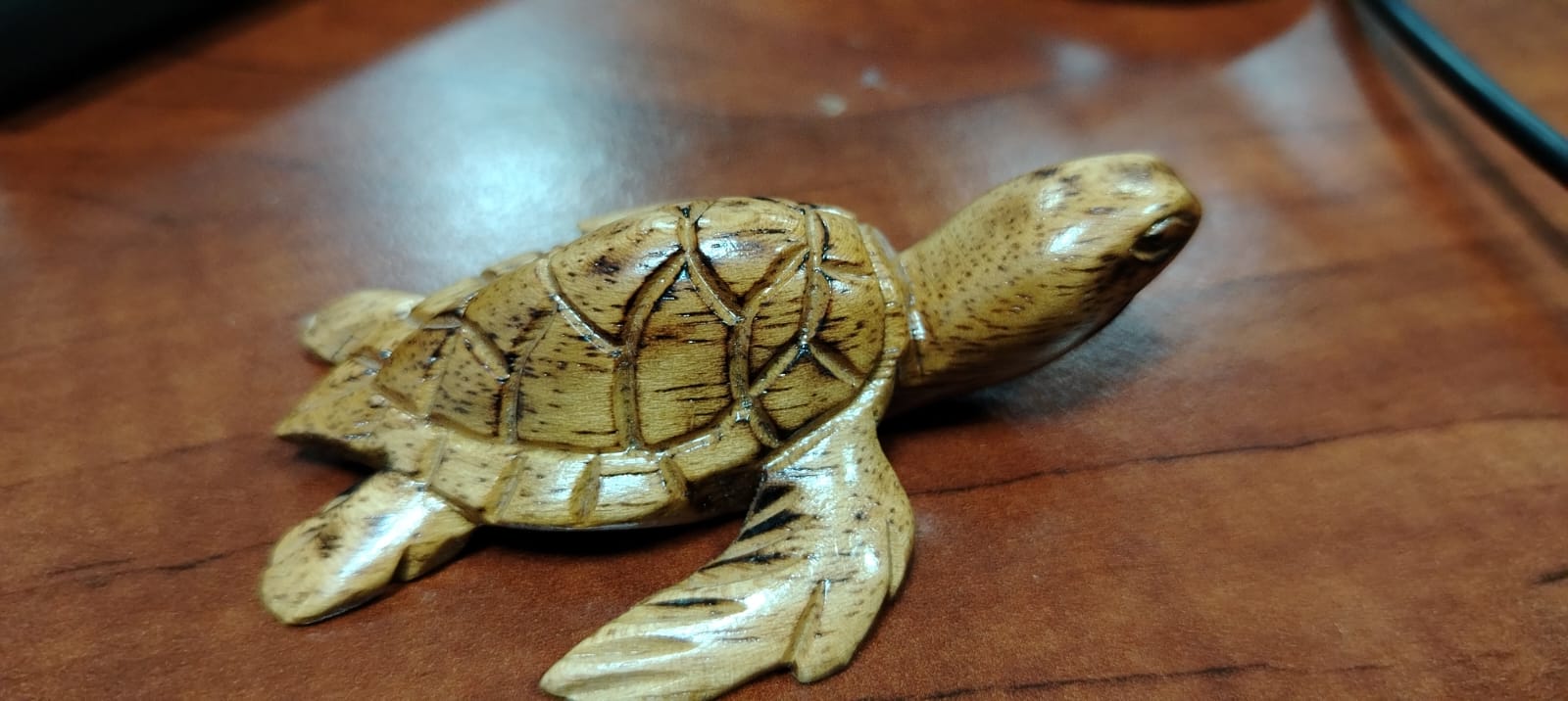
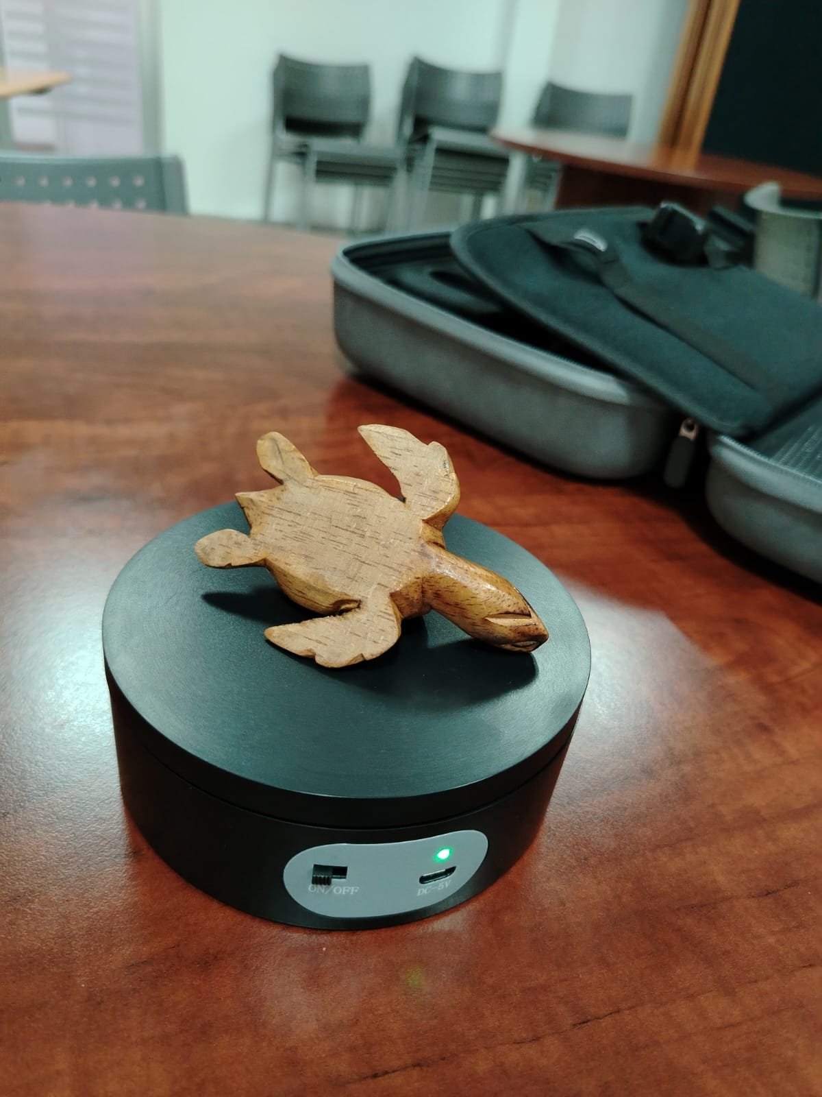
Object scanned: Carved wooden turtle
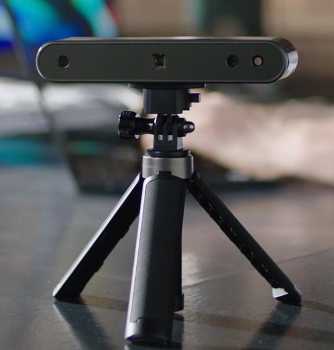
Revopoint POP2 – Overview
Definition:
The Revopoint POP2 is a portable 3D scanner based on structured light technology.
Its main function is to capture the three-dimensional shape of physical objects
and generate a digital 3D model that can be used for design, analysis, and 3D printing.
Step 1: Structured Light Projection
The POP2 projects a structured light pattern onto the surface of the object to be scanned. As the light pattern deforms according to the geometry of the object, the scanner’s cameras capture this deformation, which is later used to calculate depth and surface details.
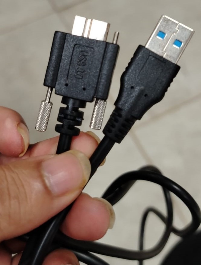
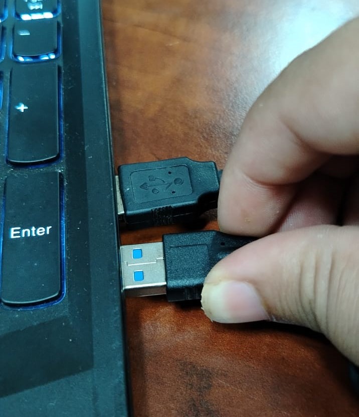
This scanner supports two types of communication: Wi-Fi and USB. For this project, the USB connection will be used.
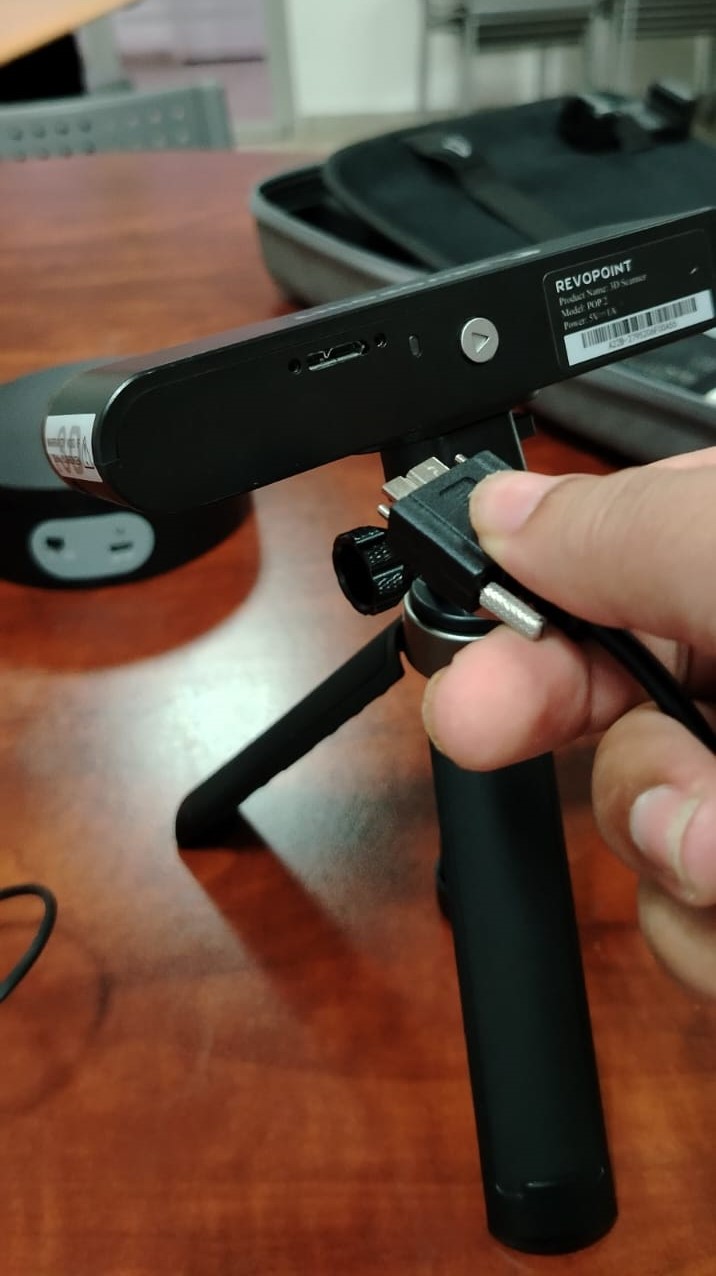
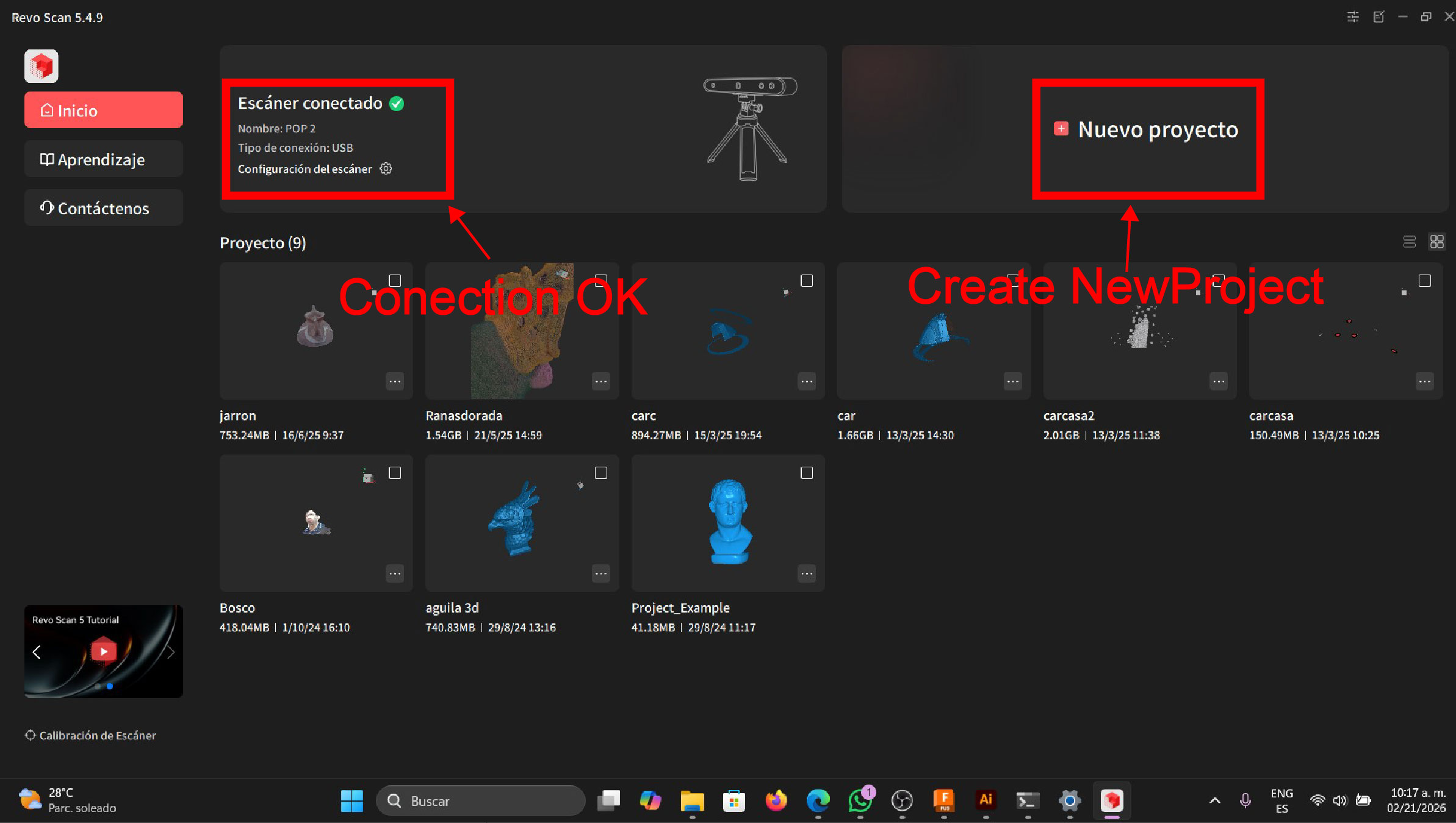
Once the scanner is connected to the computer, the Revo Scan 5 software is launched.
Comenzando con el escaneo 3D
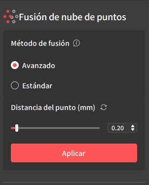
Once the scanning process is completed, the generated point cloud is merged. The point distance is set to 0.2 mm; the smaller the distance, the longer the point cloud processing time. An advanced fusion method is selected to achieve better accuracy and surface quality
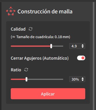
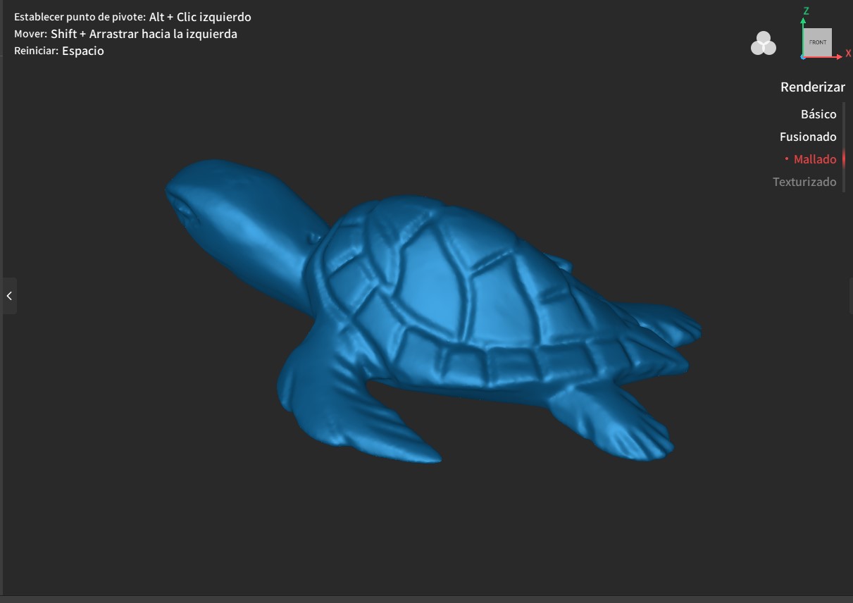
Using the mesh reconstruction tool, the point cloud is converted into a 3D mesh
Result 1
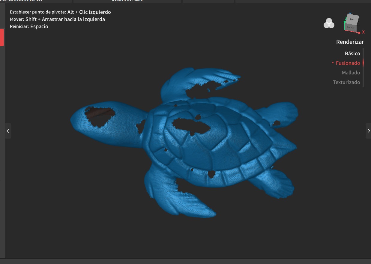
As observed, the model contains holes; however, by using the hole-closing tool and performing a second scan of the object, satisfactory results can be obtained
he object was scanned from the bottom by rotating the turtle and performing an additional scan.
Result 2
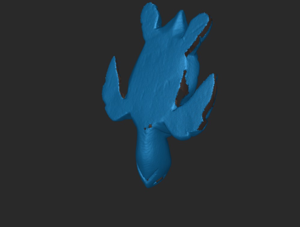
Although the object still presents holes, the hole-closing tool is applied at this stage to correct the mesh.
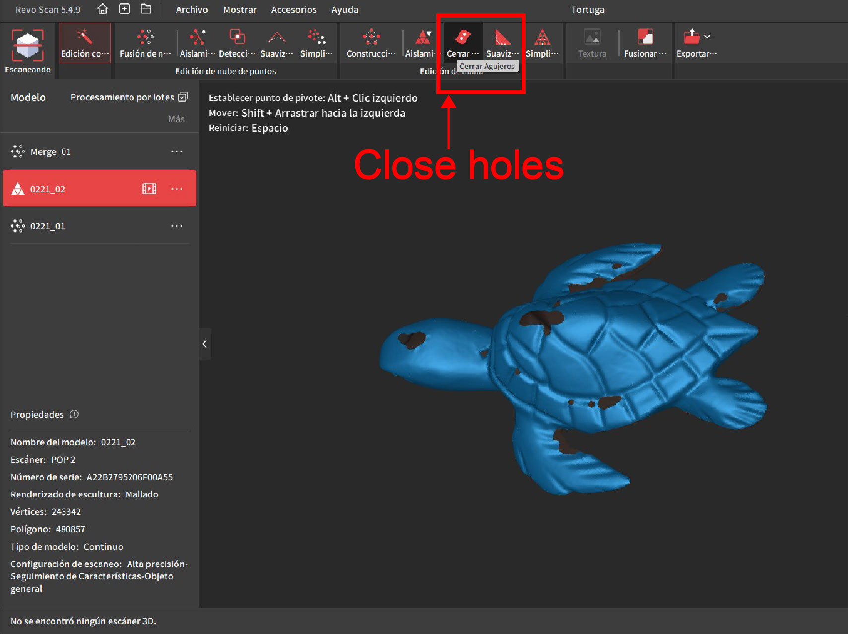
Result Final
It is observed that the model is fully sealed and ready for 3D printing