Group assignment
Objective
-
Compare as many tool options as possible.
-
Document your work on the group work page and reflect on your individual page what you learned.
Here I share the link to my group assignment.
Indivual assignment
- Write an application for the embedded board that you made. that interfaces a user with an input and/or output device(s)
This week focuses on developing a graphical user interface that allows interaction with the PCB board previously designed and fabricated in week 7. For this task, tools such as Qt Designer, Arduino IDE, and Visual Studio Code will be used.
To download Qt Designer, you can visit the following link.
Qt Designer is a tool that allows users to create graphical interfaces visually by dragging and dropping widgets. This approach significantly reduces development time compared to building interfaces entirely through code. In my case, this was my first time using it.
Once downloaded, proceed with a standard Windows installation.
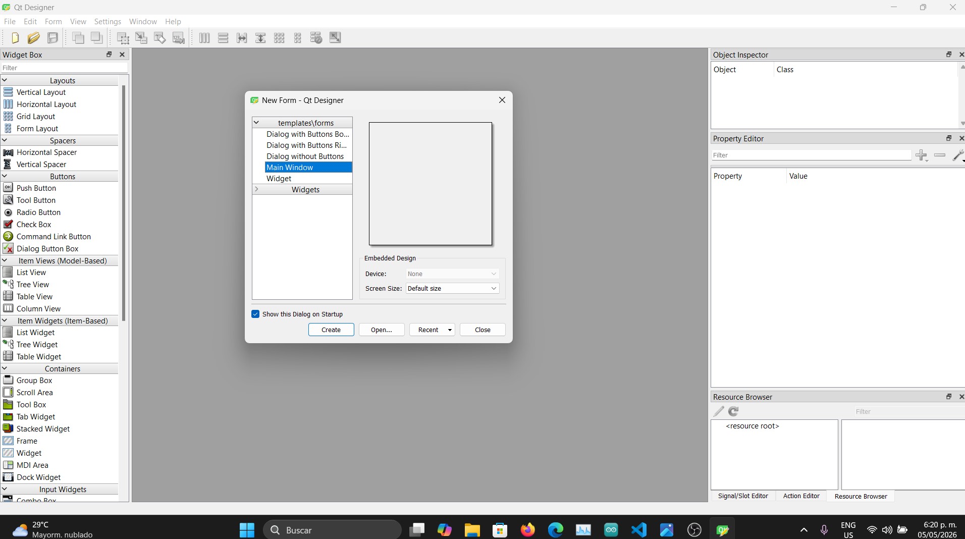
After launching the program, an initial window appears where you must select the MainWindow option and then click the Create button, as shown in the following image.
A workspace (canvas) will then open, which is where the interface of the application will be designed.
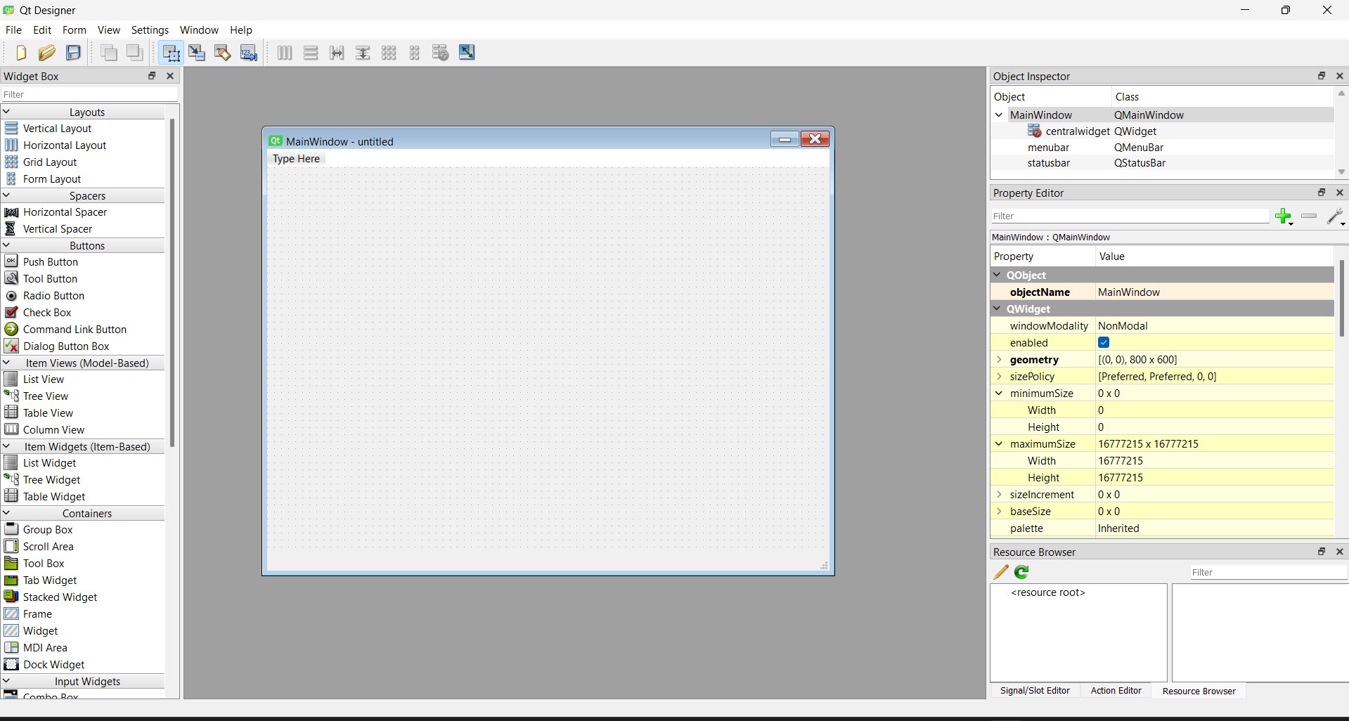
On the left side, you will find the Widget Box, which contains all available interface elements. On the right side, you can see the properties panel, where you can modify attributes such as name, size, font, and more. The central area is the main design workspace where all components are placed.
At this point, creativity and the specific requirements of your application will guide the design process.
In my case, I decided to build an interface to control the ON and OFF state of an output device. Below is the sequence of steps I followed to achieve this.
-
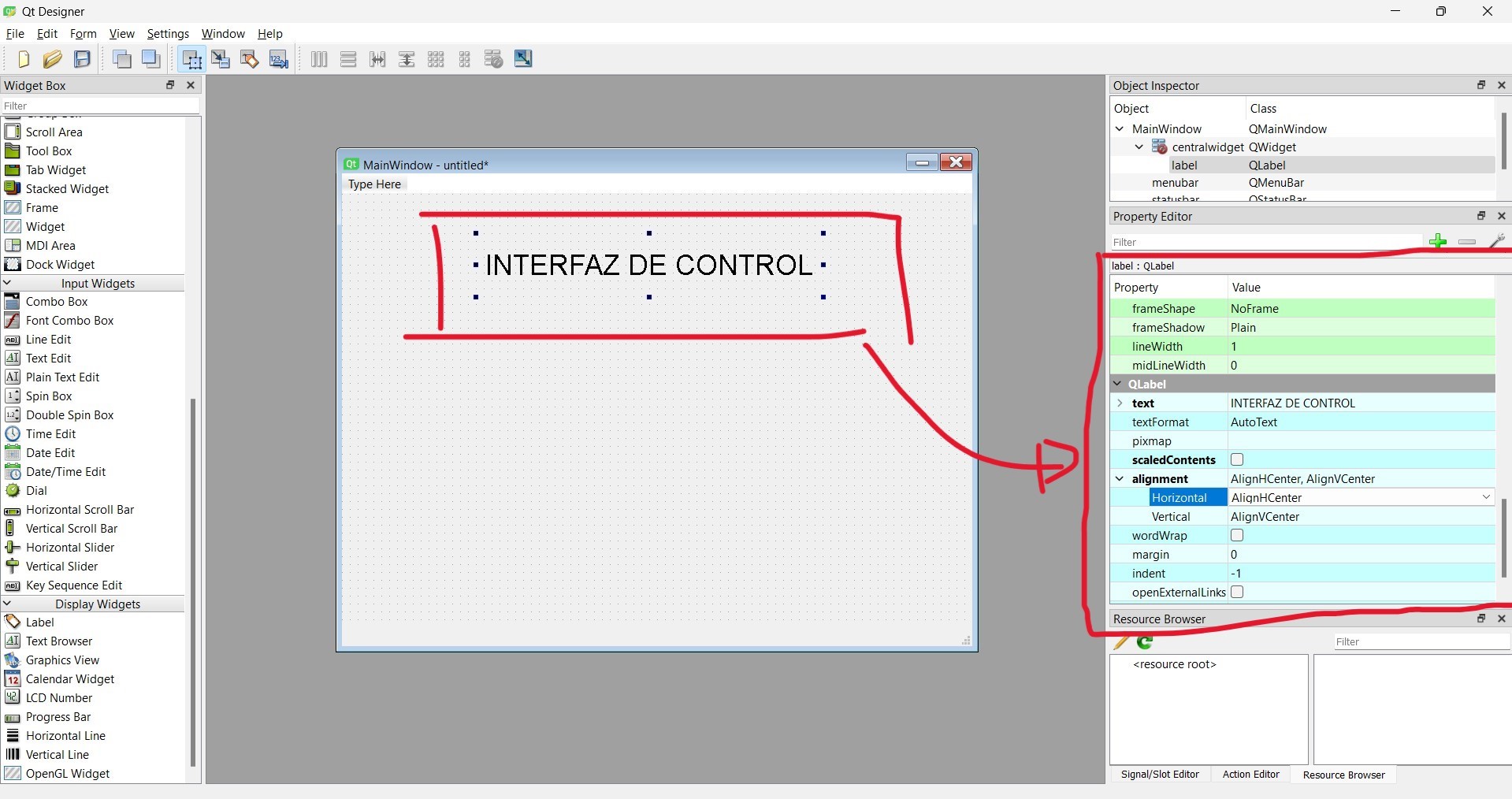
After creating a new project, the first step was to add a Label widget to display the title of the interface.

Then, I adjusted its size and modified properties such as name, font, and style, resulting in the following configuration.
-
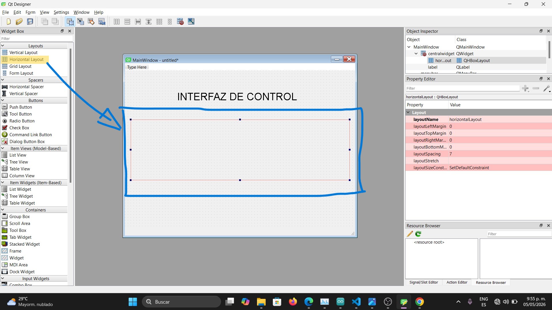
The next step was to add a Horizontal Layout.
-
Then, I added two buttons inside the layout. These buttons are used to turn the output device ON and OFF.
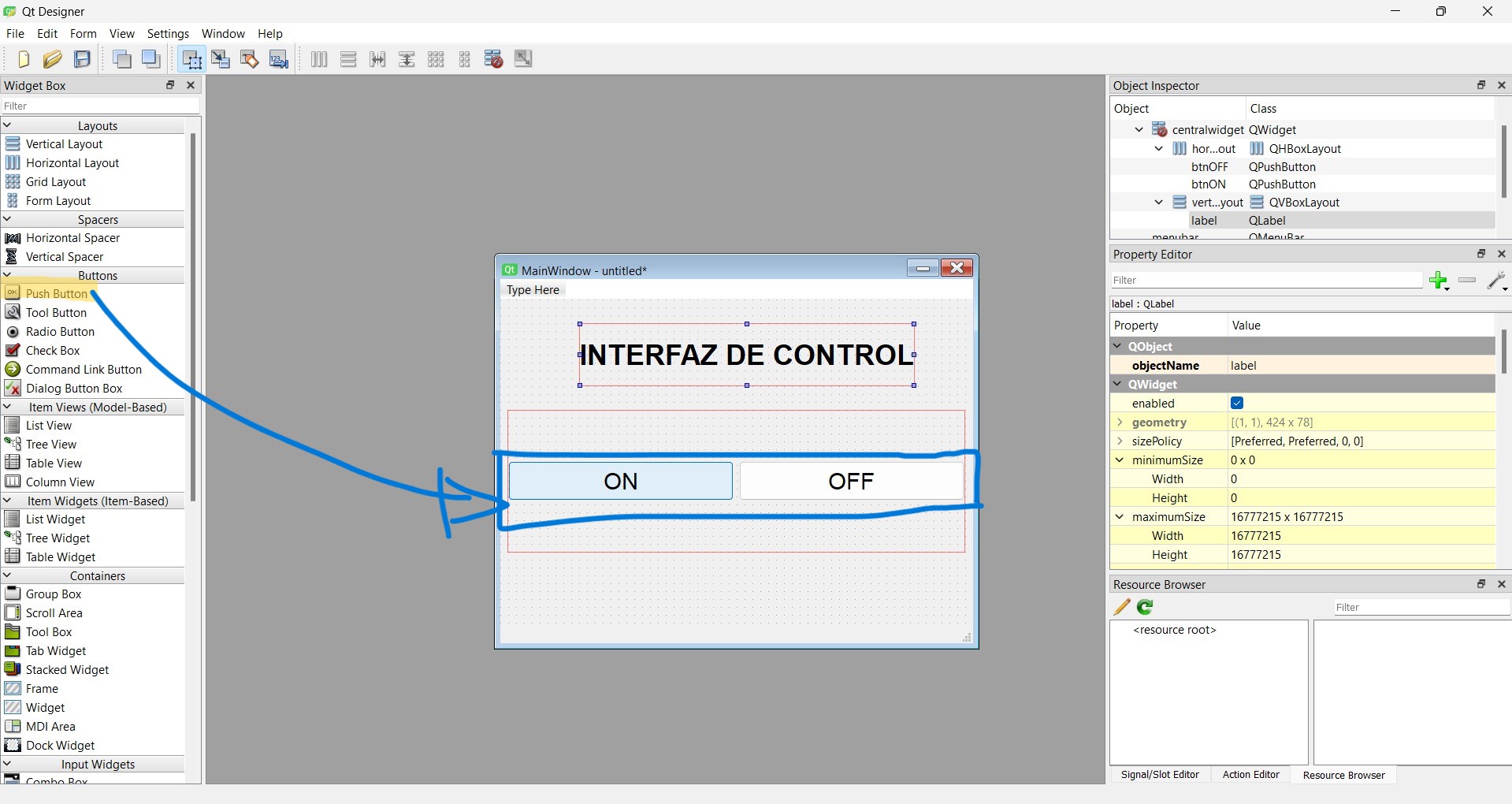
Similar to the label, I modified their properties such as size, font, and object names. One was named
btnOFFand the otherbtnON. -
Next, I added another Label to display the device status. This label informs the user whether the device is ON or OFF. I renamed it to
labelEstadoand applied similar styling as the main title.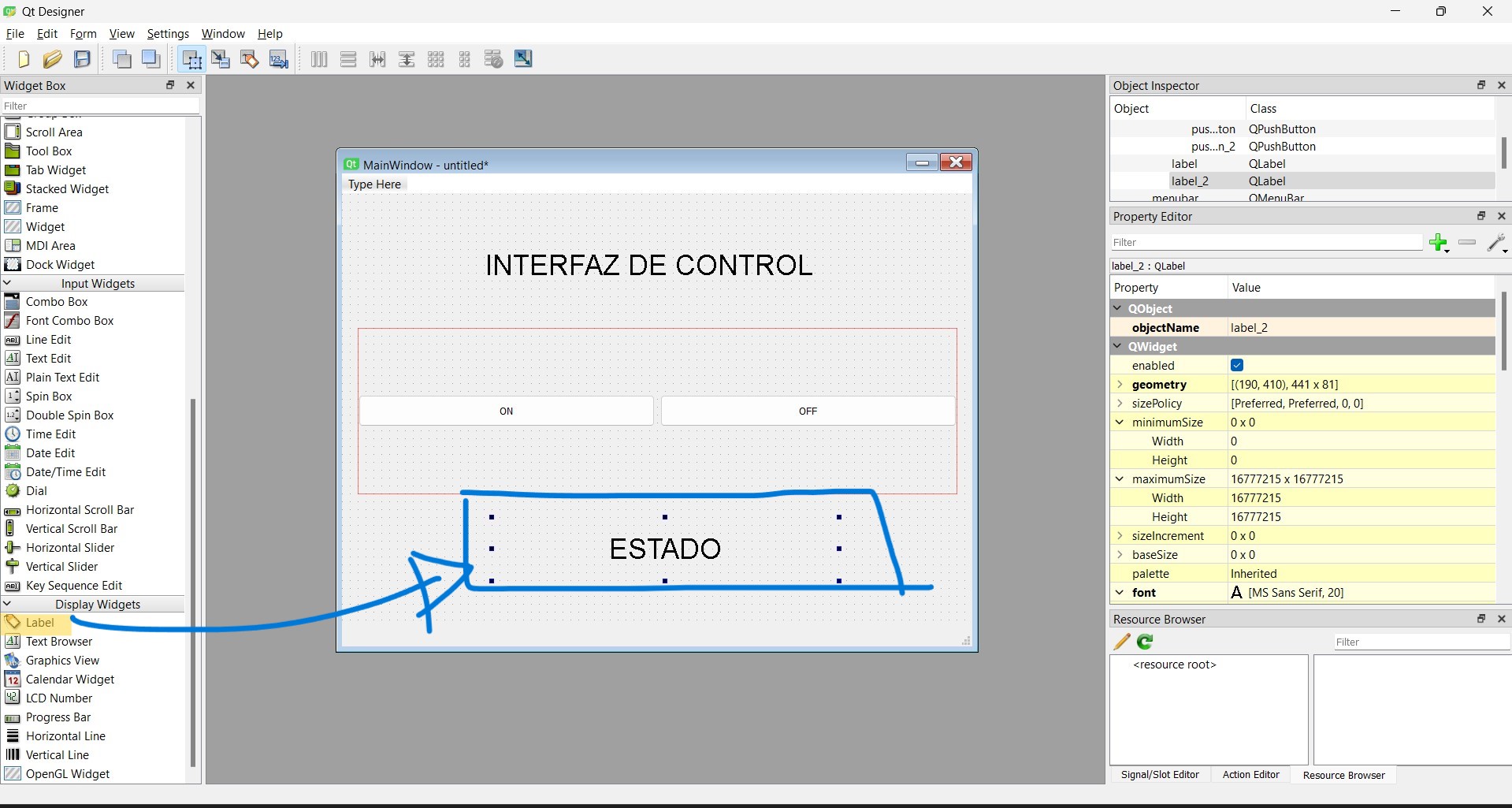
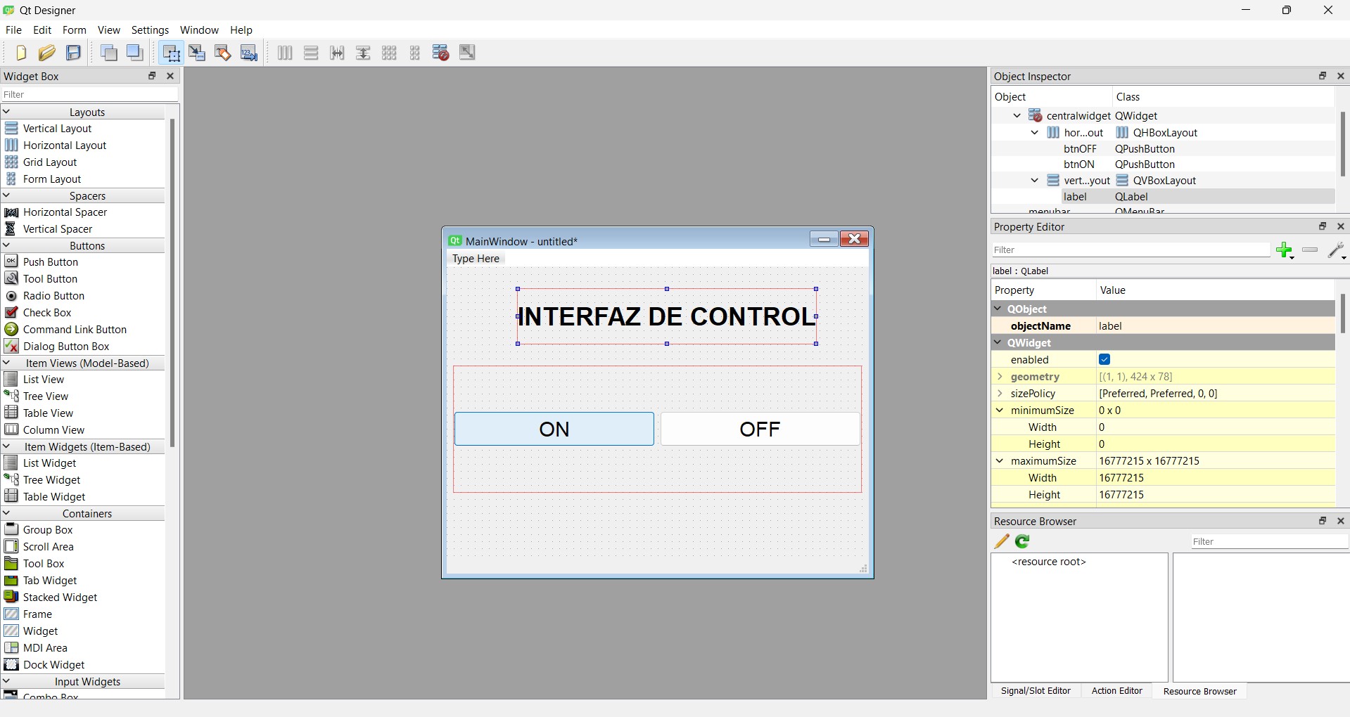
At this stage, the interface looked like this:
-
To improve the visual appearance, I applied custom styles to the interface. First, I changed the background color by right-clicking on the main window and selecting "Change Style Sheet".
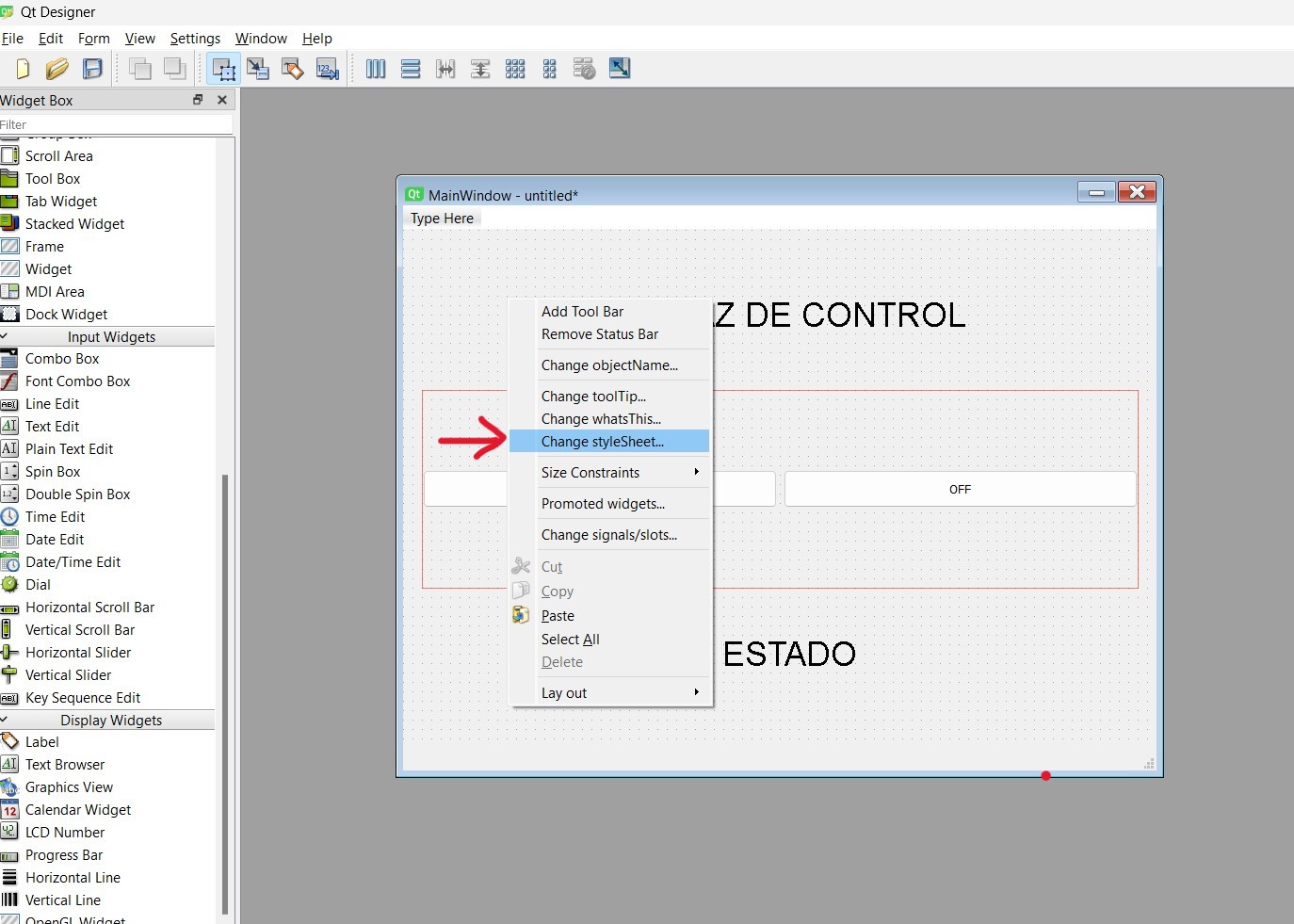
This opens a window where CSS-like styles can be applied to the interface.
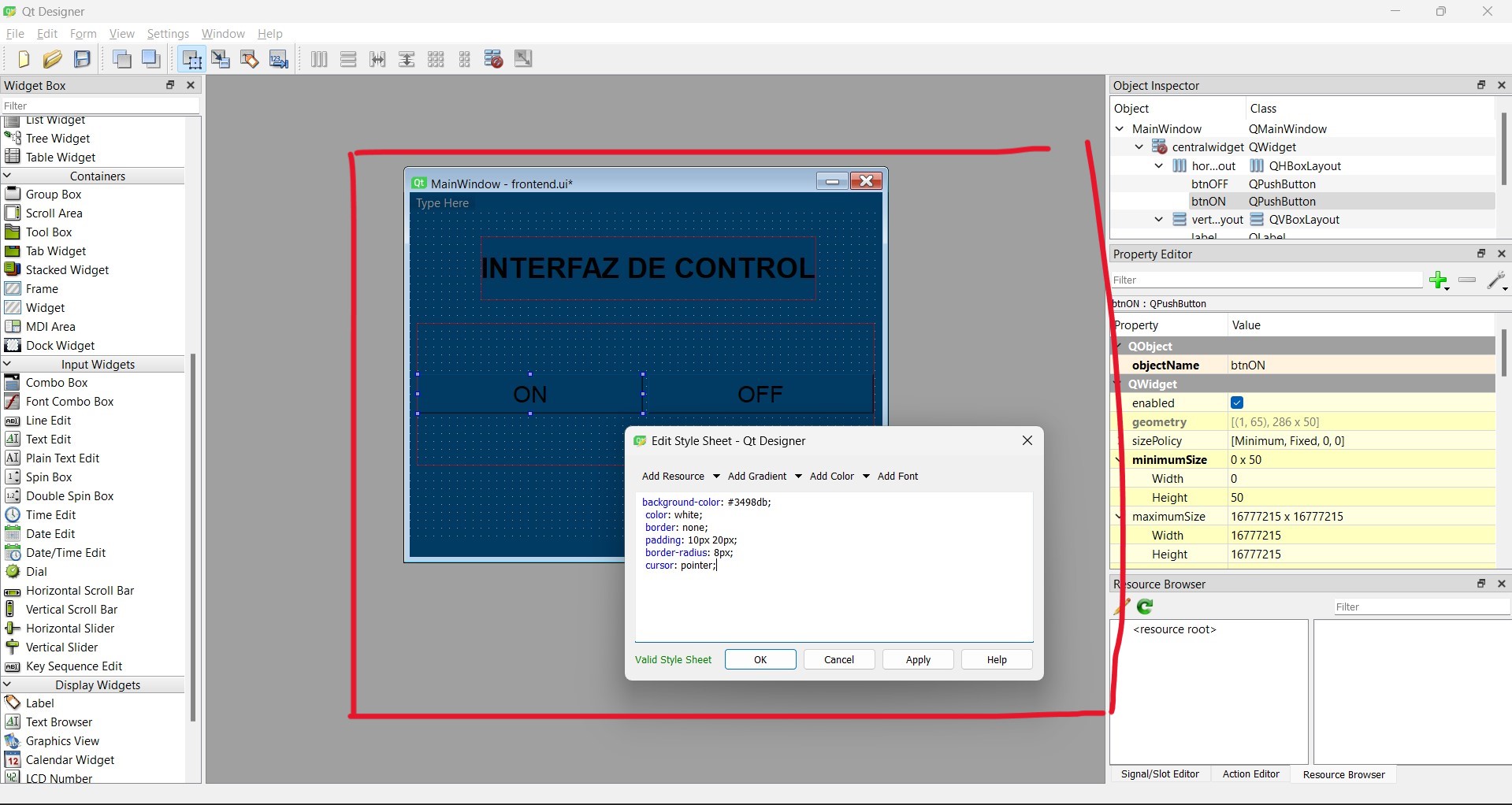
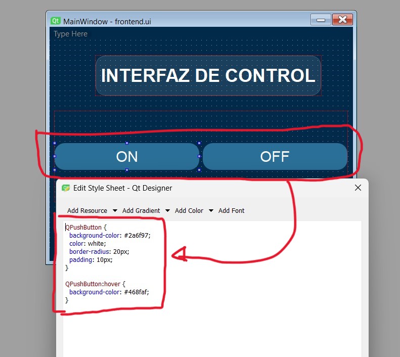
I repeated the same process for buttons and labels to achieve a consistent visual design.
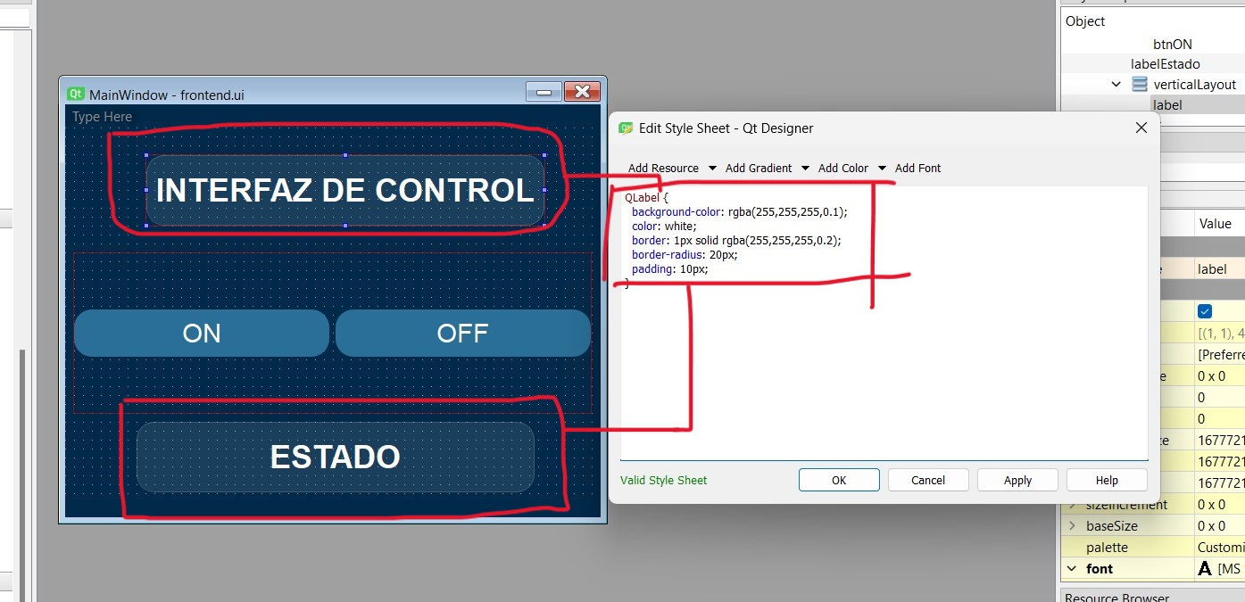
Label style:
-
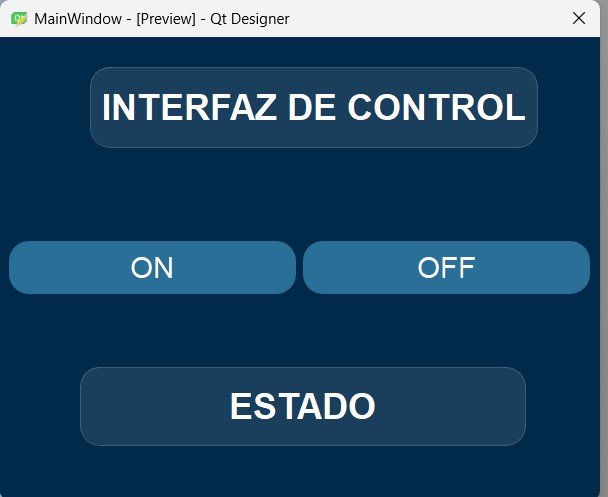
Finally, the interface looks as follows:
-
Once the interface is completed, it is saved as frontendCode.ui. This file is an XML-based design file and must be converted into a Python file (e.g., frontendCode.py) in order to add functionality.
To perform this conversion, the PyQt6 package must be installed.
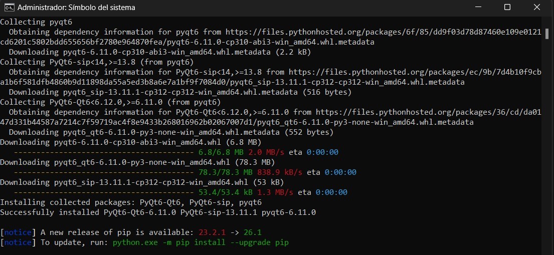
-
After installation, the conversion is done using the
pyuic6tool, where the input file isfrontendCode.uiand the output file isfrontendCode.py.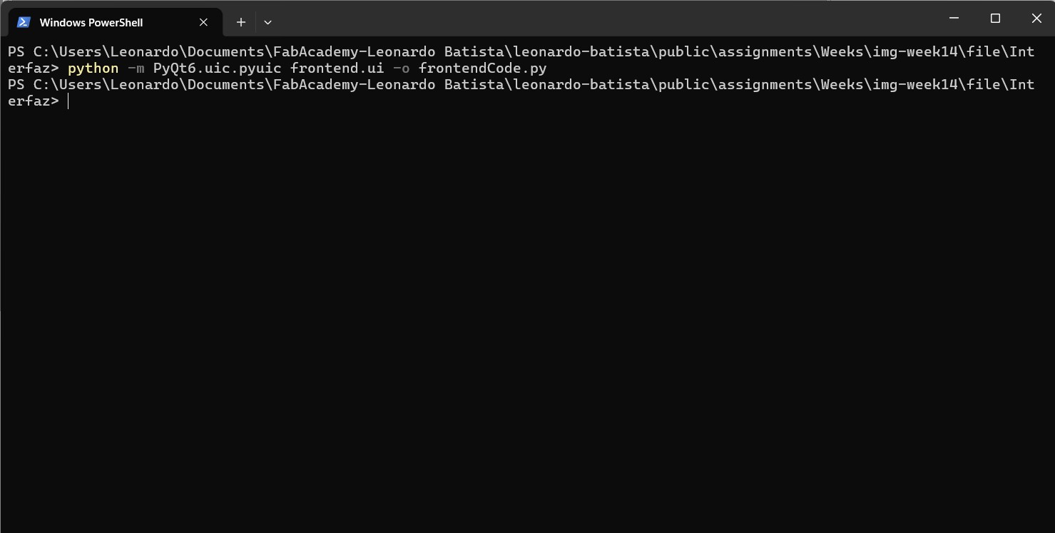
The generated Python file contains the interface structure, which can then be integrated with custom logic for controlling hardware and handling user interaction.
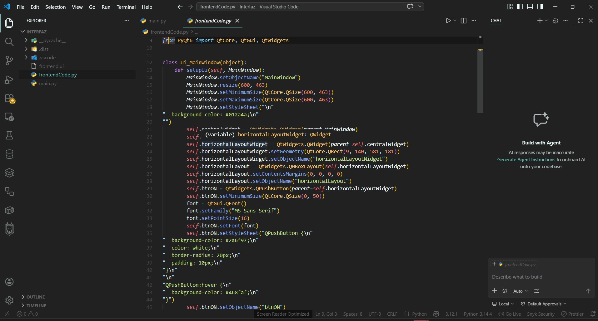
You can download the code below:
Download File
A separate file called main.py was created. This file is responsible for launching and executing the interface. The code can be seen in the following image.
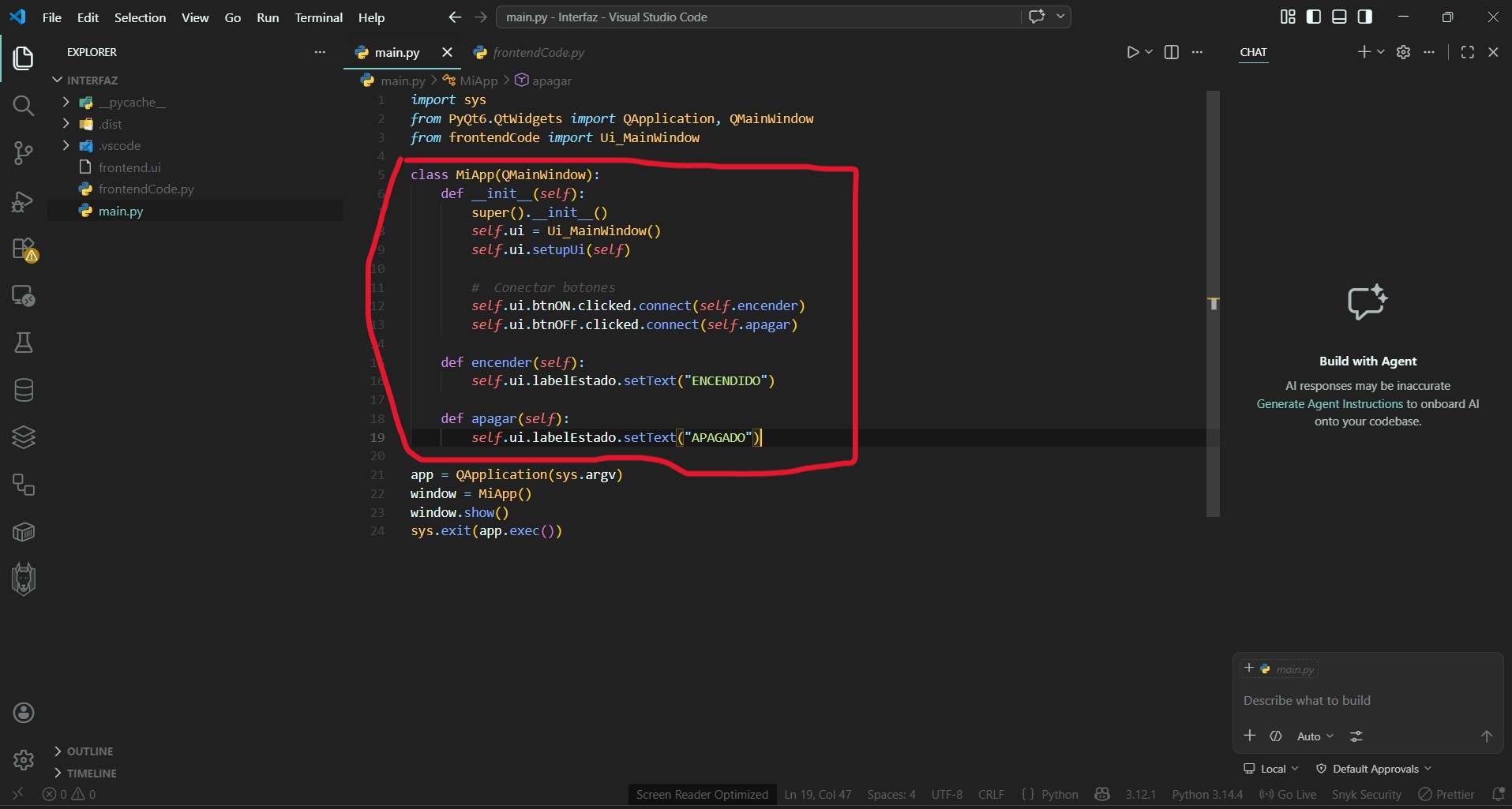
As shown in the image, the highlighted section is where the logic is implemented to establish communication between the microcontroller and the graphical interface.
Note: The file frontendCode.py should not be modified manually. It is automatically generated from Qt Designer. Any changes to the interface must be made in the .ui file, and then converted again into a .py file.
At this stage, the interface and its corresponding code were already completed. The next step was to establish communication between the PCB board and the application. For this purpose, I decided to use serial communication to exchange data between Arduino and Python.
To test this communication, I created a Python script and an Arduino program.
Download File
Below is the Arduino code used to test bidirectional communication between Python and the microcontroller. This program receives a command sent from Python and executes an action, such as turning on an LED.
Download File
The Arduino code receives the command and performs the corresponding action. In this case, it turns the LED on or off. The following video demonstrates the execution of this test.
It is important to note that at this stage, the communication is not yet integrated into the graphical interface. These tests were conducted to validate the communication process before integrating it into the final application.
As shown, a command is sent through serial communication, and the board receives and executes it successfully.
At this point, the system is ready to be integrated into the graphical interface.
Arduino Code for Controlling an LED from the Interface
In the loop() function, the system continuously checks for incoming serial data using Serial.available().
Each received character is read using Serial.read() and stored in a temporary buffer.
The message is constructed character by character until a newline character '\n' is detected,
which indicates that the complete command has been received.
Once the full message is ready, it is cleaned using trim() to remove unwanted spaces or line endings,
and then passed to the function procesarComando() for interpretation.
Inside this function, the received command is compared against predefined instructions such as
LED_ON, LED_OFF, PING, and STATUS.
Depending on the command, the system performs different actions like turning the LED on or off,
or sending a response back through the serial port.
After processing the command, the buffer is cleared and the system continues listening for new incoming messages, enabling continuous and responsive serial communication.
void loop() {
  while (Serial.available()) {
    char c = Serial.read();
    if (c == '\n') {
      messageReady = true;
    } else {
      inputBuffer += c;
    }
  }

  if (messageReady) {
    inputBuffer.trim();
    procesarComando(inputBuffer);
    inputBuffer = "";
    messageReady = false;
  }
}
In summary, this system acts as a serial command interpreter that receives text-based instructions, processes them, and executes corresponding actions on the hardware, such as controlling an LED or responding to status requests.
The function procesarComando() defines the available commands and their behavior.
It allows simple communication between a computer (or another device) and the microcontroller.
This approach enables modular and scalable control, where additional commands can be easily added to extend the system functionality.
void procesarComando(String cmd) {
  if (cmd == "LED_ON") {
    digitalWrite(LED_PIN, HIGH);
    Serial.println("[OK] LED encendido");

  } else if (cmd == "LED_OFF") {
    digitalWrite(LED_PIN, LOW);
    Serial.println("[OK] LED apagado");

  } else if (cmd == "PING") {
    Serial.println("[PONG]");

  } else if (cmd == "STATUS") {
    Serial.print("[STATUS] LED = ");
    Serial.println(digitalRead(LED_PIN) ? "ON" : "OFF");

  } else {
    Serial.print("[WARN] Comando desconocido: ");
    Serial.println(cmd);
  }
}
Next, I will explain the Python code corresponding to the main.py file.
This file acts as the main entry point of the application. It is responsible for initializing the graphical interface and establishing communication with the microcontroller through the serial port.
First, the required libraries are imported, including sys for application execution,
QApplication and QMainWindow from PyQt6 for the graphical interface,
and the custom modules that define the interface and handle serial communication.
The class MiApp inherits from QMainWindow, which allows it to function
as the main window of the application.
In the __init__() method, the graphical interface is initialized by creating an instance of
Ui_MainWindow and calling setupUi(self). This loads all the visual components
designed in Qt Designer into the main window.
A serial communication object is then created using the class ConectionSerial,
which establishes a connection with the Arduino board through the specified port
'COM7' at a baud rate of 115200.
The buttons from the interface are connected to their respective methods using the
clicked.connect() signal-slot mechanism.
The btnON button triggers the encender() method,
while btnOFF triggers the apagar() method.
self.ui.btnOFF.clicked.connect(self.apagar)
self.ui.btnON.clicked.connect(self.encender)
In the encender() method, a command "LED_ON" is sent to the Arduino
using the send() function of the serial connection object.
Then, the program waits for a response using get(),
and the received message is displayed in the label labelEstado.
Similarly, the apagar() method sends the command "LED_OFF"
to turn off the LED, retrieves the response from the Arduino,
and updates the interface with the received status.
def encender(self):
    try:
        self.Conection.send("LED_ON")
        data = self.Conection.get()
        self.ui.labelEstado.setText(data)
    except Exception as e:
        print(f"[Error] -> {e}")
Both methods include a try-except block to handle potential communication errors,
ensuring that the application does not crash if something goes wrong during serial transmission.
The closeEvent() method is overridden to properly close the serial port
when the application window is closed. This prevents the port from remaining locked
or causing access errors in future executions.
def closeEvent(self, event):
    self.Conection.closeSerial()
Finally, the application is launched by creating an instance of QApplication,
initializing the main window class MiApp, and executing the event loop
using app.exec(), which keeps the interface responsive and running.
In summary, this application acts as a graphical interface that communicates with an Arduino device through serial communication. It allows the user to send commands using buttons and visualize real-time responses from the microcontroller, providing a simple yet effective human-machine interface.
Download File
Within the main.py program, methods such as send() and get() are used.
These methods belong to a separate file that defines the ConectionSerial class,
which is explained in the following section.
The class ConectionSerial is designed to handle serial communication between the Python application
and an external device such as an Arduino. It encapsulates all the logic required to send and receive data
through a serial port in a clean and reusable way.
In the __init__() method, the serial connection is initialized using the parameters
port, baudrate, and timeout.
The connection is established using serial.Serial(), which opens the communication channel
with the specified configuration.
self.ser = serial.Serial(port=self.port, baudrate=self.baudrate, timeout=self.timeout)
The send() method is responsible for transmitting data to the connected device.
Before sending, it verifies that the serial port is available and open using is_open.
If the connection is not valid, it raises a ConnectionError.
The message is sent as a string followed by a newline character '\n',
which acts as a delimiter for the receiving device. The message is encoded using UTF-8
before being transmitted.
self.ser.write((mensaje + "\n").encode('utf-8'))
Additionally, the method prints a timestamped log using datetime.now(),
which is useful for debugging and tracking communication events.
The get() method is used to receive data from the serial port.
It also validates that the connection is active before attempting to read.
The method reads a full line using readline(), decodes it from UTF-8,
and removes trailing whitespace using rstrip(), returning a clean string.
data = self.ser.readline().decode('utf-8').rstrip()
The closeSerial() method safely closes the serial connection using close().
This is important to release the port and avoid access errors when reopening the connection later.
self.ser.close()
In summary, this class acts as a communication interface that abstracts the low-level details of serial communication. It provides simple methods to send commands and receive responses, making it easier to integrate hardware control into higher-level applications such as graphical interfaces.
Download File
The following section demonstrates the interface in operation, interacting with the PCB board.
As shown in the video, every time the ON button is clicked on the interface, the green LED turns on, and each time the OFF button is pressed, the LED turns off.
What I Learned
This week I learned how to use a very practical tool like Qt Designer. I had never used it before. Although I previously worked with Tkinter to create graphical interfaces in Python, Qt Designer significantly streamlines the development process, allowing me to focus more on the desired functionality and final outcome.
Mission accomplished! 😊