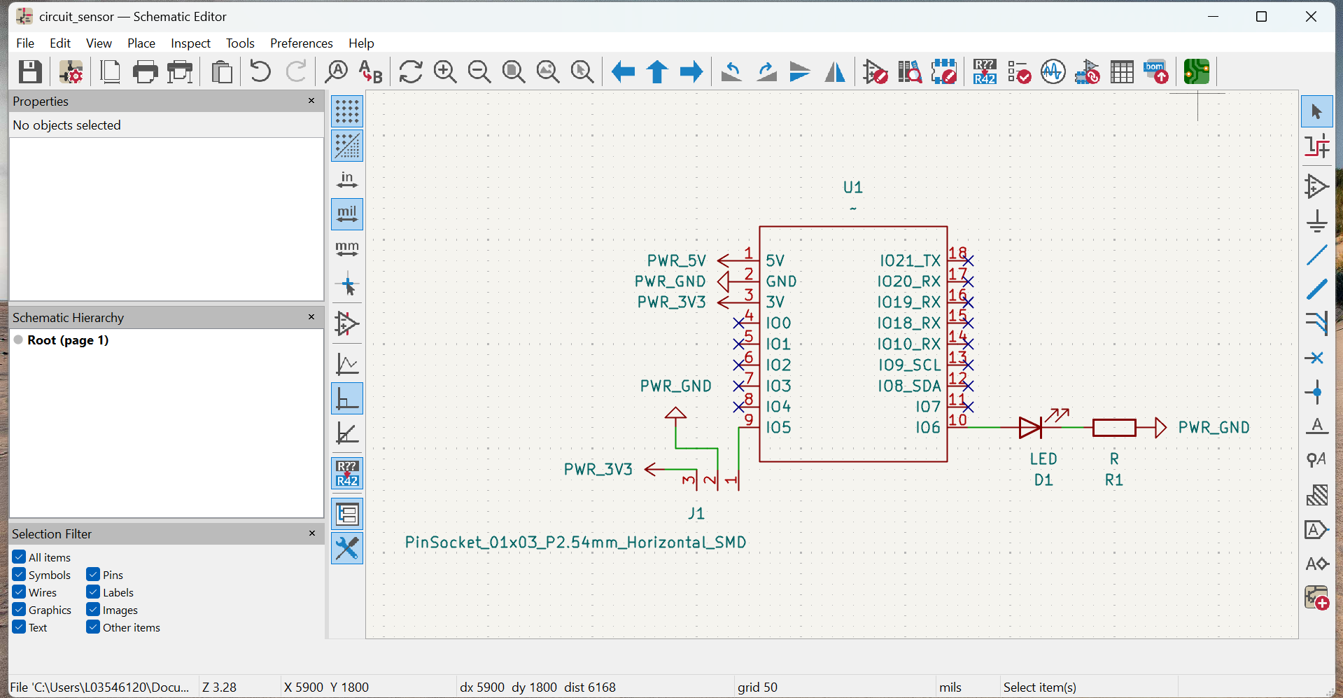
9. Input devices
Group AssignementThis week I learned how to test, read and integrate input devices into my PCBs.
Some of of my learnings:
- Again, make sure footprintes, schematics and connections are done correctly if a new PCB will be created.
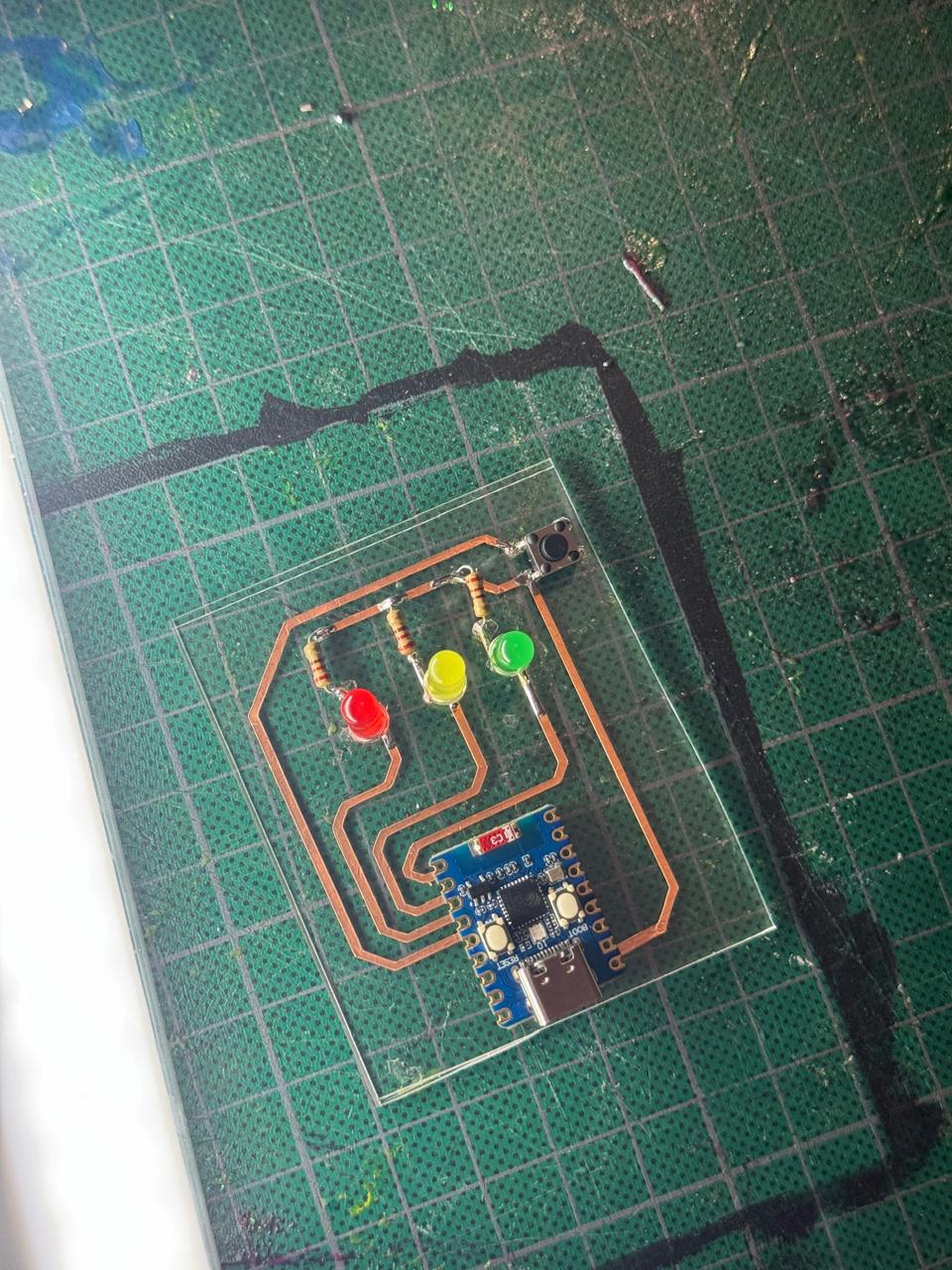
- Creating PCBs with the vinil cutter and copper tape can make the iteration process SO flexible.
- Also using acrilic made it very simple to iterate and adapt along the way.
- Testing every connection is key
- Sensors may need some calibration
My process for this week's assignement was a little improvised and chaotic but it turned out great (and it was really fun)
- First I started designing a brand new PCB from scratch because I though I had 2 microcontrolers (one used for ñast last week's assignement, another one left)...
- Turned out I lost or didn't get the second microcontroler, so I decided to reuse last week's PCB and see if I could just add the sensor.
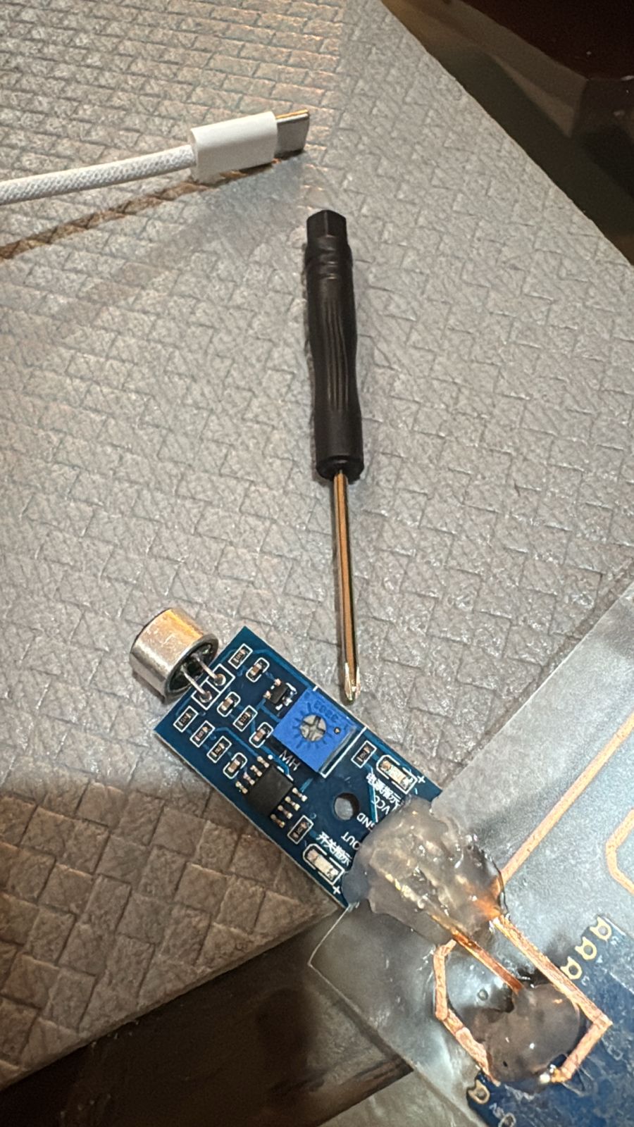
- I analyzed my micronphone sensor, measured, played around with orientation and sketched some paths with marker over the acrilic. It all looked good in theory XD I just had to use the other phase of the acrilic, creating my own DIY inter-phase paths.
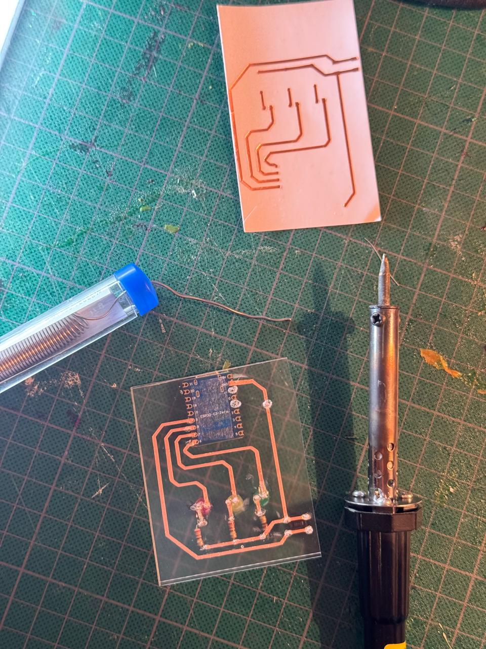
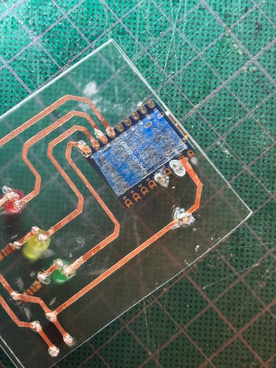
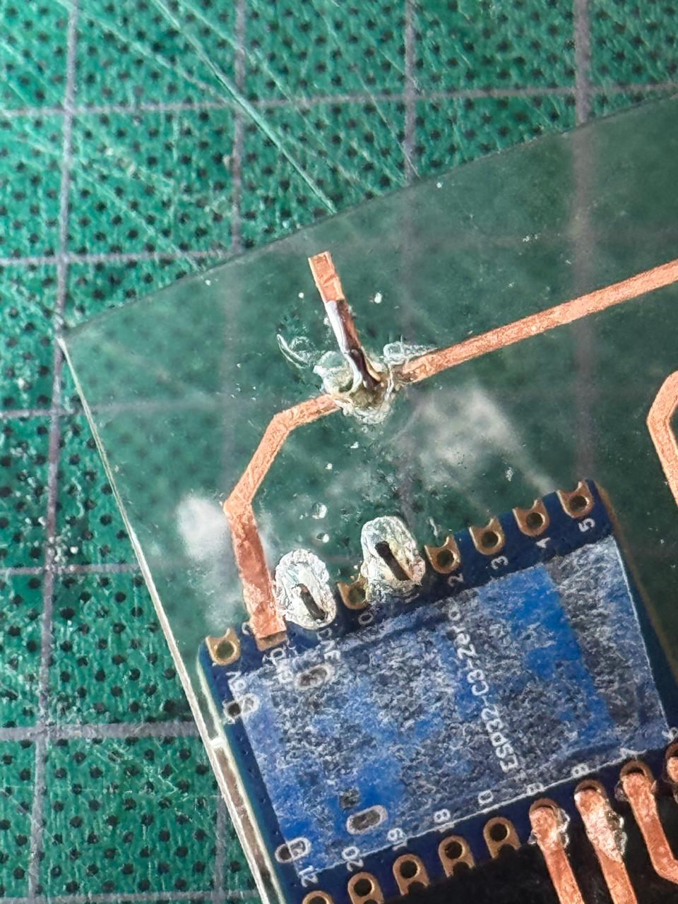
- Made the holes I needed to connect the 3 pins of my microphone sensor: OUT, GND and V. Thinking it shouldn't be too complicated, fully trusting my soldering skills and my vision.
- Added some single pins and copper tape from last week's spare cut manually to create my tracks. (Crossing my fingers with every move)
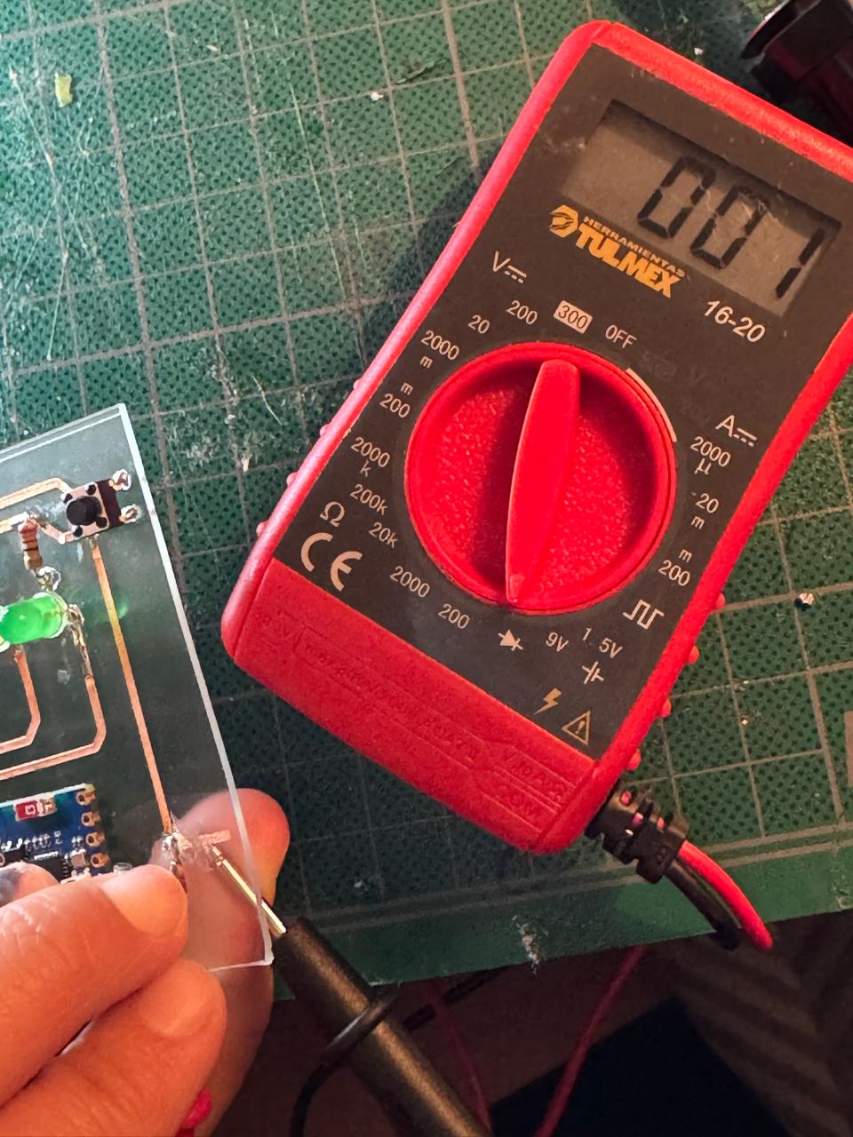
- Tested every connection and made any necessary adjustments
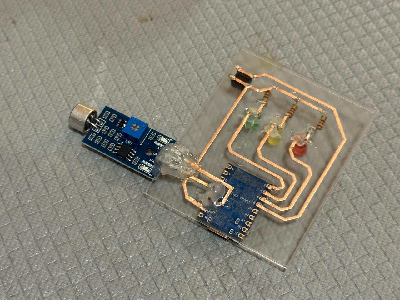
- Secured and covered all important (or loose) connections with silicone to get the final PCB
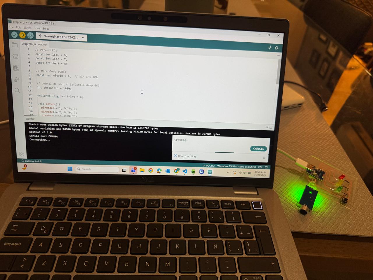
- Uploaded a new Code to the microcontroler
-
INPUT_PULLUP
In this code, the line
pinMode(buttonPin, INPUT_PULLUP);configures the button pin as an input with the ESP32's internal pull-up resistor enabled. This keeps the pin at a stable HIGH state when the button is not pressed, preventing random or false readings caused by electrical noise. When the button is pressed, the pin is connected to GND and reads LOW. UsingINPUT_PULLUPeliminates the need for an external resistor, simplifying the circuit and making button detection more reliable. -
Analog Reading
The
analogRead()function is essential because it converts the microphone's analog voltage signal into a digital value that the microcontroller can process. This allows the ESP32 to read changes in sound intensity and use those values to trigger actions in the system. -
Threshold Detection
The threshold value is important because it defines the minimum sound level required to trigger an action. This helps filter out background noise and ensures that only intentional or stronger sounds are detected by the system.
-
Serial Monitoring
Serial monitoring was useful during development to visualize the microphone readings in real time. This made it easier to test the sensor, understand the range of values, and choose an appropriate threshold for the environment.
- Tested and calibrated the sensor
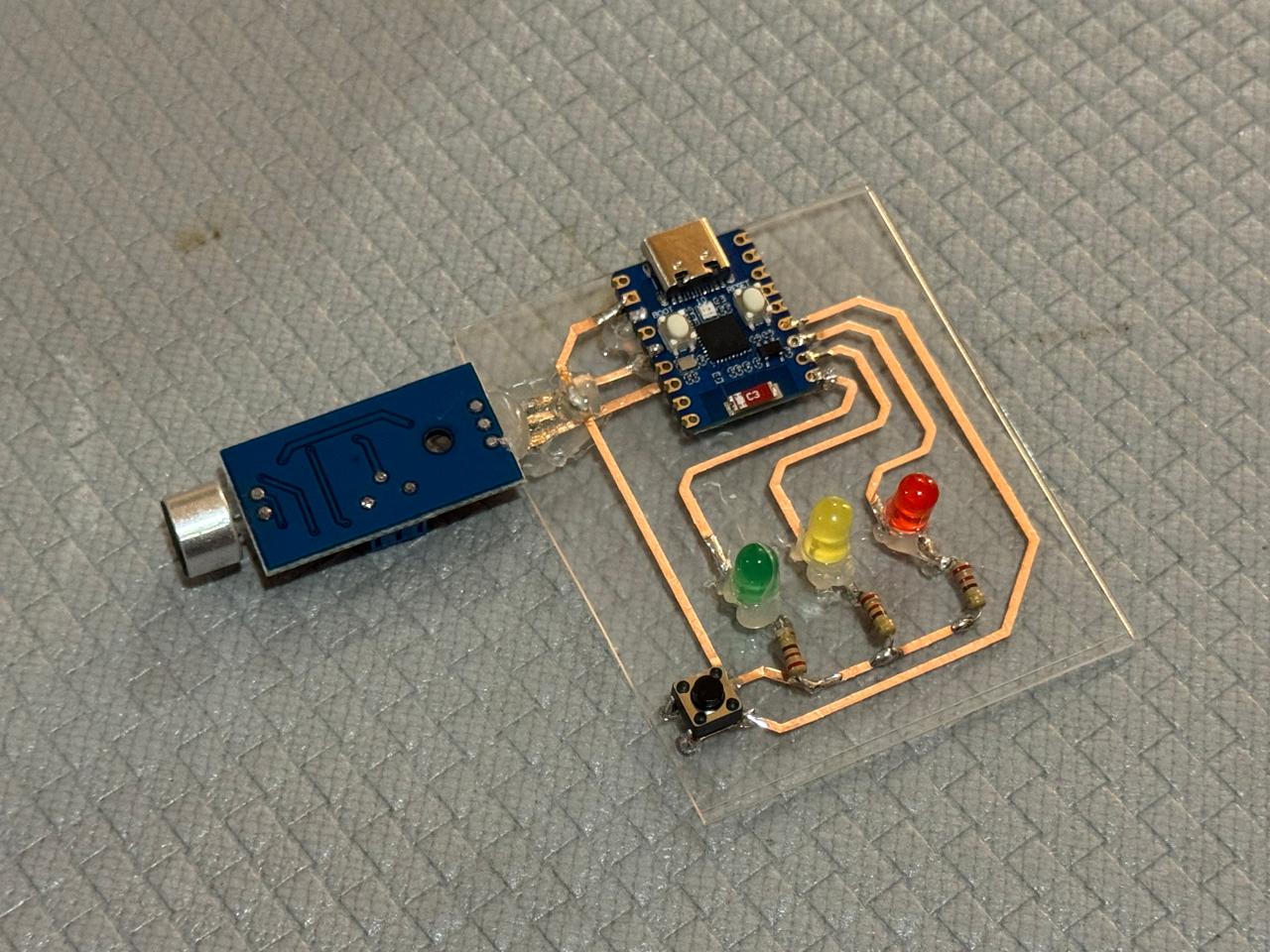
- Got my hacked pcb working :D
Some important notes about the code:
I'm so happy and proud I made this work.
For my final project...
I am using a HC SR501 PIR Motion Sensor to activate a servo motor, an LED and a screen:
Go to final project page to see more of it's implementation.
Download all files