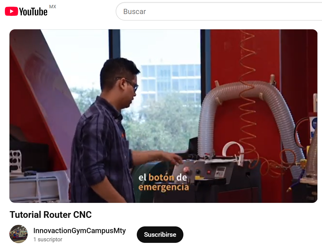
7. Computer-controlled machining
Group AssignementThis week I learned how to bring my 2d digital designs into a code that can be processes through a big format machining tool called Router CNC.
Some things to take into consideration beforehand:
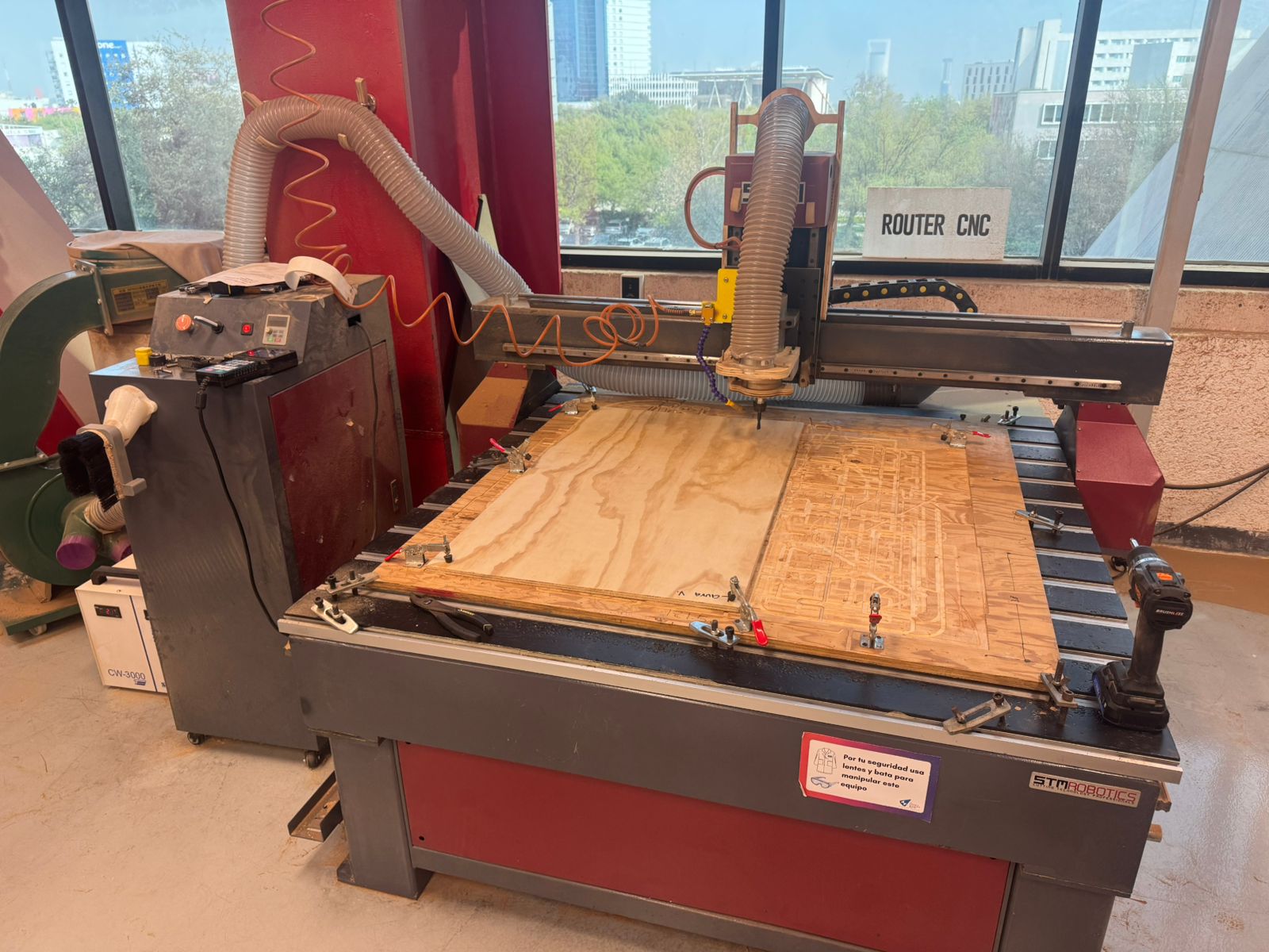
- The router works similarly to a 3D printer (with x,y and z axis), but intead of having a hot end nuzzle, the router changes cutting tools according to the material and process.
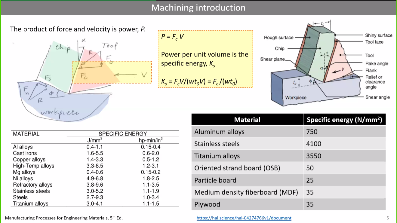
- Forces and frition between the cutting tool and the material have to be estimated and taken into consideration in order to make the right choices and avoid any problems.
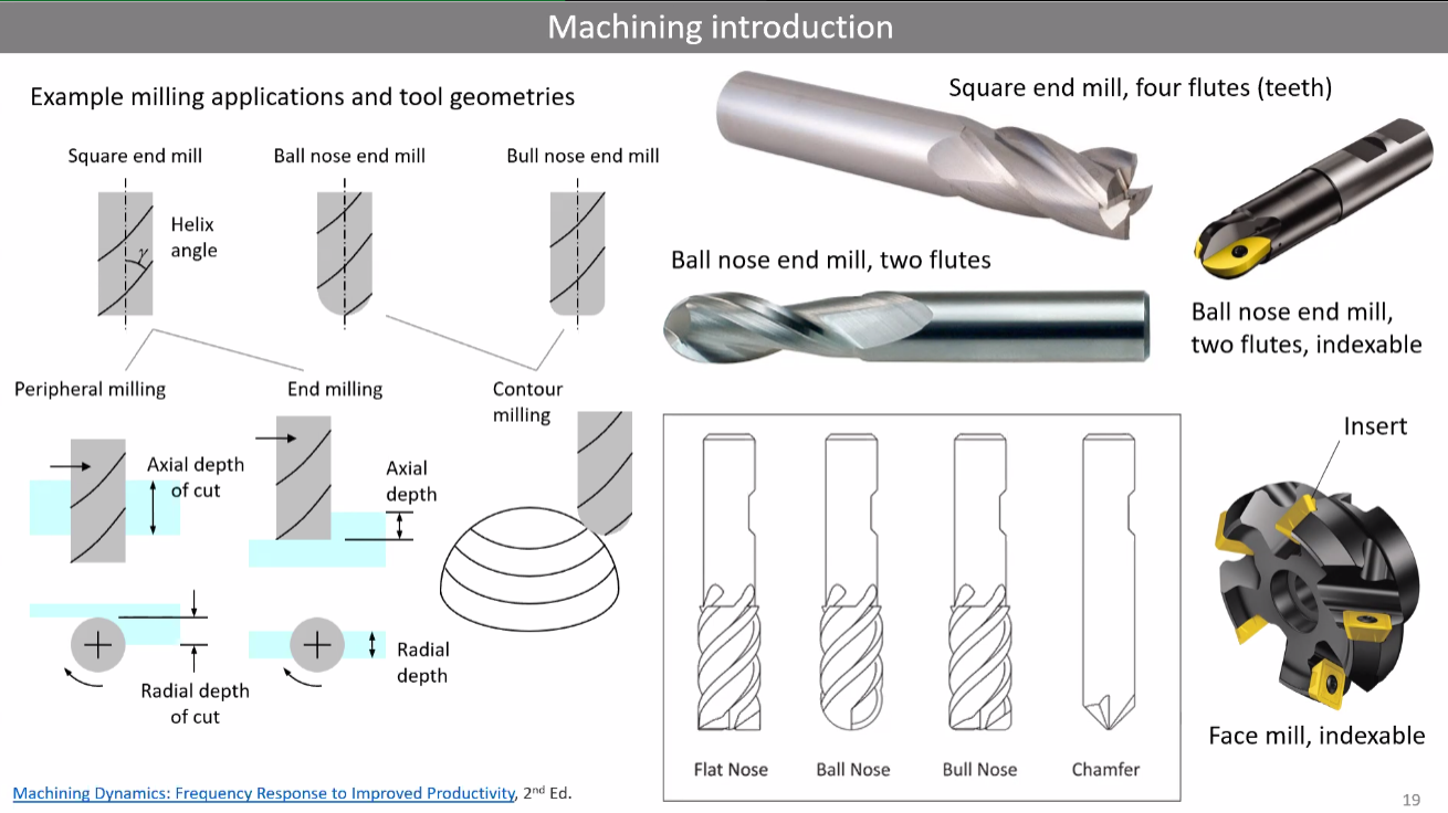
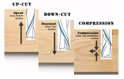
- Chips are always generated during the processes. It is important to look for the tool design that best adapts to the material's behaviour.
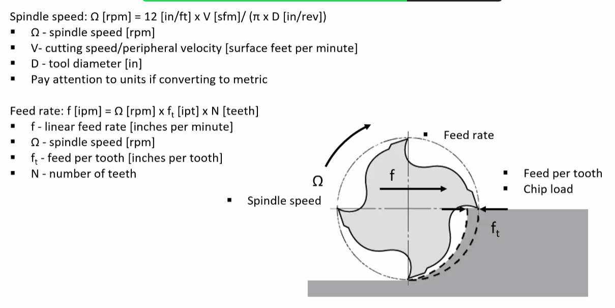
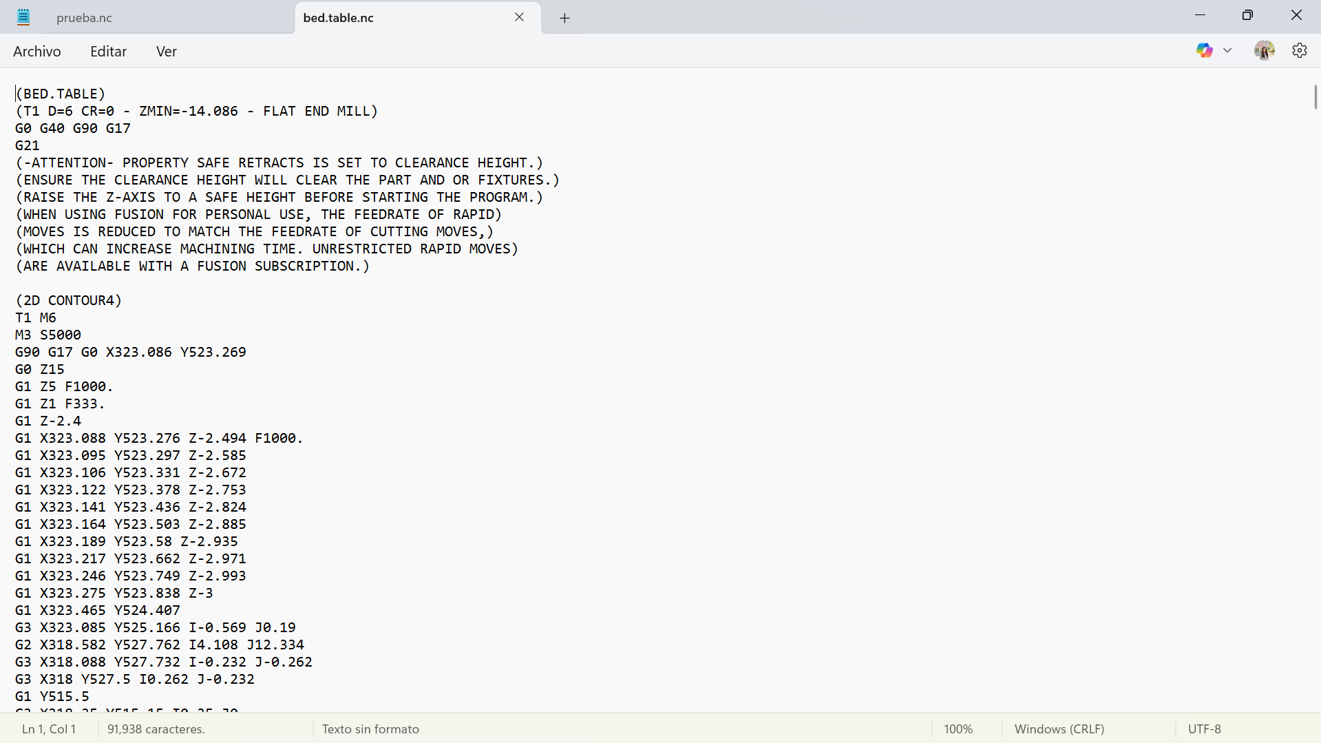
- The type of code that the router cnc tipically needs is a G Code and it's structure goes as follows:.
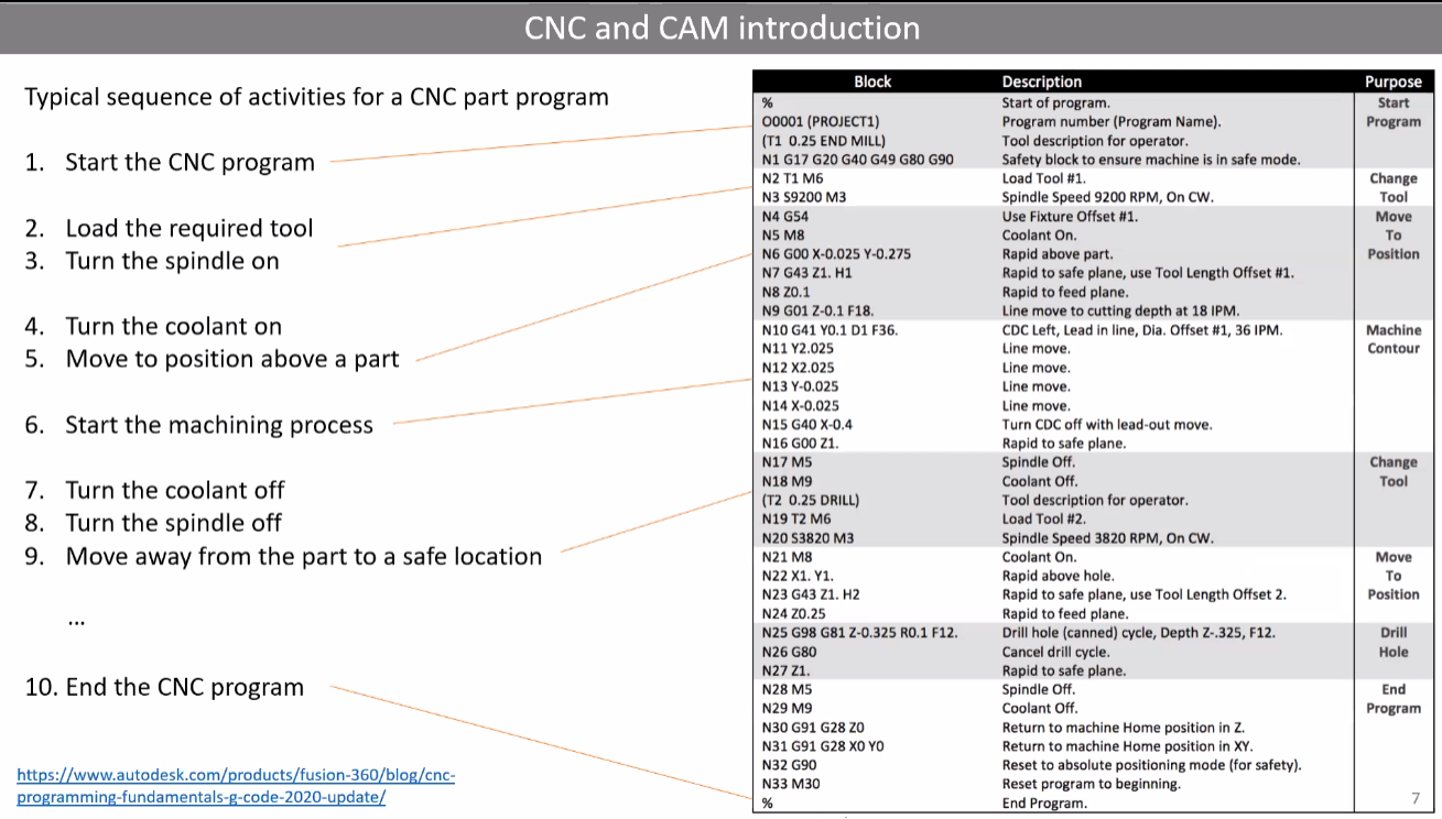
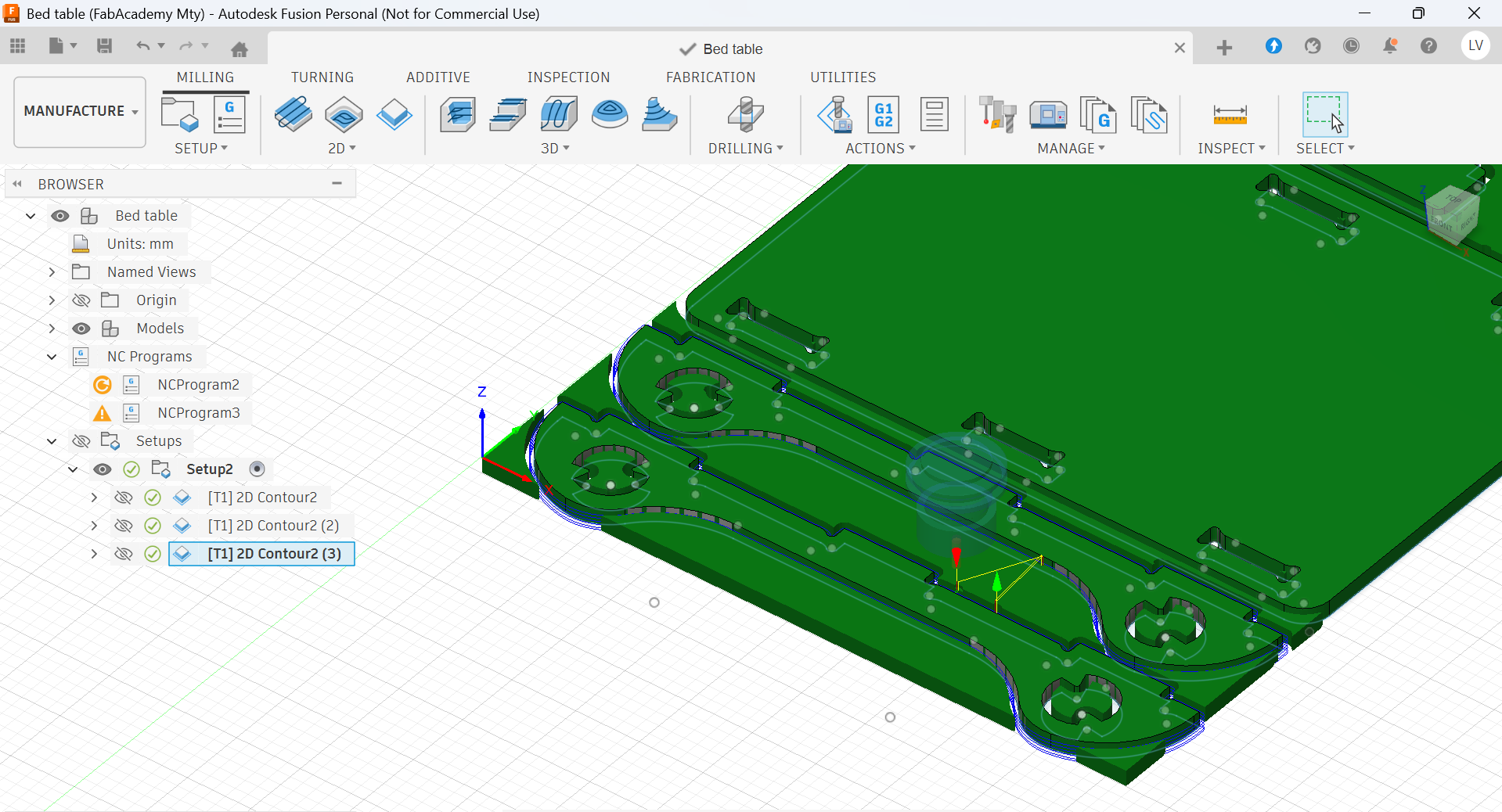
Code generation
Half of the process goes into generating the code. A G-Code is a series of setups and instructions that tell the machine all about the material´s dimensions, cutting tool, lines to follow and depths to cut.
Here are the steps I followed for this week's assignement:
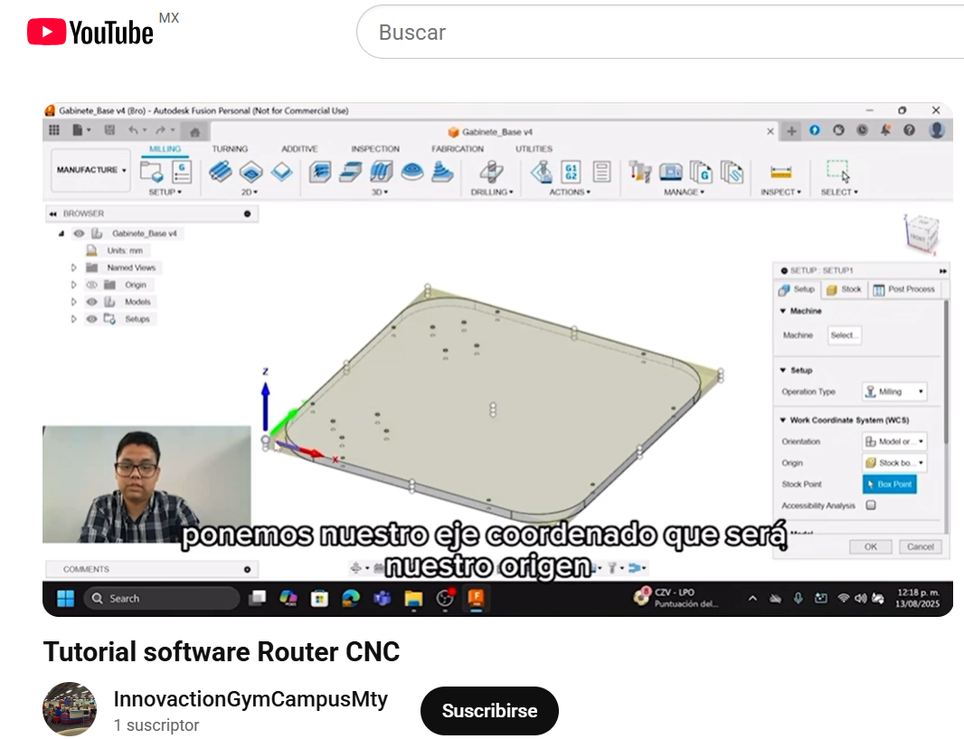
- Watching my local lab's tutorial
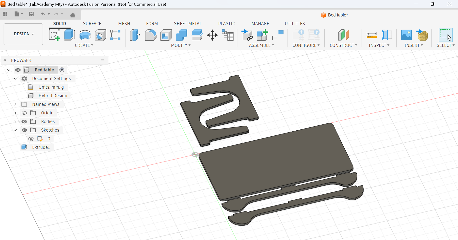
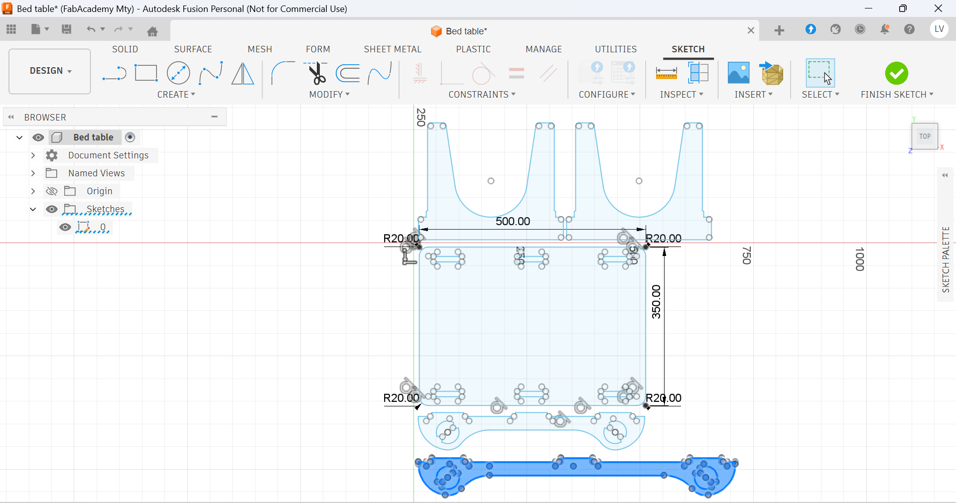
- Sketching my design
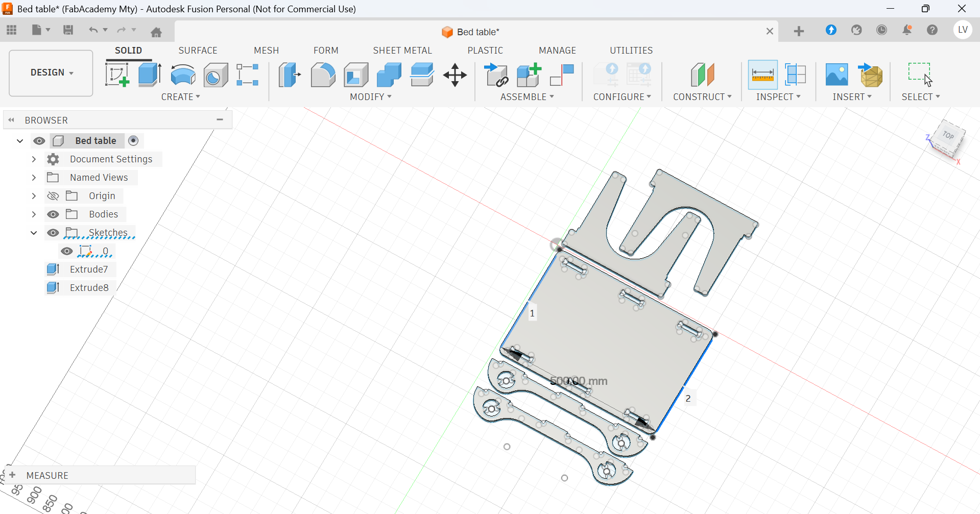
- Extruding the design to my material's width
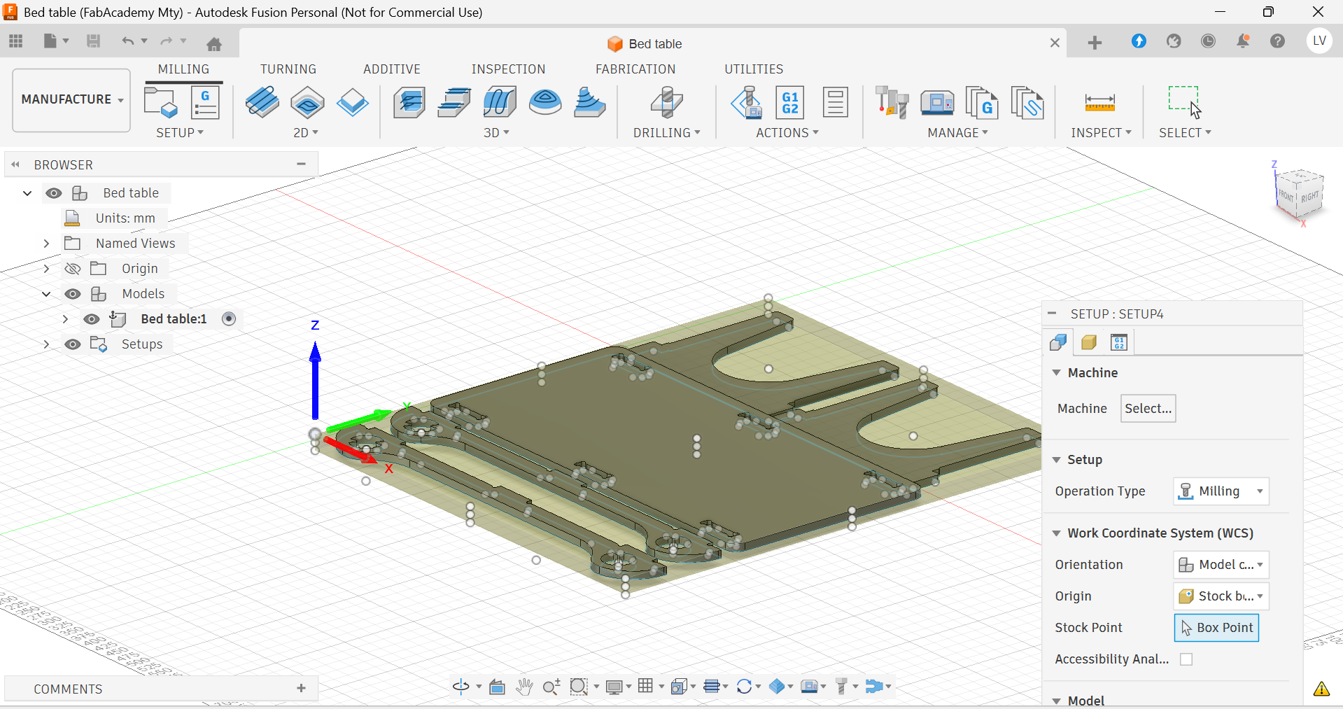
- Setting and origin in the design
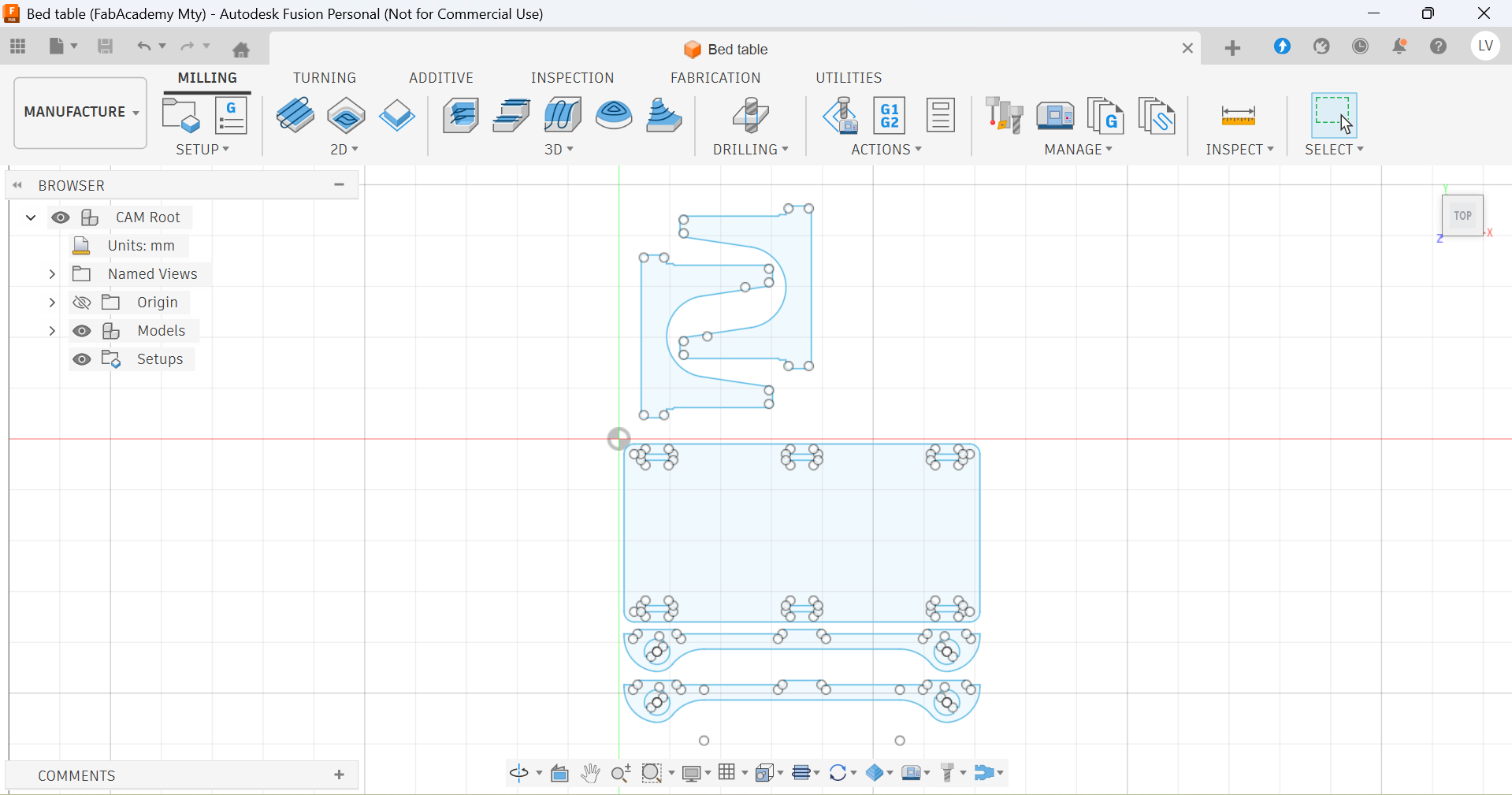
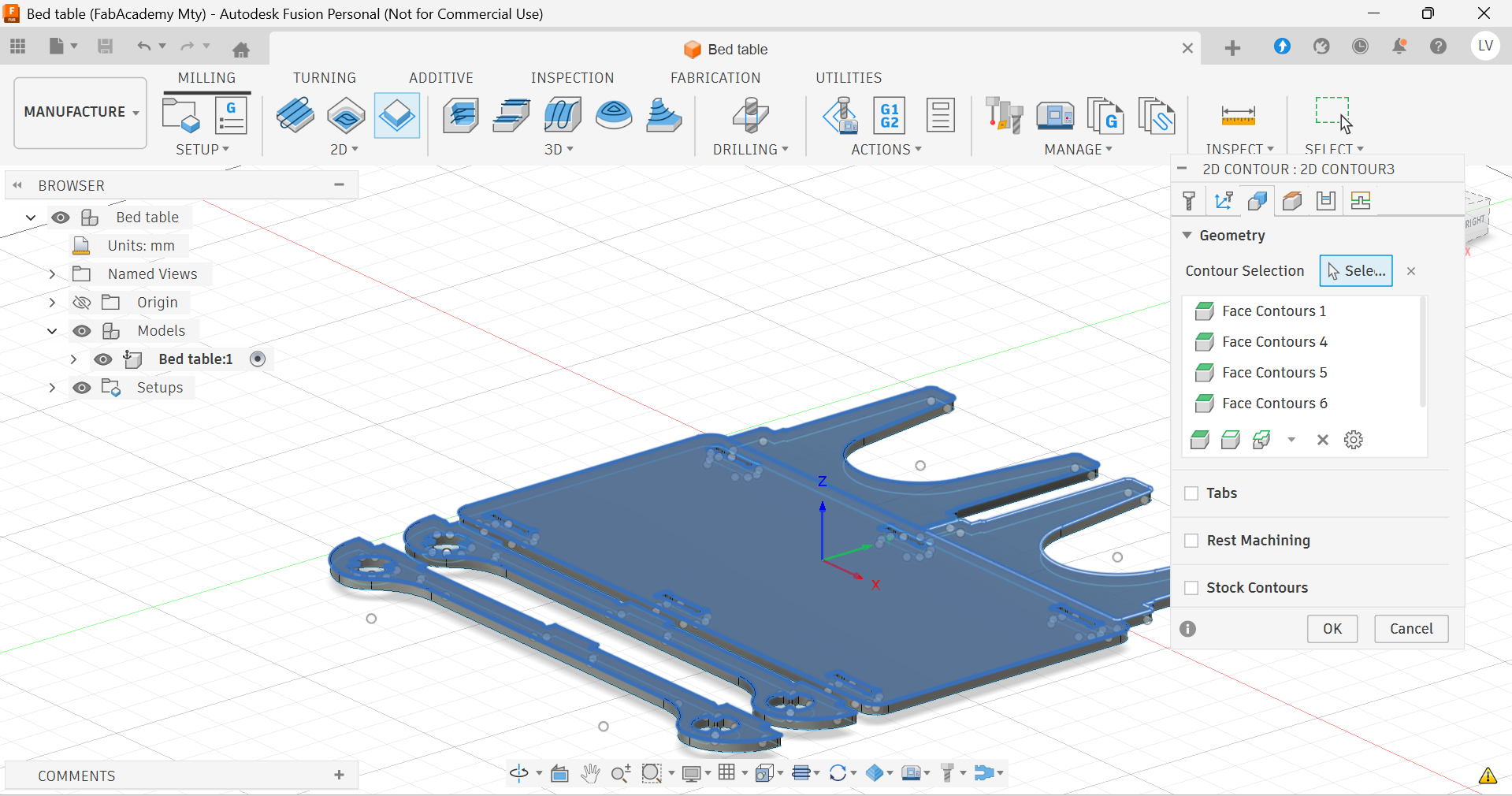
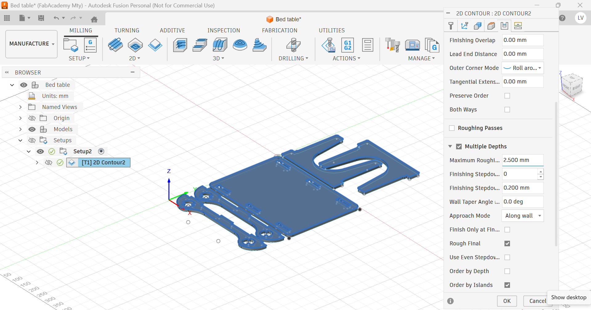
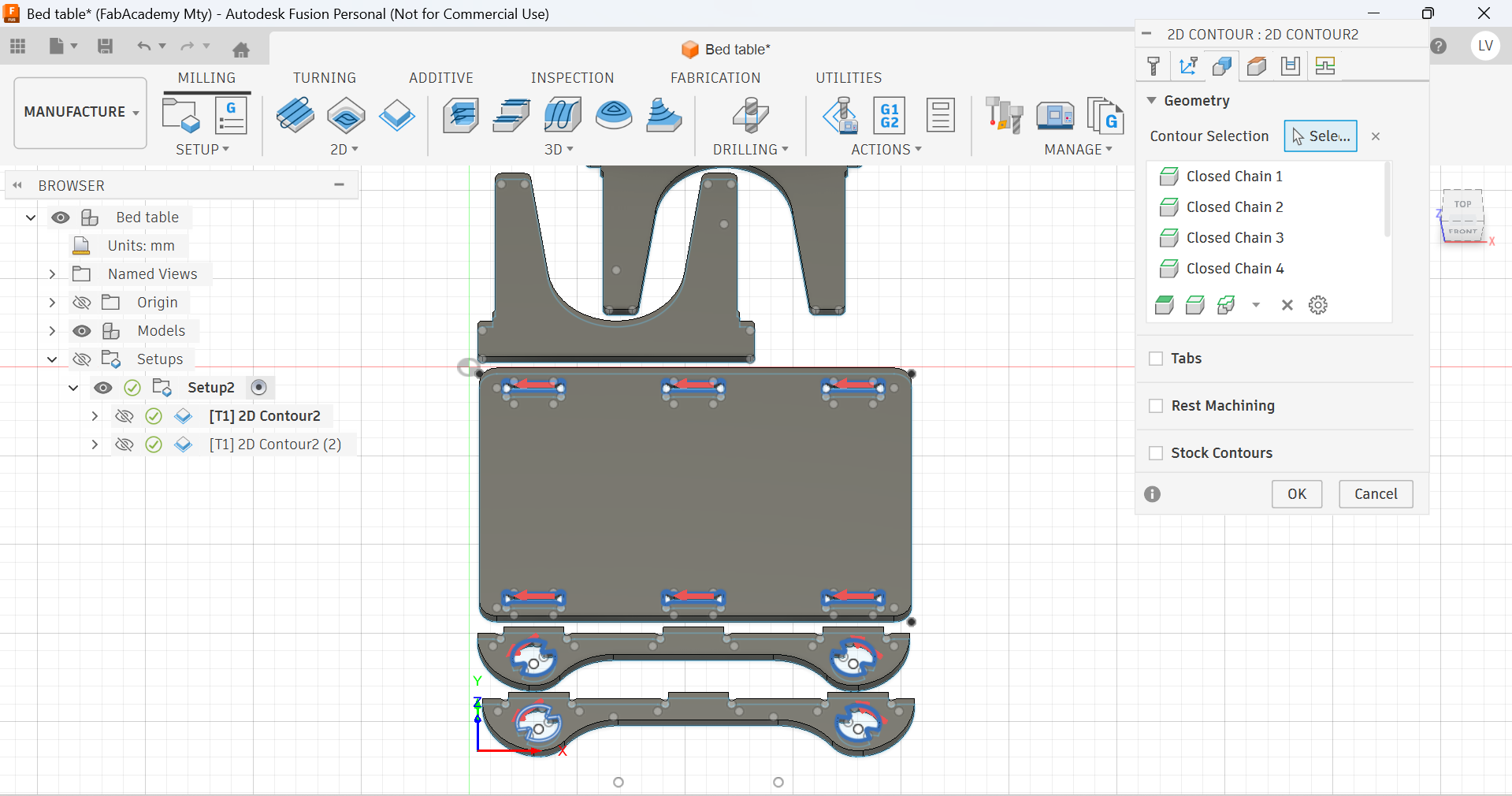
- Choosing a process and the paths it includes
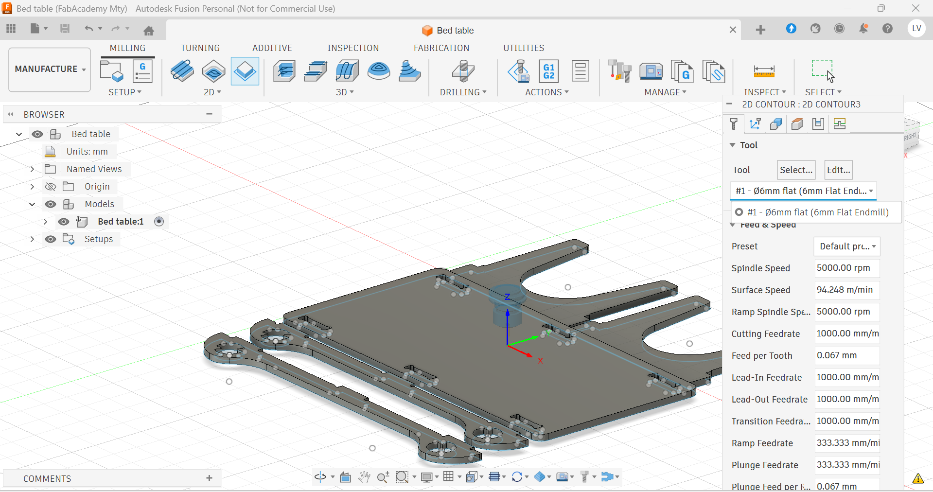
- Selecting the cutting tool
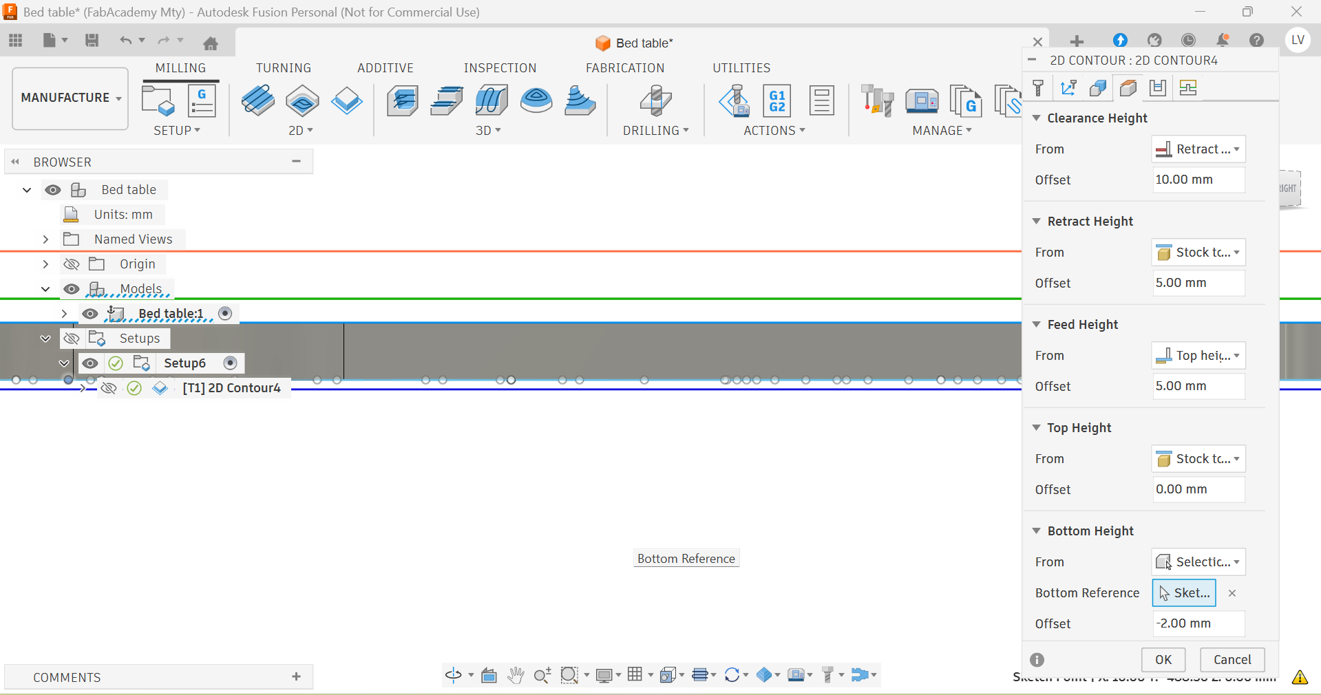
- Defining the total depth of the cut (width of the material +2mm)
- Indicating the depth for each pass.
- Simulating the process to check everything is fine
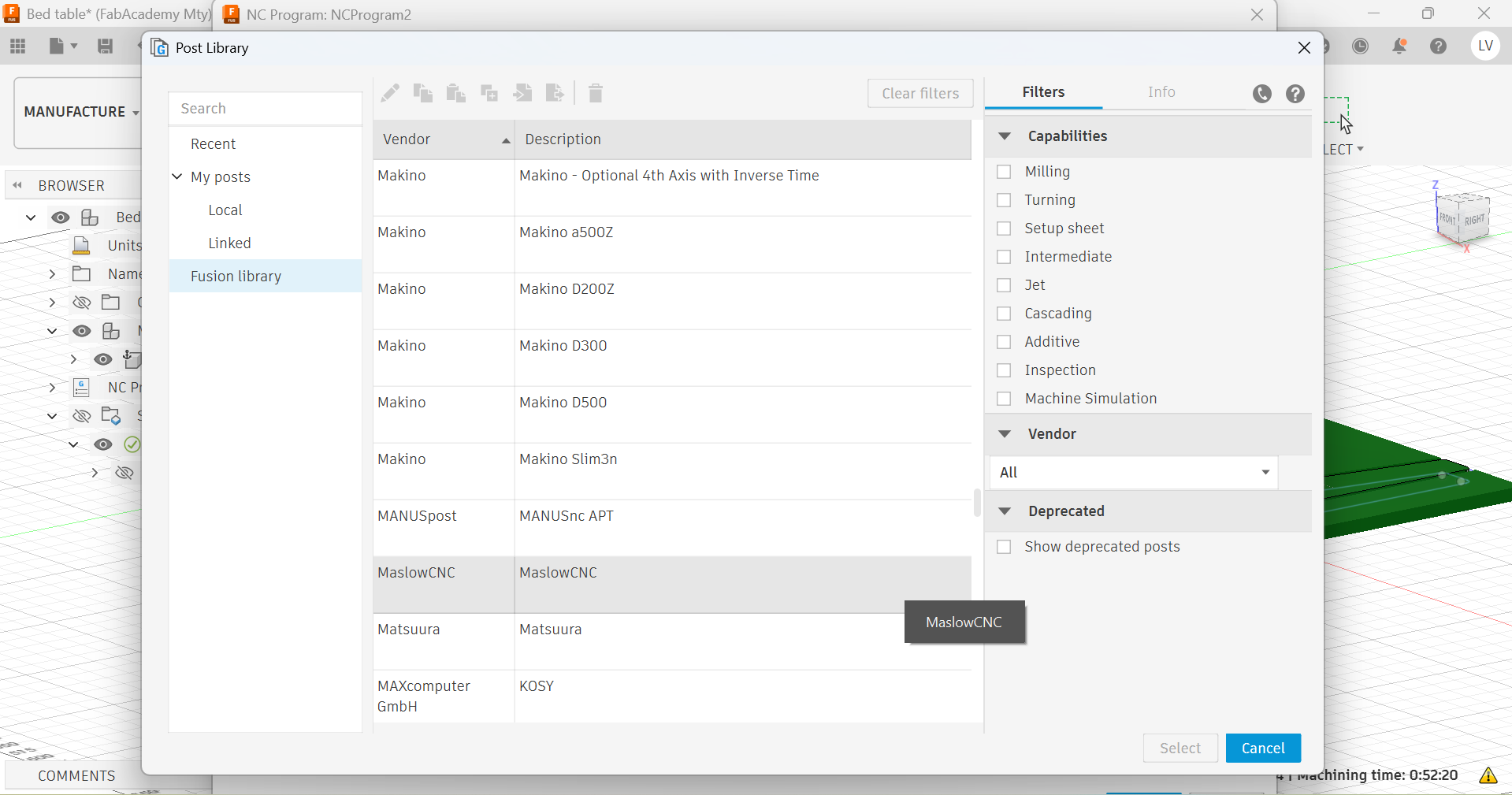
- Post-processing with the right library (compatible with the machine)
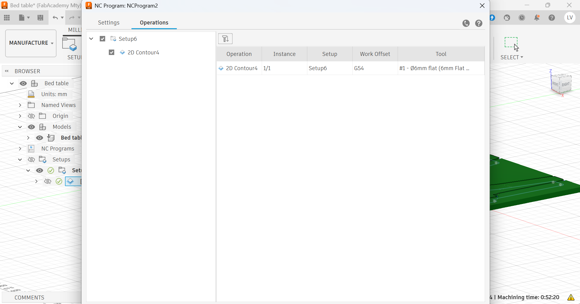
- Selecting the operations to be included in the code
- Generating the code
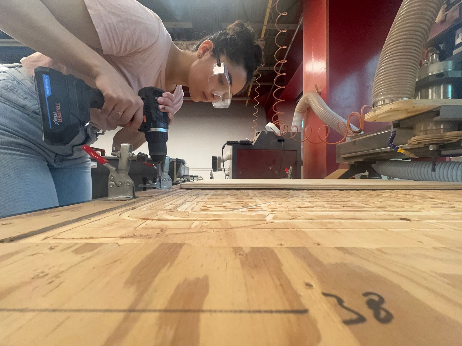
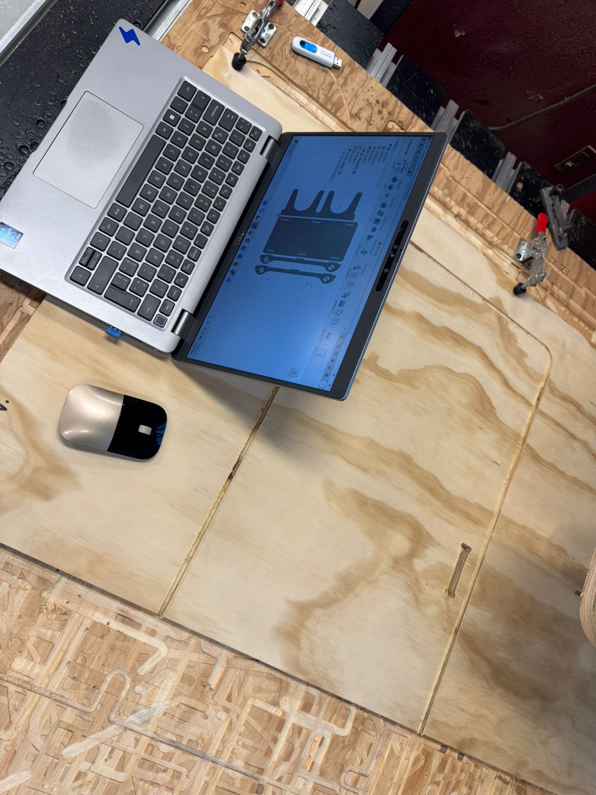
Machining
The second part of the process becomes more manual as the code is loaded to the machine, as well as the material and cutting tool to proceed with the cuttings.
My process went as follows:
- Watching my local lab's tutorial
- Campling the material to the router's bed
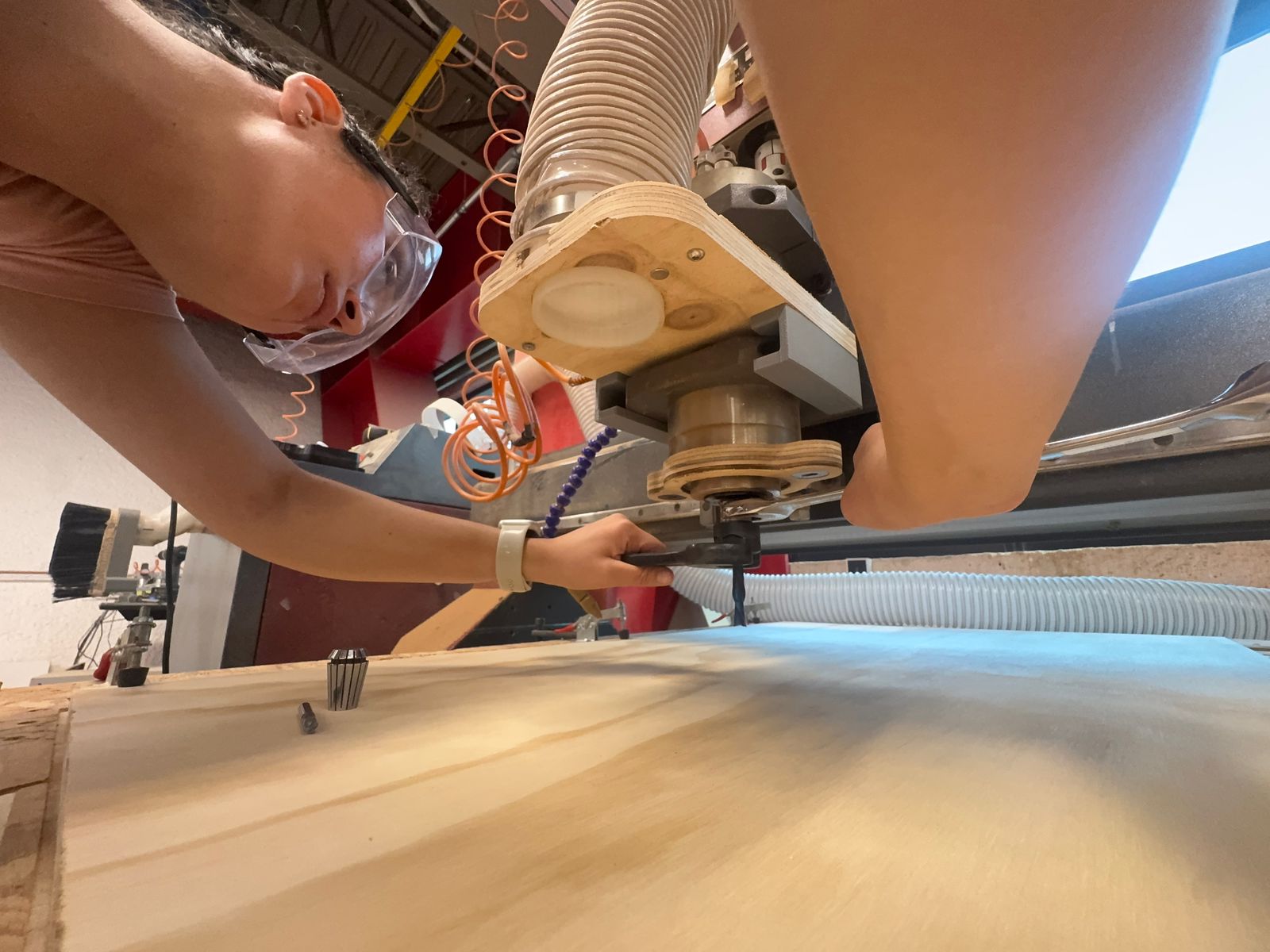
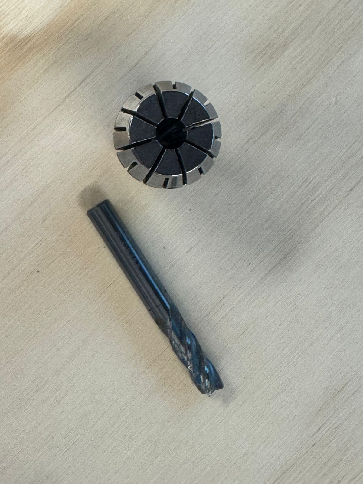
- Putting the right tool on (6mm Flat End Mill with 4 flutes in my case, with its corresponding collet).
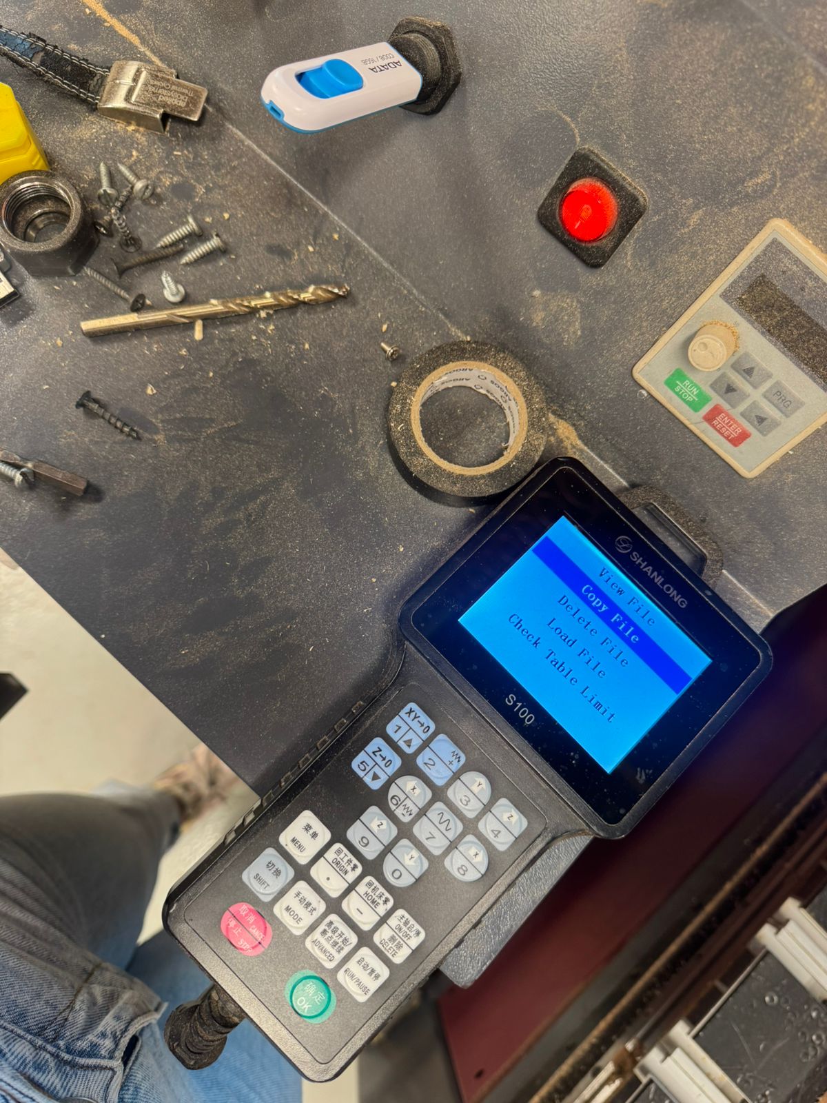
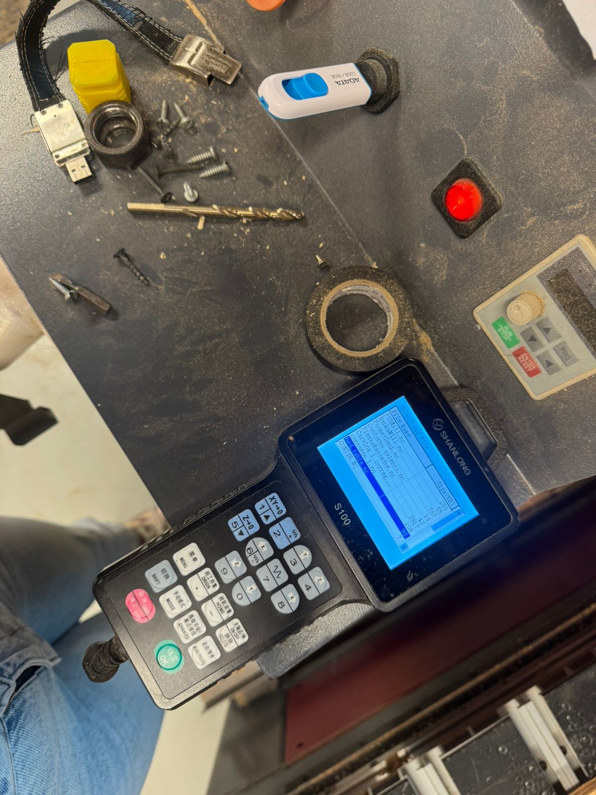
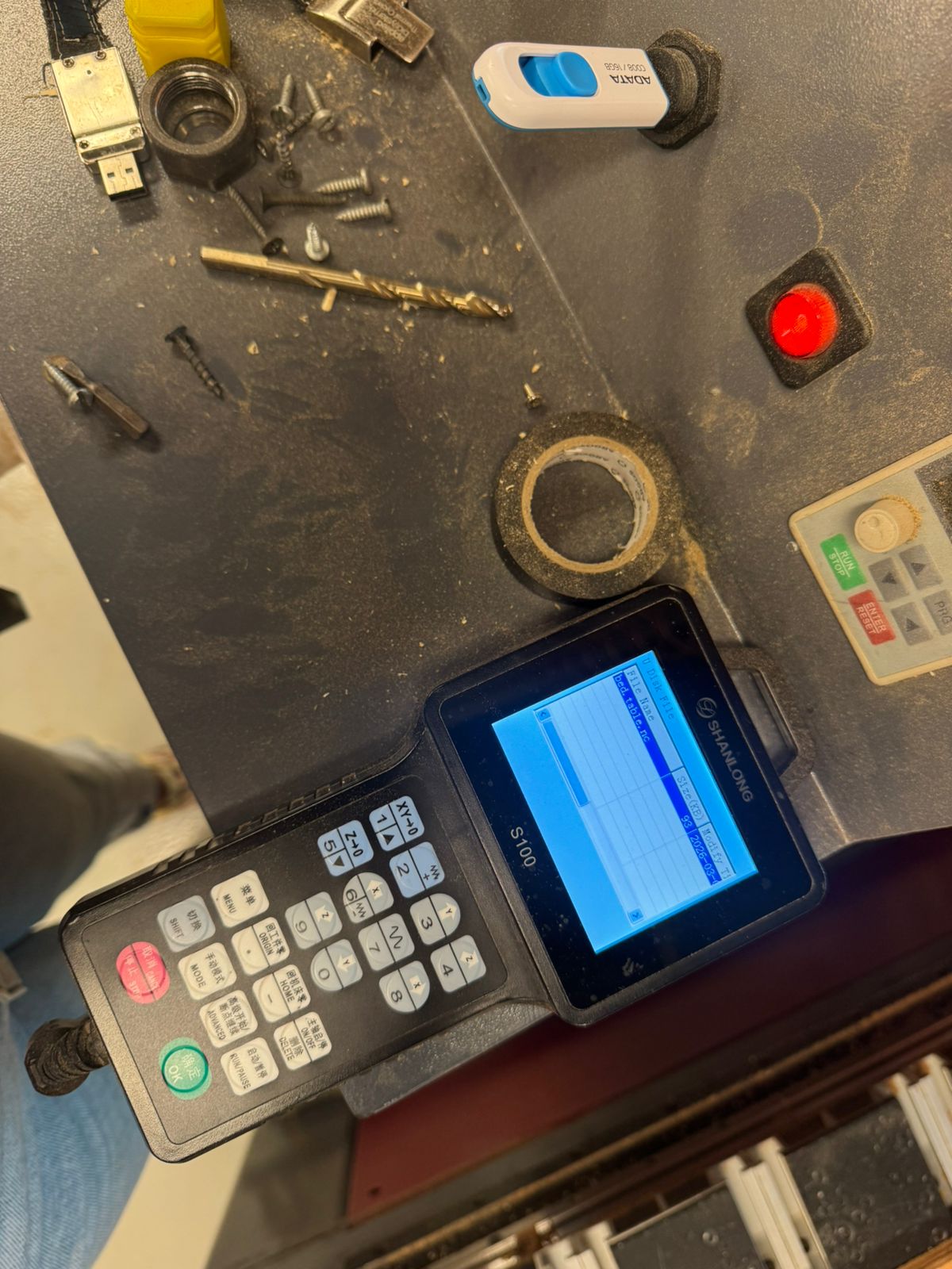
- Copying the code from a USB
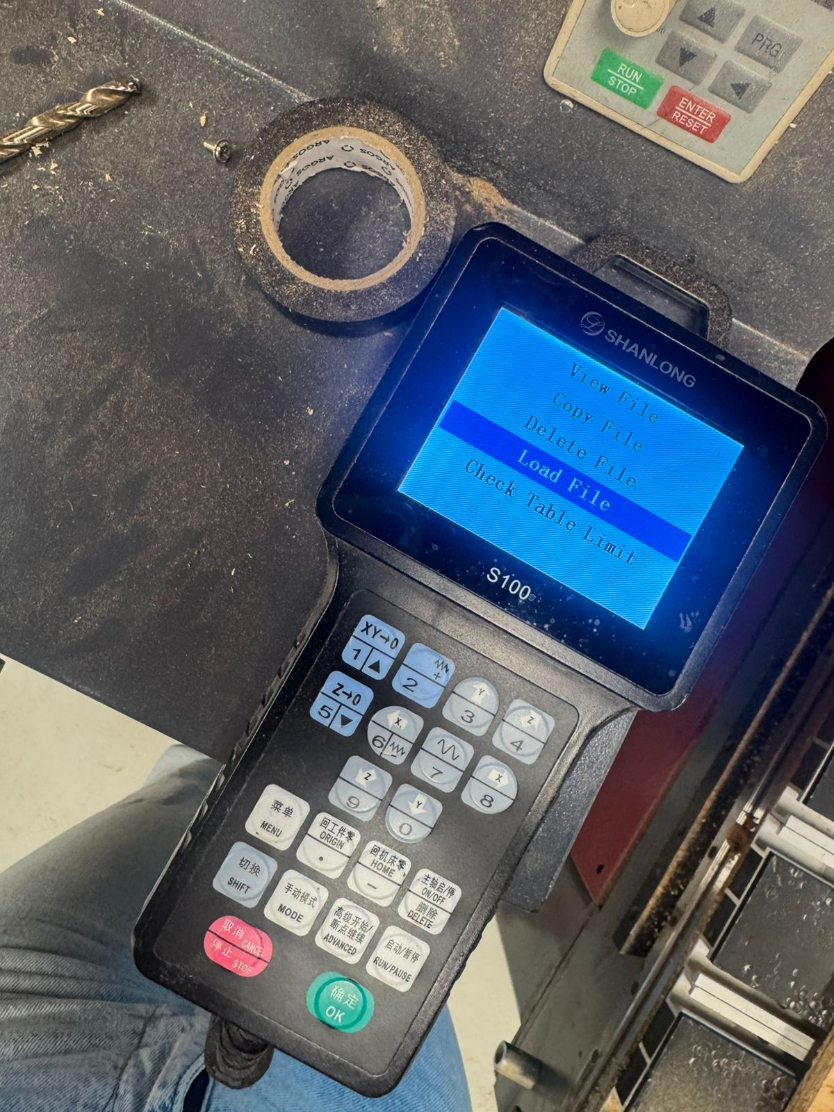
- Loading the file
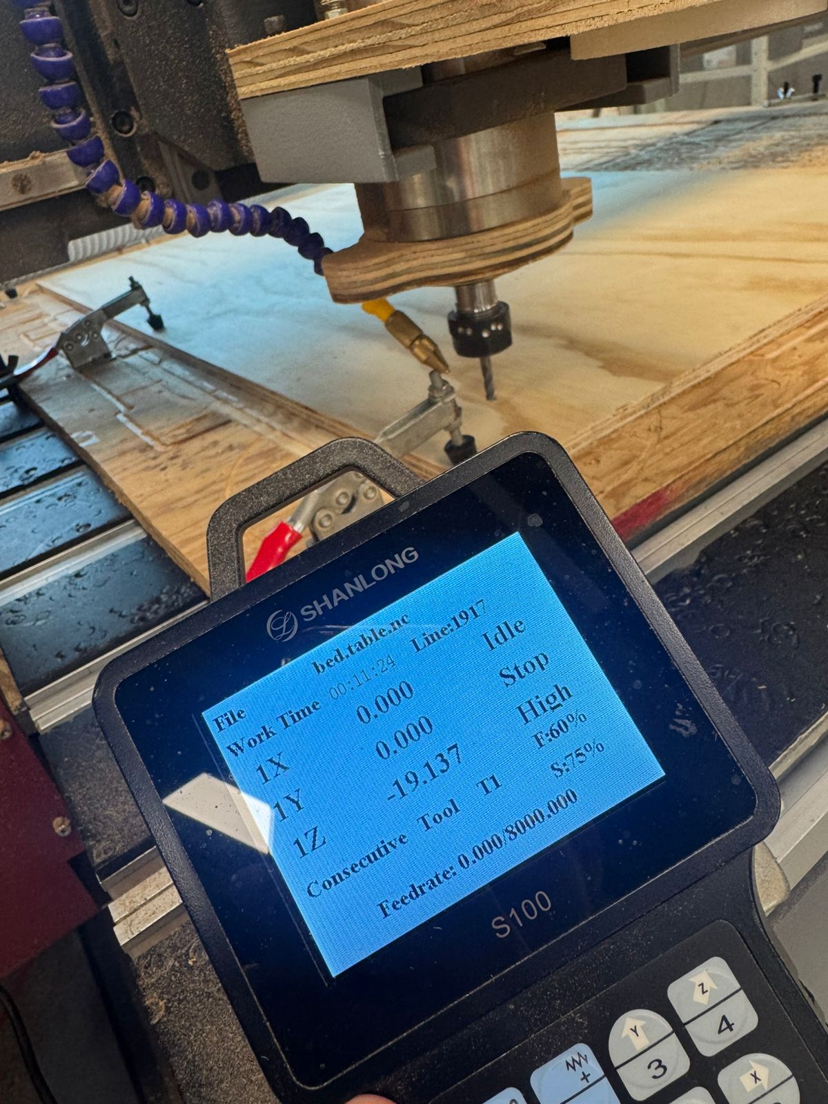
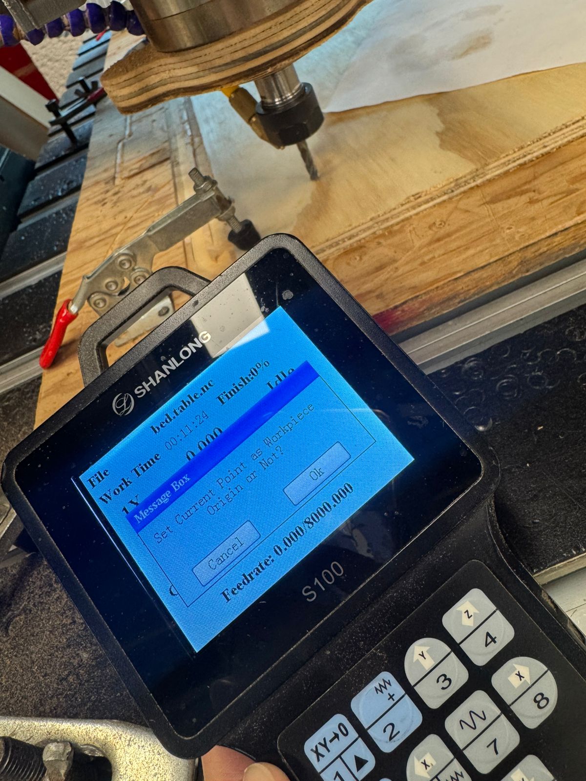
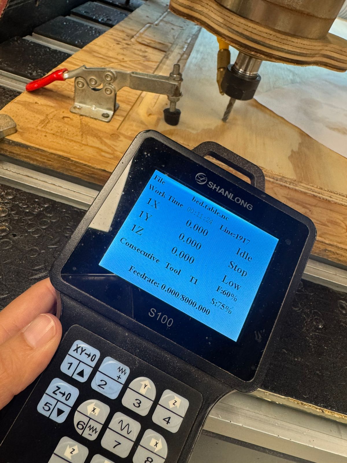
- Setting all origins in the machine (X, Y & Z)
- Realizing the size of my material and my design did not match = Correcting the design
- Rescaling some dimensions and moving shapes around to make them fit
- Also correcting some steps in the process like the order of cuts and the depth of each pass
- Cutting until my material accidentally moved
- Continued with the rest (another code had to be equally generated)
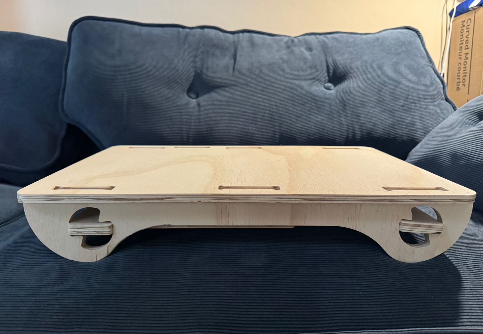
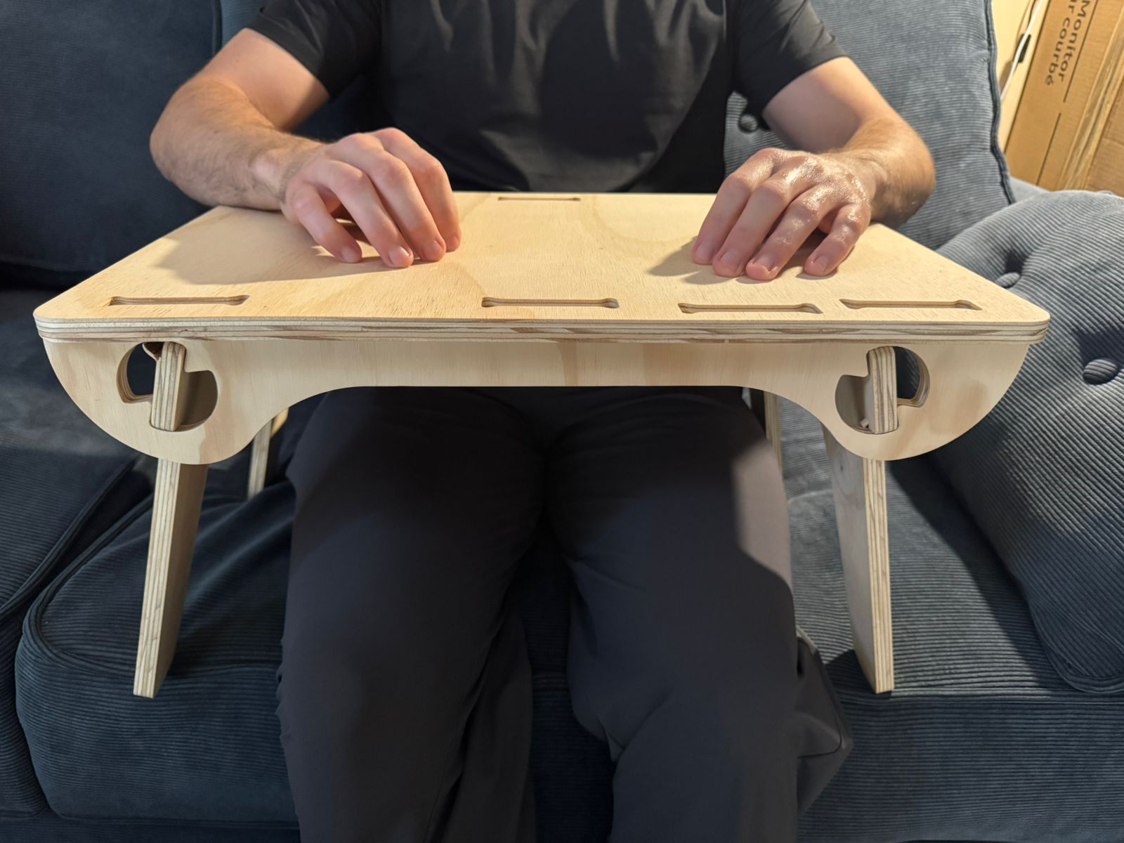
- Post.processing = Sanding and assembling
The final outcome:
 Download all files