Week 11: Networking and Communications
Group assignment
Week 11Introduction
This week, I will be working on establishing MQTT communication between three different boards, two of which are custom-made PCBs. One of these PCBs was designed and fabricated by a colleague at the fab, making the project even more collaborative and interesting.
The main goal is to use MQTT as the communication protocol to allow the boards to exchange data efficiently and reliably. Through this setup, we plan to control an OLED display and several NeoPixels remotely, enabling the devices to react to transmitted messages in real time.
This project will also help me gain more experience with wireless communication systems, embedded programming, and device synchronization. In addition, working with multiple interconnected boards will improve my understanding of how distributed electronic systems operate together within a single project.
Communications
MQTT protocol
For communication, the MQTT protocol will be used, as it is lightweight, efficient, and ideal for systems with multiple
devices connected to the same broker. One of its main advantages is the publish/subscribe model, which allows three or
more devices to communicate without needing direct connections between them. This reduces complexity, improves scalability,
and enables real-time bidirectional communication.
The broker used will be MQTTX, as it provides an online client that simplifies testing and debugging connections without requiring
local installation. This makes it easier to visualize topics, messages, and device interactions in real time.
MQTT Configuration (MQTTX)
General Settings
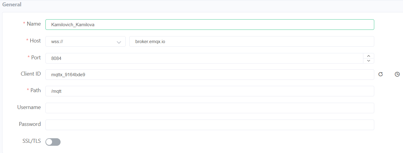
Name
Identifier of the device within the MQTT client. It helps distinguish between multiple connected devices.
In this case: Kamilovich_Kamilova
Host
Address of the MQTT broker. In this case, it uses a secure WebSocket connection (WSS) to communicate over the internet.
wss://broker.emqx.io
Port
Communication port used for secure WebSocket connections.
Port 8084 is commonly used for MQTT over WSS.
Client ID
Unique identifier for each device connecting to the broker. It must be different for every client to avoid conflicts.
In this case: mqttx_9164bde9
Path
Endpoint used for WebSocket communication with the broker.
/mqtt
SSL/TLS
Enables encrypted communication, improving security when sending data over the internet.
MQTT Configuration (MQTTX)
Advanced Settings
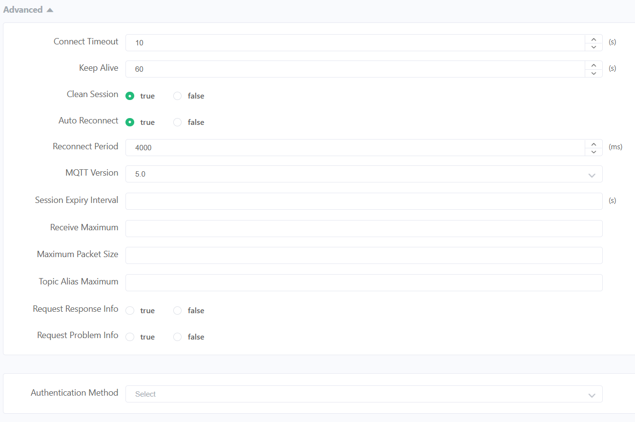
Connect Timeout
Maximum time the client waits to establish a connection before failing.
10 s
Keep Alive
Time interval in which the client sends a signal to maintain the connection active.
60 s
Clean Session
If enabled, the broker does not store previous session data when the client reconnects.
Auto Reconnect
Allows the client to automatically reconnect if the connection is lost.
Reconnect Period
Time between reconnection attempts.
4000 ms
MQTT Version
Protocol version used. Version 5.0 includes improved features like properties and better error handling.
5.0
MQTT Configuration (MQTTX)
Last Will and Testament
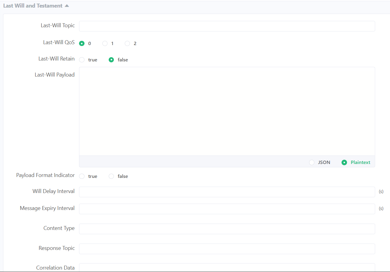
QoS (Quality of Service)
Defines the reliability level of message delivery between sender and receiver in MQTT. It determines how many times a message is sent and if confirmation is required.
QoS 0"At most once" delivery. The message is sent only one time with no confirmation. It is the fastest method but messages can be lost.
QoS 1"At least once" delivery. The message is guaranteed to arrive, but it may be received more than once due to retransmissions.
QoS 2"Exactly once" delivery. Ensures the message arrives only one time using a handshake process. It is the most reliable but also the slowest.
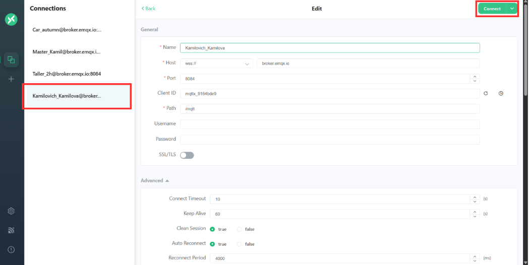
MQTTX Connection and Subscriptions
Once the client information is configured, you can click the “Connect” button to create the connection.
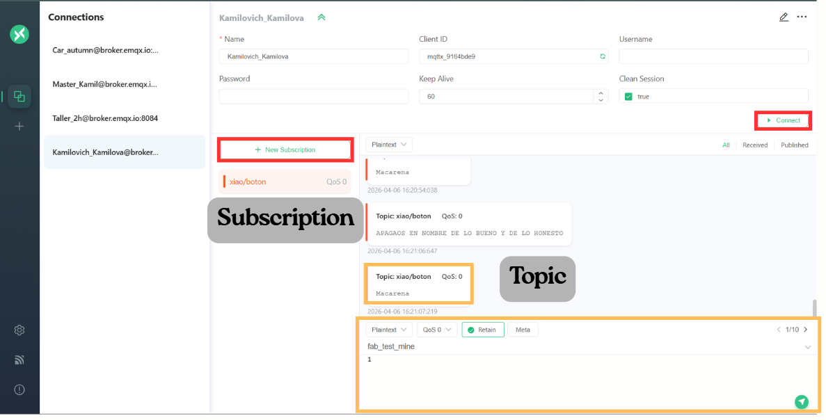
Subscriptions
A subscription is the process by which a client tells the broker that it wants to receive messages from a specific topic.In MQTT, communication works using a publish/subscribe model, meaning:
- Devices do not talk directly to each other
- They communicate through topics managed by the broker
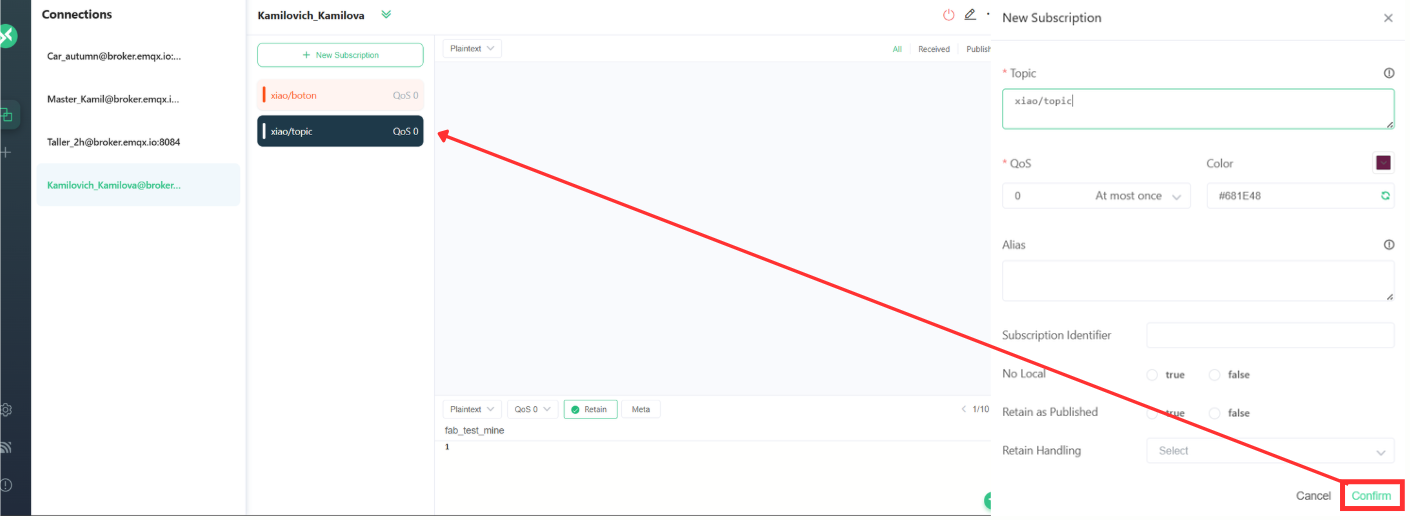
- Make sure the client is connected to the broker
- Click on “New Subscription”
- Assign a topic and customize the preferences
- Click on confirm.
Main
Main
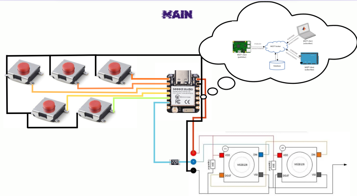
This image is from Derek Rodriguez Fab Site. Take a look at it Week 11
The diagram shows the wiring of the system powered by the 5V output of the XIAO ESP32-C6. This voltage rail supplies power to the NeoPixels, while all GND connections are tied directly to the XIAO’s GND, creating a common ground that ensures stable operation and proper signal reference across the system.
Additionally, the system includes five push buttons used for input commands. These buttons are connected directly to the XIAO pins from D0 to D4 and use the internal pull-up resistor configuration, meaning each pin reads HIGH by default and switches to LOW when the button is pressed.
From pin D5, a 220 Ω resistor is placed in series with the data line that connects to the input (DIN) of the NeoPixels. This resistor helps protect the data line from voltage spikes and improves signal integrity. The NeoPixels are connected in series, where the data flows from the first LED to the next (DOUT to DIN), allowing the microcontroller to control all LEDs through a single data pin.
XIAO ESP32-C6 Board
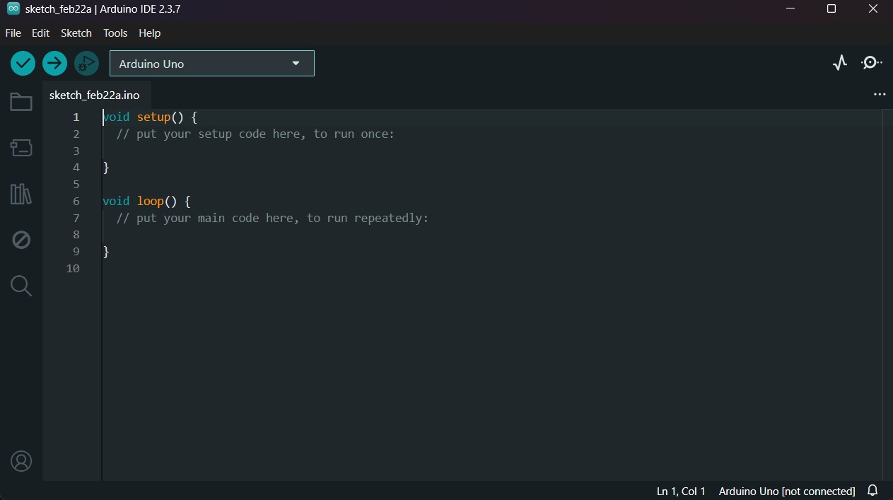
1.First, we have to create a sketch in Arduino IDE.
XIAO ESP32-C6 Board
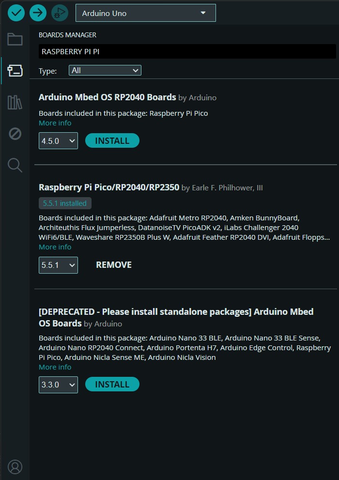
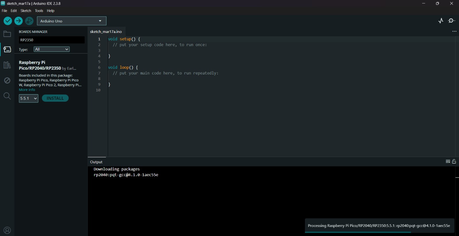
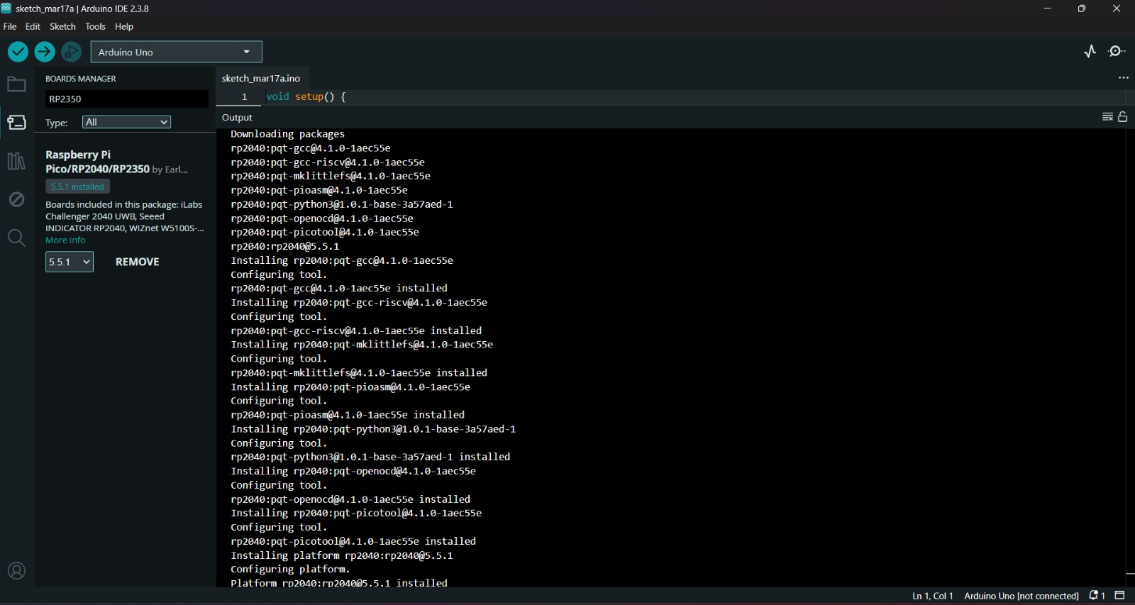
2.Then, we have go to the board manager and write XIAO. After doing that, a library will appear, its name is Raspberry Pi Pico/RP2040/RP2350 by Earle F. Philhower, III, we must install it.
Uploading
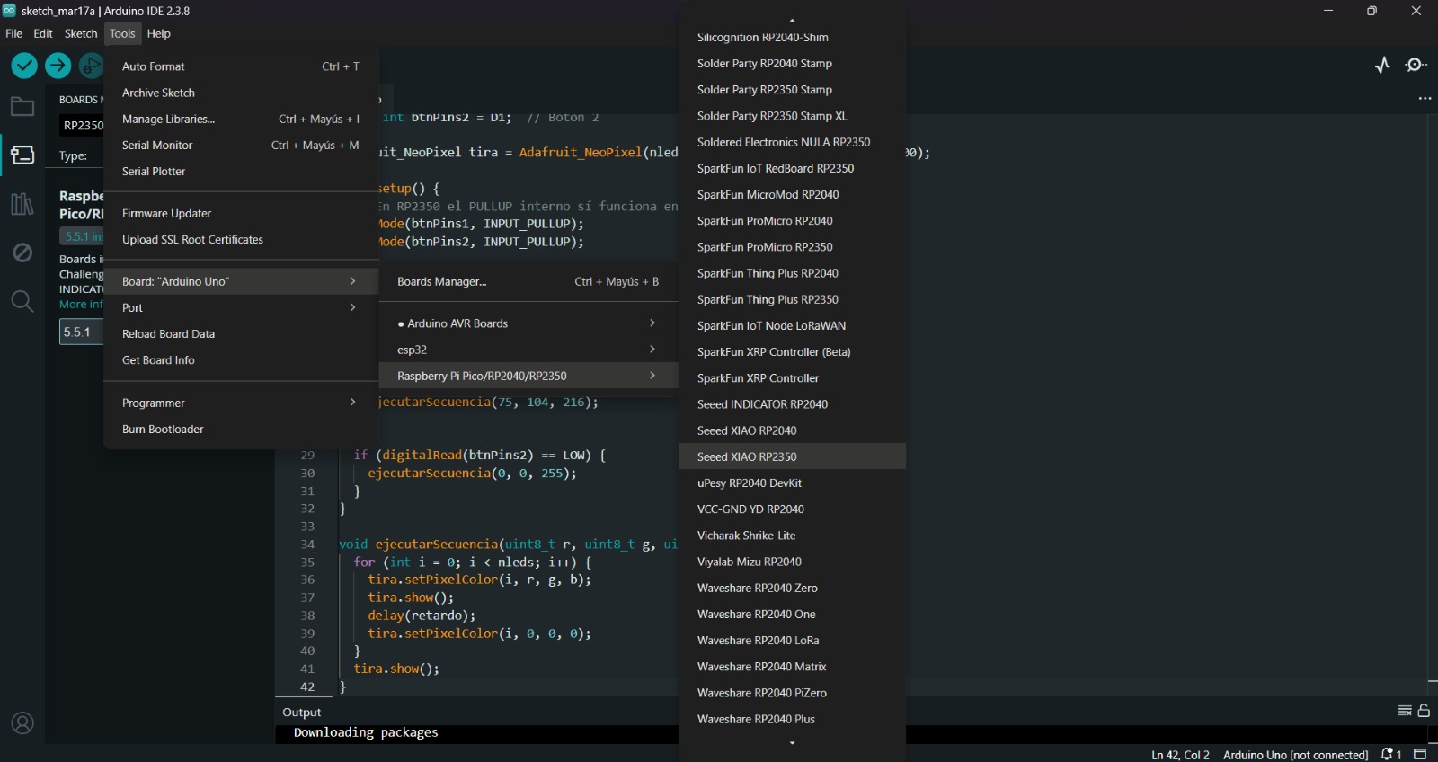
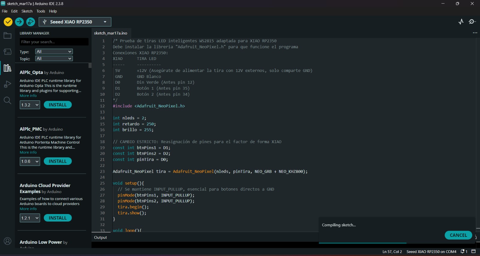
3.After installing the XIAO ESP32-C6 Board, we must click on the tab that says select board and write Seeed XIAO ESP32-C6, then select the PORT where our microcontroller is connected and upload the information. We can also click Tools, then Board and then the library Raspberry Pi Pico/RP2040/RP2350 by Earle F. Philhower, III and there look for the XIAO. Both ways will let us set our board as a XIAO.
4.Before uploading our code to the microcontroller we should use the verify tool, that compiles the code before uploading it in order to detect mistakes or problems. The verify tool is the one in the top with the check.
5.Finally, to upload our code we must click the upload tool, that is the one with the arrow pointing to the right. If our code is right, it shall compile. To get the , we must click on Tools in the top menu and select Serial Monitor.
XIAO ESP32-C6
Diagram of connections
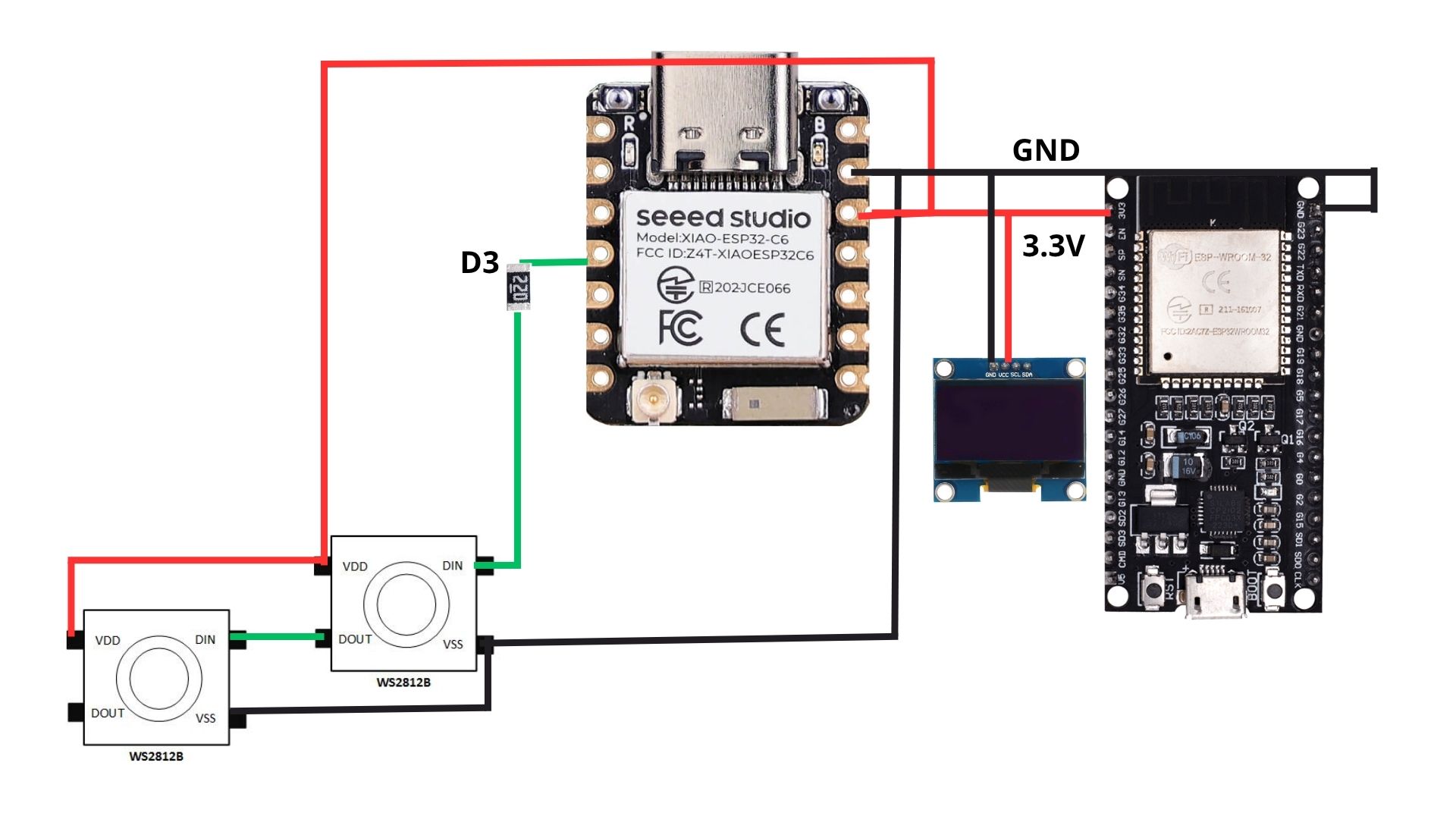
This diagram represents the wiring of the system powered by a Seeed Studio XIAO ESP32-C6. The red 3.3V line and black GND line form a common power rail that distributes energy to two WS2812B NeoPixels, an OLED display, and a ESP32-WROOM-32 dev module. The green signal line originates from pin D3, passing through a 220Ω resistor (used to protect the data pin from voltage spikes) before reaching the DIN port of the first NeoPixel; the signal then chains from DOUT to the next pixel's DIN. This setup allows the XIAO to act as the controller of the ESP32 and the Neopixels, managing both local visual feedback.
Programming
To code, I used ARDUINO IDE. ARDUINO IDE is a free, open-source application for Windows, macOS, and Linux, used to write, compile, and upload code to Arduino boards. It provides a text editor, toolbar, and serial monitor, supporting C/C++ to create ".ino" sketch files for controlling microcontrollers.

XIAO ESP32-C6 Board
1. First, we have to create a sketch in Arduino IDE.
XIAO ESP32-C6 Board
2. Then, we have go to the board manager and write XIAO. After doing that, a library will appear, its name is Raspberry Pi Pico/RP2040/RP2350 by Earle F. Philhower, III, we must install it.
Uploading
3. After installing the XIAO ESP32-C6 Board, we must click on the tab that says select board and write Seeed XIAO ESP32-C6, then select the PORT where our microcontroller is connected and upload the information. We can also click Tools, then Board and then the library Raspberry Pi Pico/RP2040/RP2350 by Earle F. Philhower, III and there look for the XIAO. Both ways will let us set our board as a XIAO.
4. Before uploading our code to the microcontroller we should use the verify tool, that compiles the code before uploading it in order to detect mistakes or problems. The verify tool is the one in the top with the check.
5. Finally, to upload our code we must click the upload tool, that is the one with the arrow pointing to the right. If our code is right, it shall compile. To get the , we must click on Tools in the top menu and select Serial Monitor.
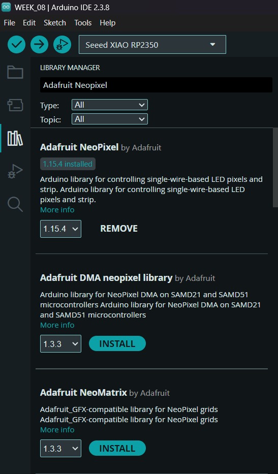
Neopixels Library
To set the neopixels, we first need to install the library in Arduino. For that we have to go to the Library Manager and write Adafruit Neopixel, then intall the library named like that.
ESP32 WROOM 32
Diagram of connections
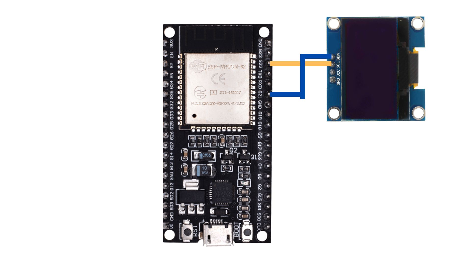
This diagram shows the I2C communication setup between an ESP32-WROOM-32 development board and an OLED display. The blue line connects the SDA (Serial Data) pin of the OLED to GPIO 21 on the ESP32, while the yellow line connects the SCL (Serial Clock) pin to GPIO 22. These two pins are the standard hardware I2C default for the ESP32, allowing the microcontroller to send graphical data and text to the screen using a synchronous serial protocol.
Programming
To code, I used ARDUINO IDE. ARDUINO IDE is a free, open-source application for Windows, macOS, and Linux, used to write, compile, and upload code to Arduino boards. It provides a text editor, toolbar, and serial monitor, supporting C/C++ to create ".ino" sketch files for controlling microcontrollers.
ESP32
1. First, we have to create a sketch in Arduino IDE.
ESP32
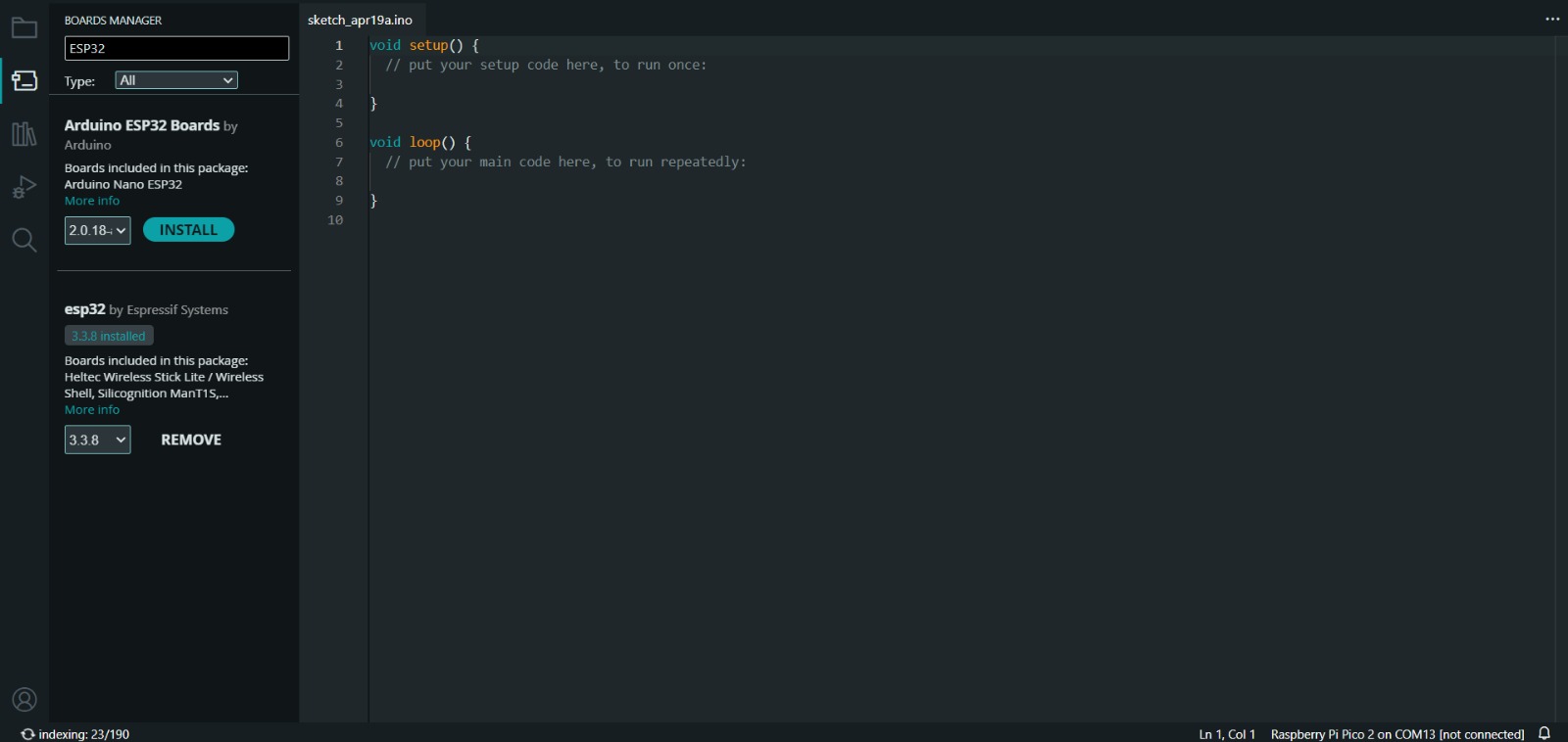
2. Then, we have go to the board manager and write ESP32. After doing that, a library will appear, its name is esp32 by Espressif Systems, we must install it.
Uploading
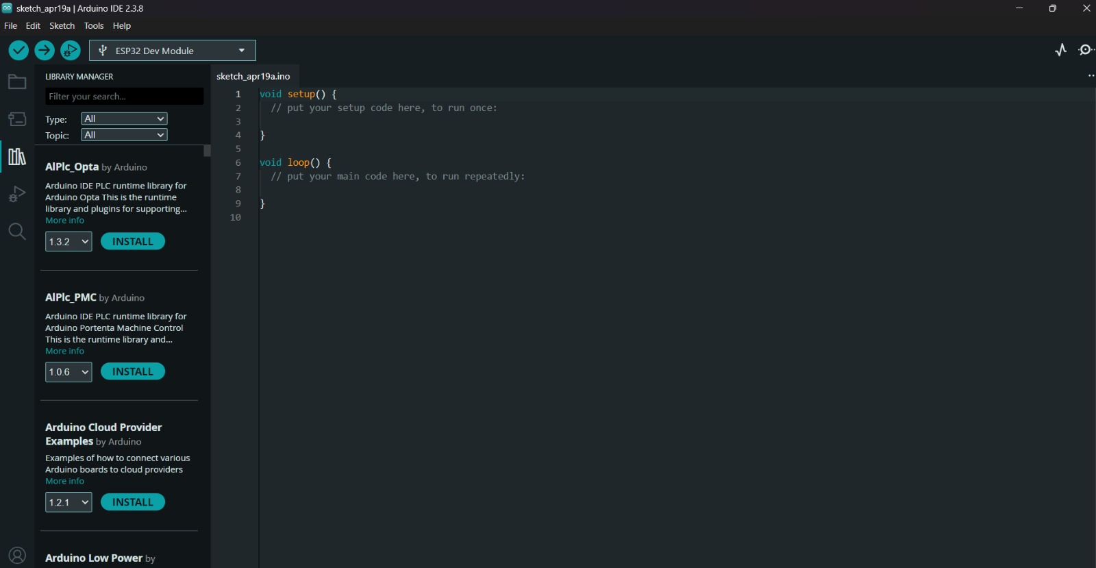
3. After installing the ESP32 Board, we must click on the tab that says select board and write ESP32 Dev Module, then select the PORT where our microcontroller is connected and upload the information.
4. Before uploading our code to the microcontroller we should use the verify tool, that compiles the code before uploading it in order to detect mistakes or problems. The verify tool is the one in the top with the check.
5. Finally, to upload our code we must click the upload tool, that is the one with the arrow pointing to the right. If our code is right, it shall compile. To get the , we must click on Tools in the top menu and select Serial Monitor.
Adafruit Library
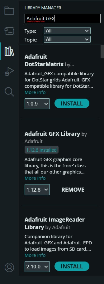
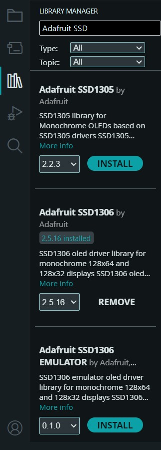
To set the OLED, we first need to install the library in Arduino. For that we have to go to the Library Manager and write Adafruit GFX and the Adafruit SSD1306, then intall the library named like that.
Results
Learning outcomes
This week, I learned a great deal about communication systems and how devices can exchange information with one another. One of the most important things I learned was how to establish communication between different boards using MQTT and a broker. Through this process, I gained a better understanding of how messages are transmitted, received, and managed within a network of connected devices.
I also continued working with an I2C OLED display, which helped me improve my understanding of communication protocols and device addressing. In addition, I kept experimenting with NeoPixels, learning more about how to control their lighting effects and synchronize them with incoming data.
Overall, this week helped me strengthen my knowledge of embedded systems, wireless communication, and hardware integration by combining multiple technologies into a single project.