Week 11: Networking and Communications
Before starting
In embedded systems, communication methods define how devices exchange information, either within a circuit (local communication) or across networks (remote communication). These methods can be classified into low-level signal-based communication and protocol-based communication, both of which enable structured interaction between a main device and one or more peripheral devices.Example
An example of how communications work can be seen in automation processes, where there is a server that hosts several systems such as SCADA. This system connects to the internet, then communicates through a gateway that distributes the data to different controllers (such as PLCs), which are responsible for executing routines based on inputs and outputs.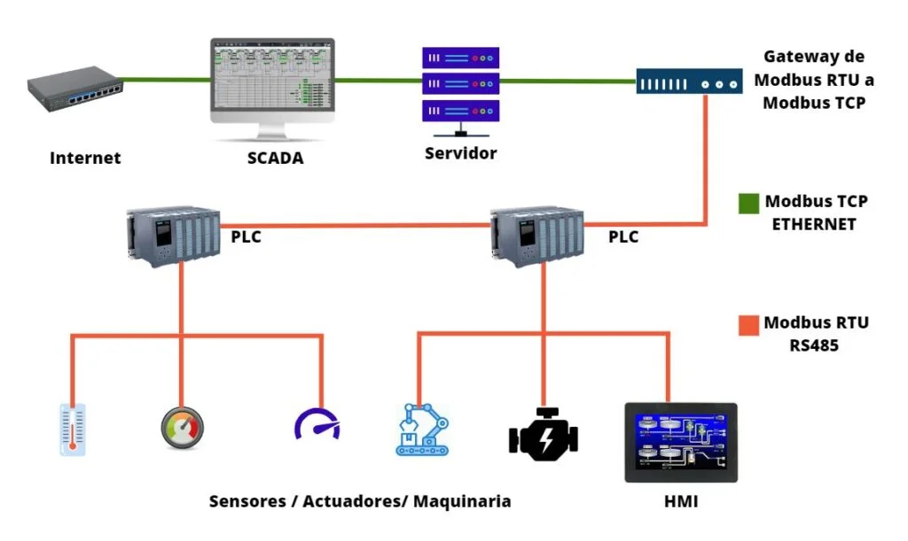
For further information about this topic, please consult this week’s group page.
Board
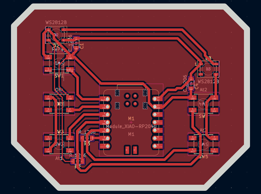
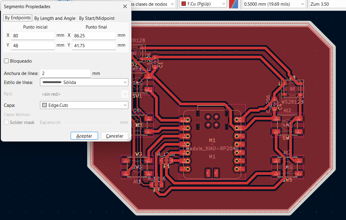
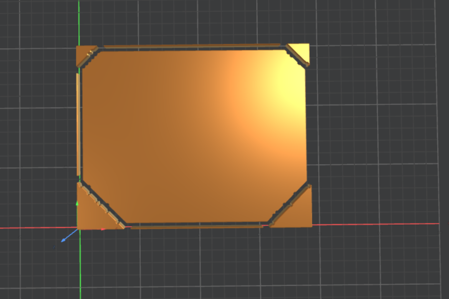
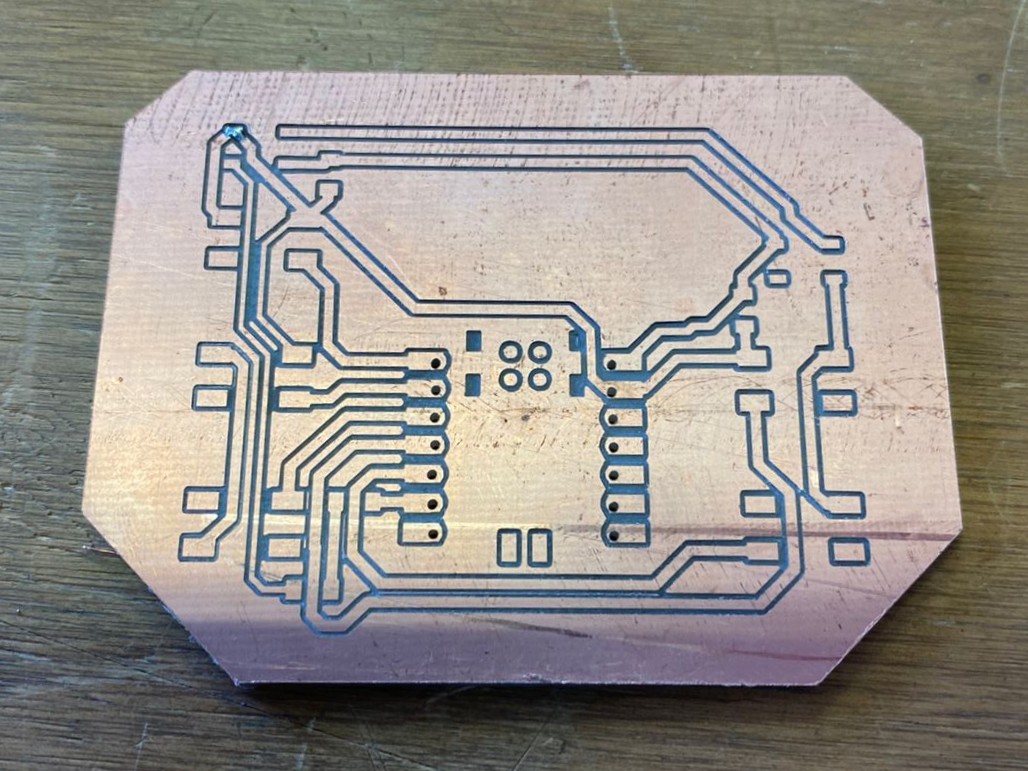
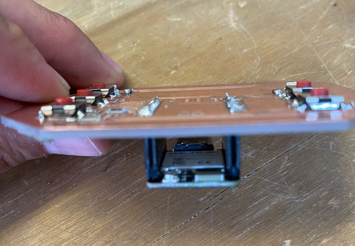
On the PCB design side, as mentioned before, this change makes it possible to reduce the overall board size and eliminates the need for a jumper wire to connect the external 5V line to the XIAO’s 5V pin, which was required in the previous prototype. This results in a cleaner and more reliable layout.
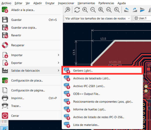
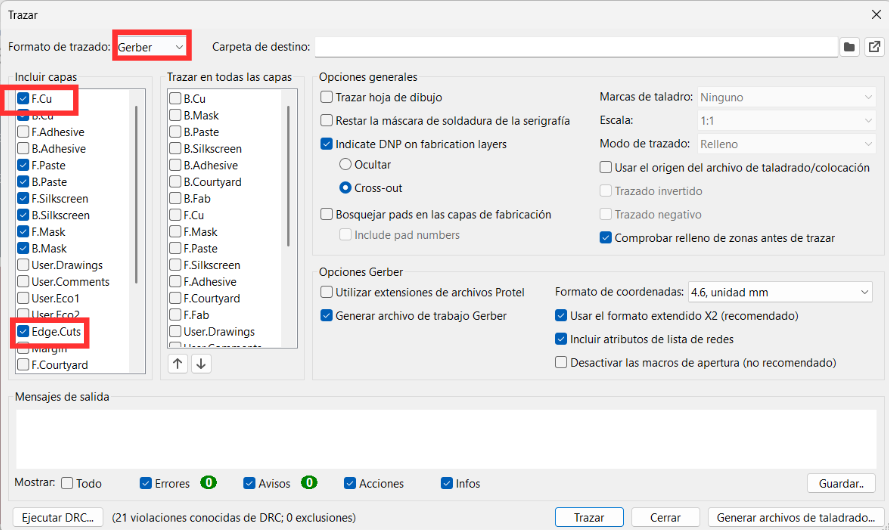
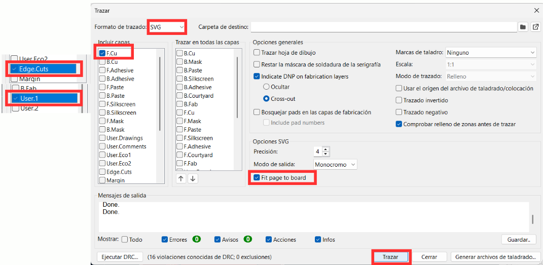
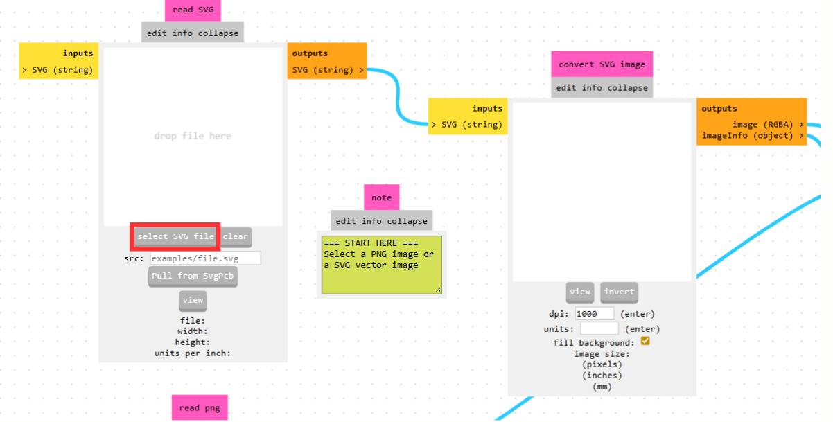
- Change the output format to SVG, since this format is compatible with the MonoFab workflow.
- Select each of the previously defined layers individually (such as traces, Edge.Cuts, and User layers).
- Enable the option “Fit page to board” to ensure the design scales correctly.
- Finally, click on “Plot” to generate the files.
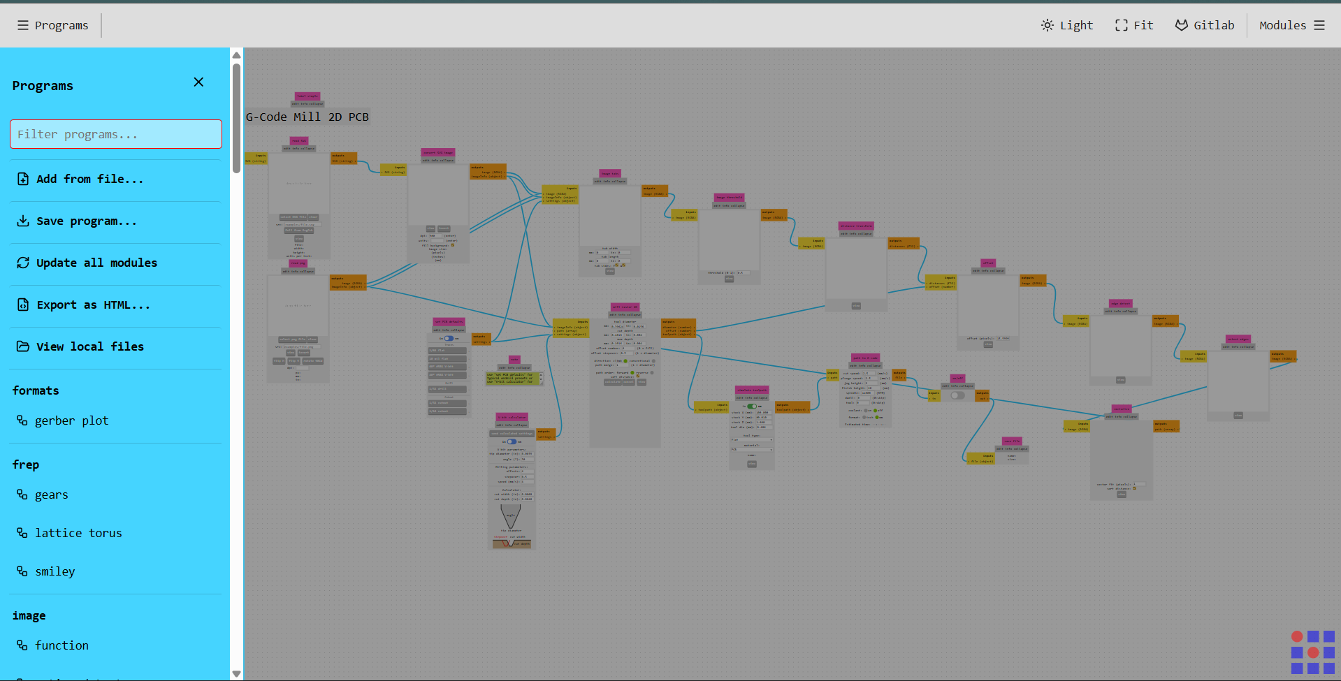
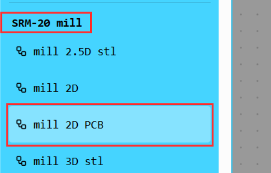
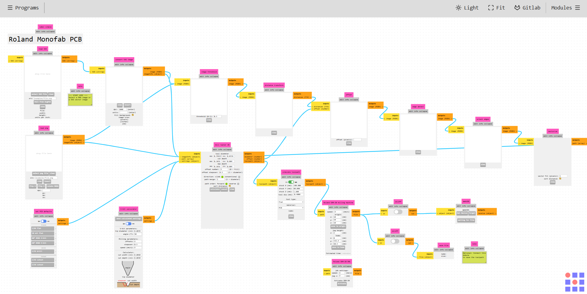
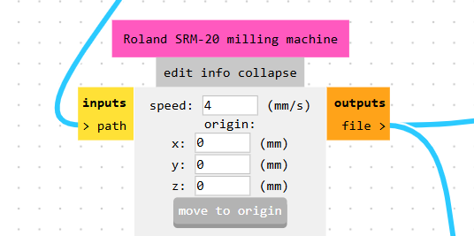
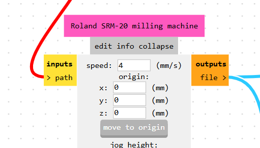
Within this platform, a wide variety of machines can be selected from the left-hand menu. In this case, the Roland SRM-20 milling machine was chosen under the “mill 2D PCB” option.
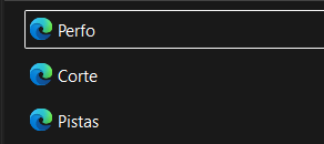
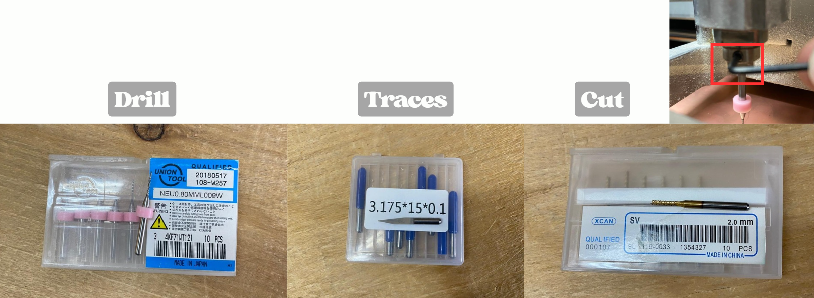
Drilling Process
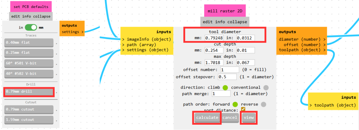
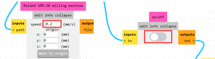
For drilling operations, a 0.79 mm drill bit is used. Before exporting the toolpath, it is necessary to adjust the feed rate in the Roland SRM-20 milling machine module to 0.2 mm/s, which helps prevent tool breakage due to excessive stress.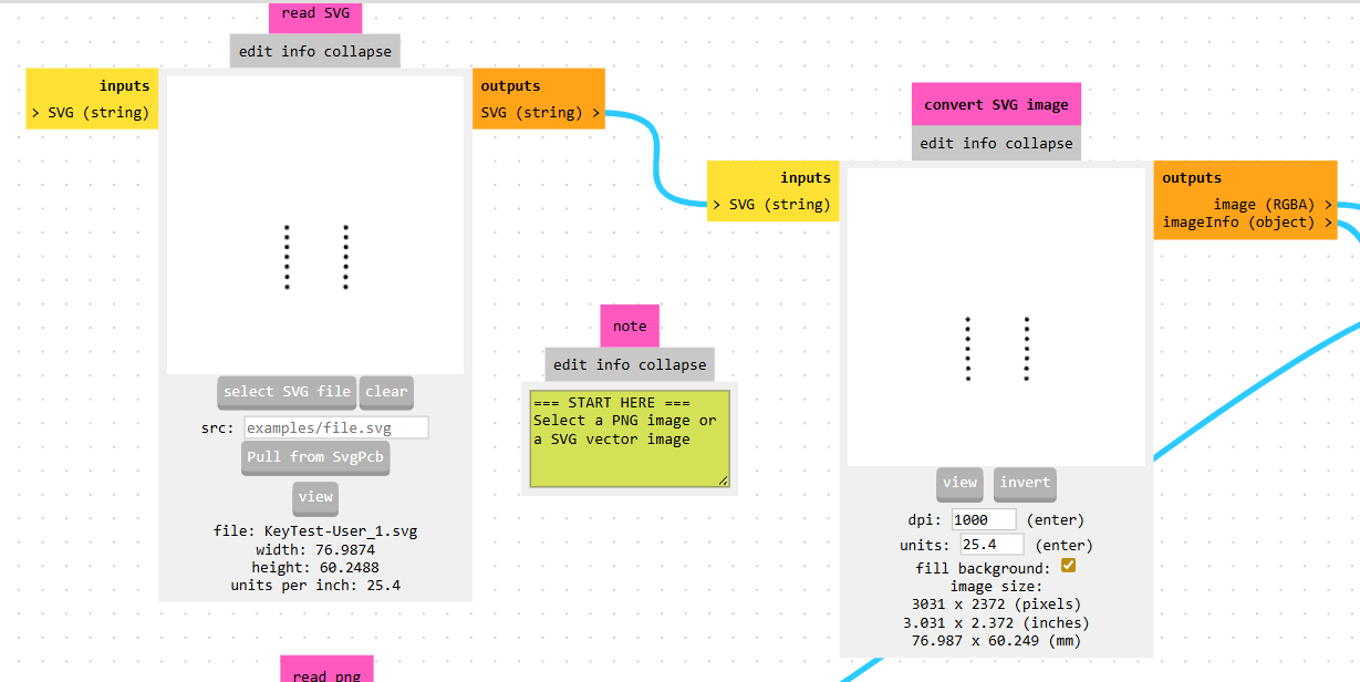
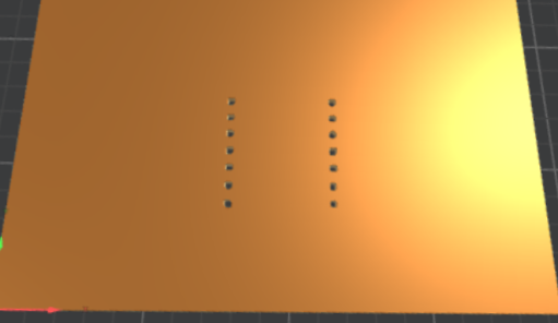
An important detail is that some holes, such as those for the transistor, may not appear. This occurs because the drill bit diameter is larger than the hole size defined in the design, making it impossible for the tool to reproduce those features accurately.
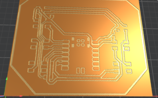
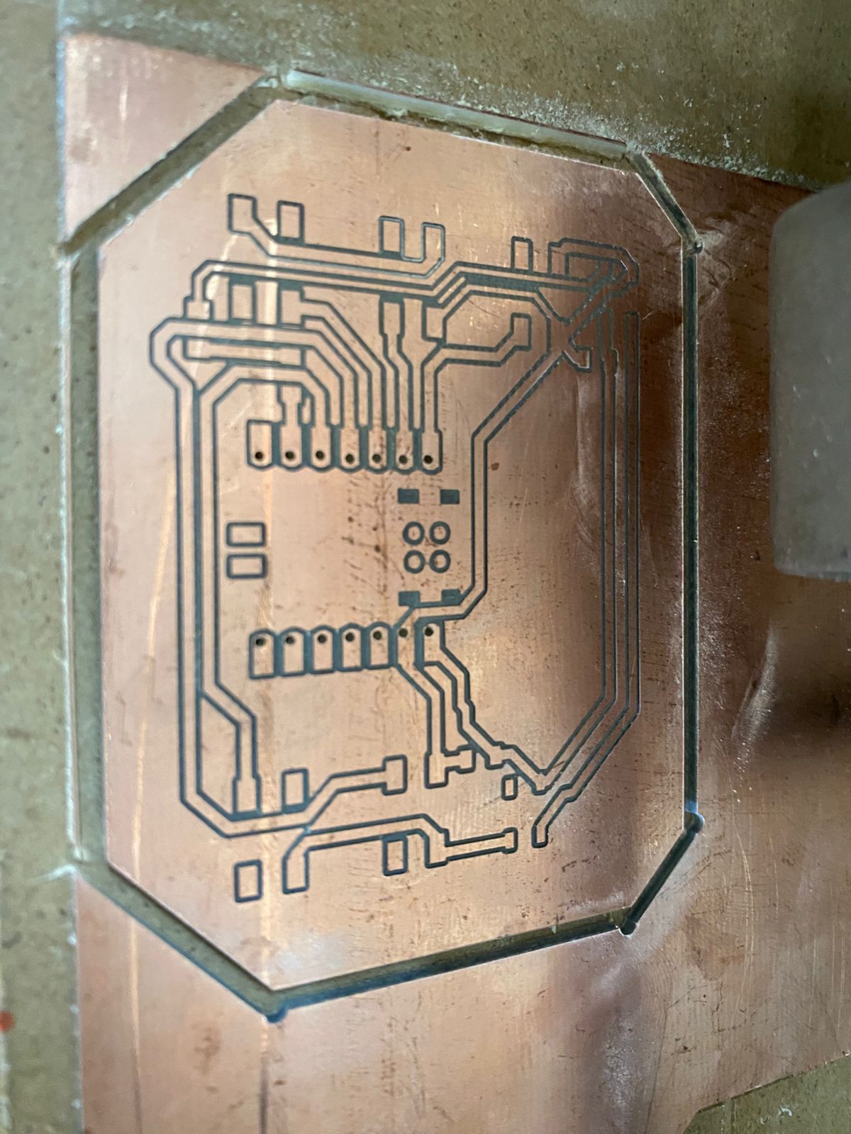
Traces Milling
The process for milling traces is similar, but with a key difference. When importing the SVG, the traces may appear in black, which indicates that they will be removed this is incorrect for PCB traces.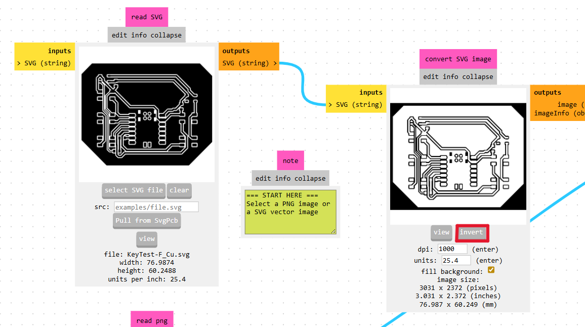
Board Outline
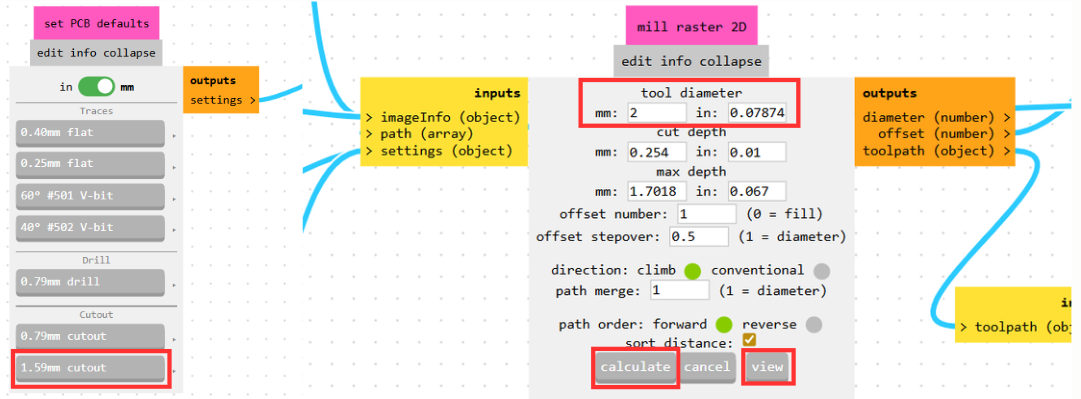
Finally, for cutting the board outline, a 1.59 mm cutout tool is used with a feed rate of 4 mm/s, maintaining the origin at (0,0,0).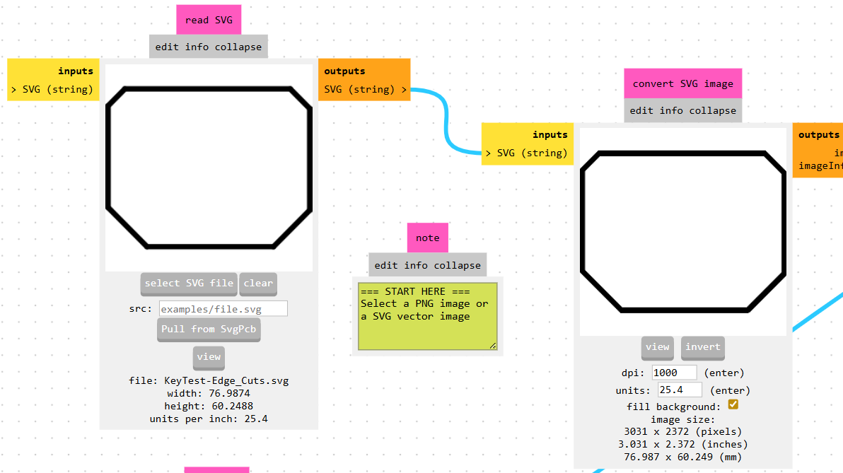
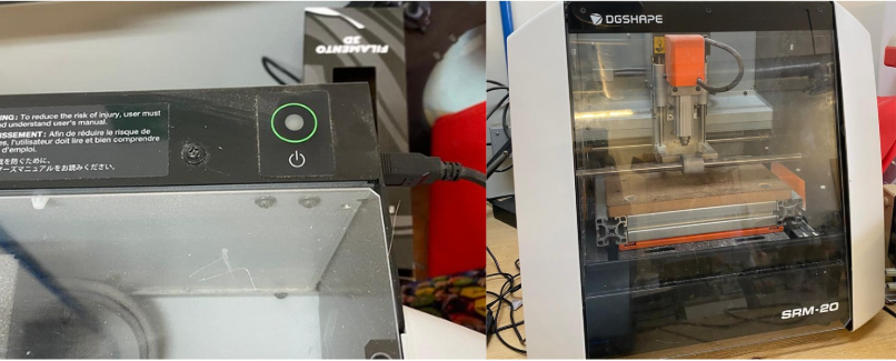
SRM-20 by DGSHAPE
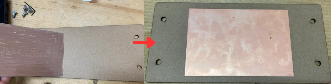
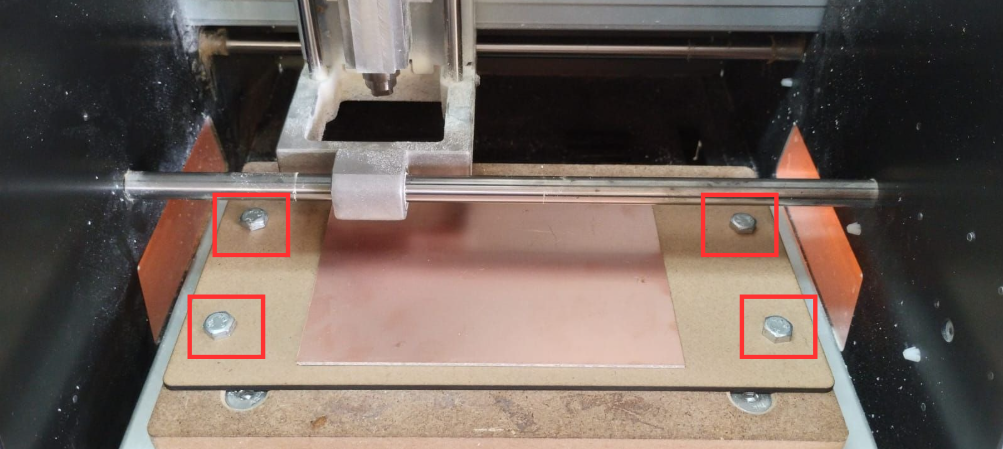
Moving on to the SRM-20 by DGSHAPE, the first step is to properly secure the PCB material onto the sacrificial bed. This is done using double-sided tape, ensuring the board is firmly attached. The sacrificial bed itself must be fixed to the MonoFab base using the provided screws or bolts to prevent any problem during machining.
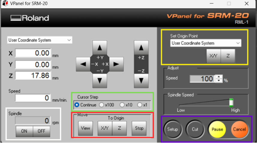
Set Origin Point:
This is used to define the reference position of the machine. The X/Y axes are set to establish the horizontal origin, and the Z axis is set separately to define the vertical starting point.
Move:
This option allows manual positioning of the toolhead to locate the origin or move to a specific point on the board.
Cursor Step:
Adjusts the step size or speed of manual movements, enabling fine or coarse positioning depending on the need.
Spindle:
Controls the rotation of the milling spindle. It is especially useful when setting the Z axis, as the tool can be carefully lowered without applying excessive force that could damage it.
Process Controls
These manage the execution of the machining jobs.
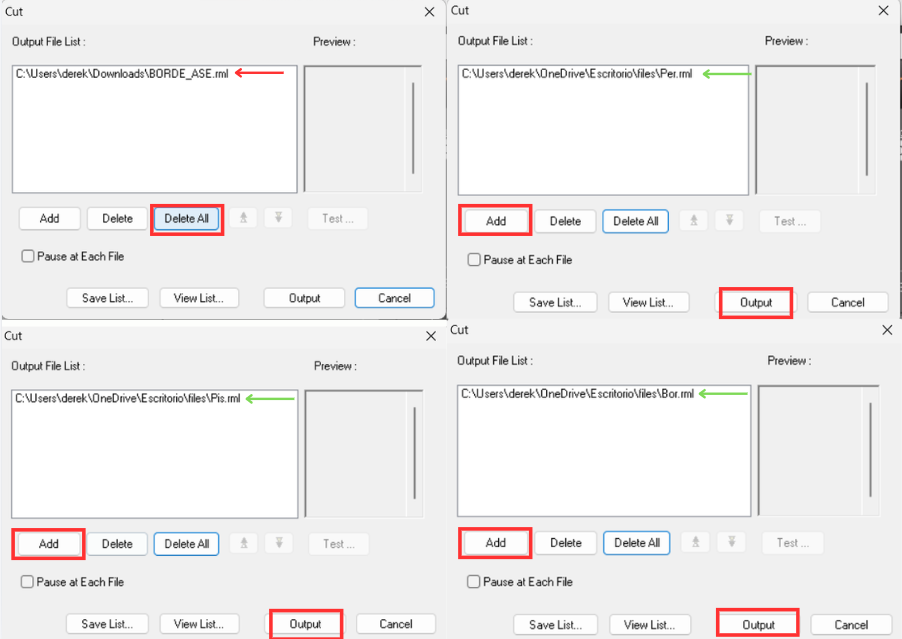
- Click “Delete All” to remove any previously loaded jobs.
- Click “Add” and select the .rml files generated earlier in MODS.
Drilling -> Traces -> Outline- If drilling is done after milling traces, it may damage or lift the copper tracks.
- If the outline is cut first, the board may move, ruining the remaining processes.
Tooling and Setup Considerations
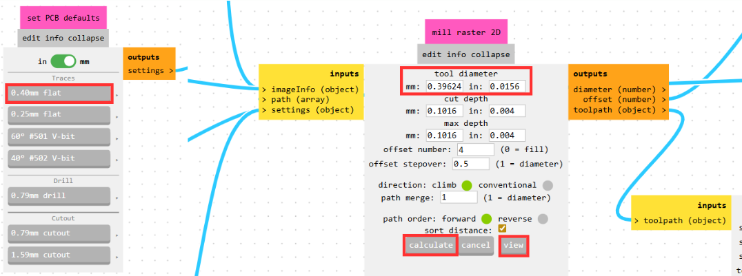
The tool dimensions used in MODS correspond to real milling bits:| Process | Tool Diameter |
|---|---|
| Drilling | 0.8 mm |
| Traces | rounded to 0.4 mm |
| Cutout | 2 mm |
Since each tool serves a different purpose, they must be changed between operations. This is why the files are executed separately and in a specific order.
Important:
Every time the tool is changed, the Z axis must be recalibrated, since the tool length may vary. Failing to do this can result in improper cutting depth or tool breakage.
- Securing the PCB material to the bed.
- Setting the X, Y, and Z origin points.
- Loading the .rml files in the correct order.
- Running each process sequentially (drilling, traces, cutout).
- Changing tools and recalibrating Z between each step.
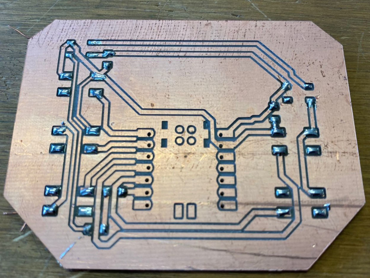
Solder
With the PCB already milled and cut, the next step is soldering. Since most of the components are SMD, it is necessary to pretin the pads before placing the components. This process consists of applying a small amount of solder to the pad by heating it with the soldering iron for a few seconds, and then feeding solder from the opposite side until it melts and forms a thin, even layer.Once the pad is pretinned, the component can be positioned and soldered by reheating the pad and allowing the solder to secure it in place.
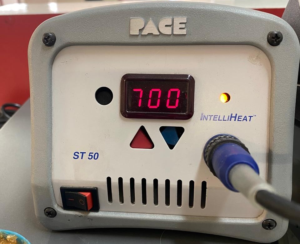
Soldering Temperatures
| Temperature (°F) | Application |
|---|---|
| 600–650°F | Delicate components, low thermal mass |
| 650–700°F | General SMD soldering (recommended range) |
| 700–750°F | Through-hole components or larger pads |
| 750°F+ | Heavy ground planes (use with caution) |
- Capacitors and resistors (smallest components)
- LEDs (SMD)
- Buttons and connectors
- Microcontroller (XIAO RP2040)
MQTT protocol
For communication, the MQTT protocol will be used, as it is lightweight, efficient, and ideal for systems with multiple devices connected to the same broker. One of its main advantages is the publish/subscribe model, which allows three or more devices to communicate without needing direct connections between them. This reduces complexity, improves scalability, and enables real-time bidirectional communication.The broker used will be MQTTX, as it provides an online client that simplifies testing and debugging connections without requiring local installation. This makes it easier to visualize topics, messages, and device interactions in real time.
MQTT Configuration (MQTTX)
General Settings
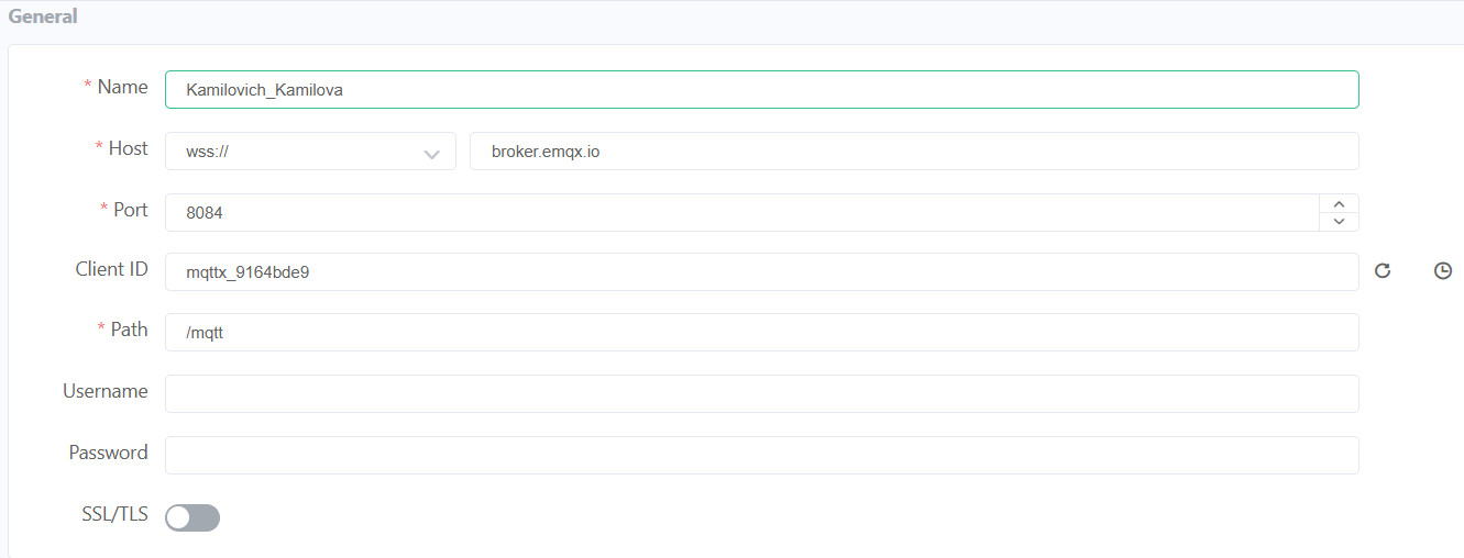
Name
Identifier of the device within the MQTT client. It helps distinguish between multiple connected devices.
In this case: Kamilovich_Kamilova
Host
Address of the MQTT broker. In this case, it uses a secure WebSocket connection (WSS) to communicate over the internet.
wss://broker.emqx.io
Port
Communication port used for secure WebSocket connections.
Port 8084 is commonly used for MQTT over WSS.
Client ID
Unique identifier for each device connecting to the broker. It must be different for every client to avoid conflicts.
In this case: mqttx_9164bde9
Path
Endpoint used for WebSocket communication with the broker.
/mqtt
SSL/TLS
Enables encrypted communication, improving security when sending data over the internet.
MQTT Configuration (MQTTX)
Advanced Settings
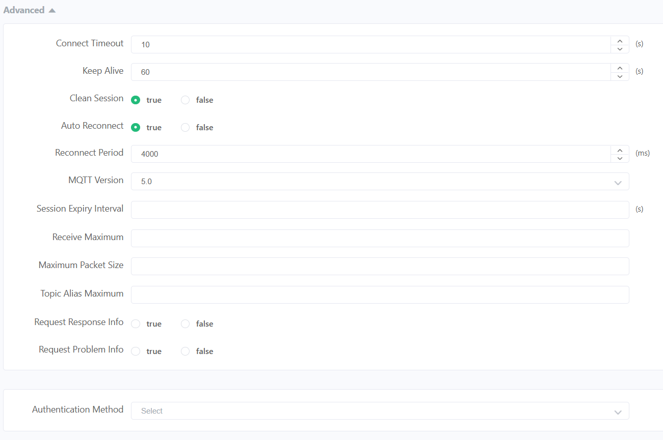
Connect Timeout
Maximum time the client waits to establish a connection before failing.
10 s
Keep Alive
Time interval in which the client sends a signal to maintain the connection active.
60 s
Clean Session
If enabled, the broker does not store previous session data when the client reconnects.
Auto Reconnect
Allows the client to automatically reconnect if the connection is lost.
Reconnect Period
Time between reconnection attempts.
4000 ms
MQTT Version
Protocol version used. Version 5.0 includes improved features like properties and better error handling.
5.0
MQTT Configuration (MQTTX)
Last Will and Testament
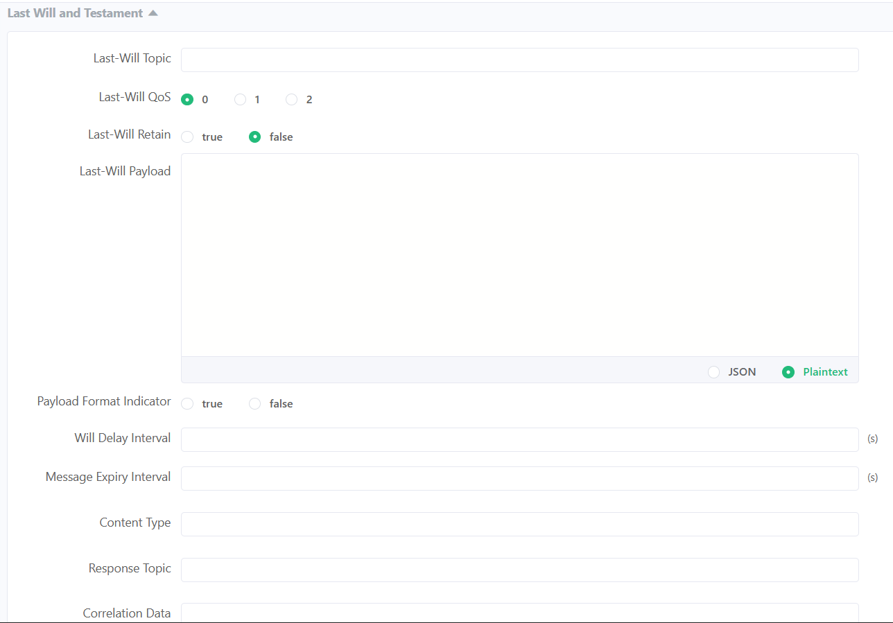
QoS (Quality of Service)
Defines the reliability level of message delivery between sender and receiver in MQTT. It determines how many times a message is sent and if confirmation is required.
QoS 0"At most once" delivery. The message is sent only one time with no confirmation. It is the fastest method but messages can be lost.
QoS 1"At least once" delivery. The message is guaranteed to arrive, but it may be received more than once due to retransmissions.
QoS 2"Exactly once" delivery. Ensures the message arrives only one time using a handshake process. It is the most reliable but also the slowest.
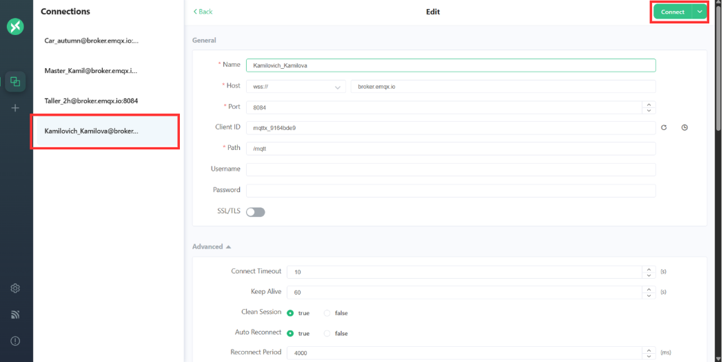
MQTTX Connection and Subscriptions
Once the client information is configured, you can click the “Connect” button to create the connection.
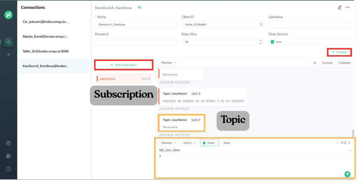
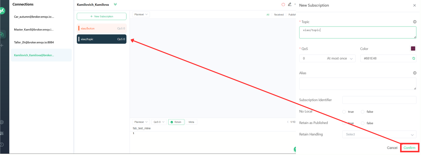
Subscriptions
A subscription is the process by which a client tells the broker that it wants to receive messages from a specific topic.In MQTT, communication works using a publish/subscribe model, meaning:
- Devices do not talk directly to each other
- They communicate through topics managed by the broker
- Make sure the client is connected to the broker
- Click on “New Subscription”
- Assign a topic and customize the preferences
- Click on confirm.
Code and connections
The connection diagram is divided into three boards: the one developed previously, which acts as the main controller, and two additional boards that function as peripherals, designed by another Fab Lab teammate.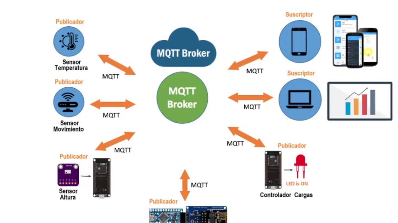
Additionally, this approach improves system flexibility and scalability, since multiple nodes can interact with each other through the same communication protocol, making it suitable for distributed systems such as IoT or MQTT-based networks.
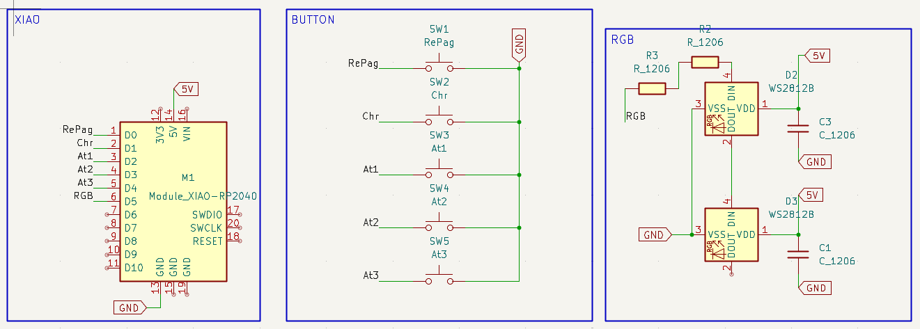
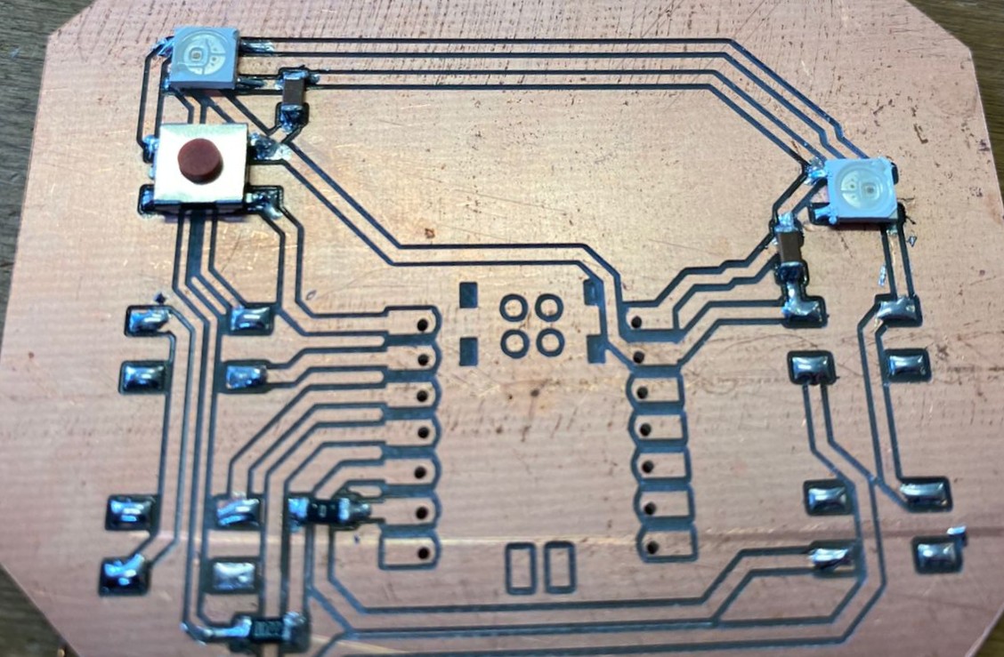
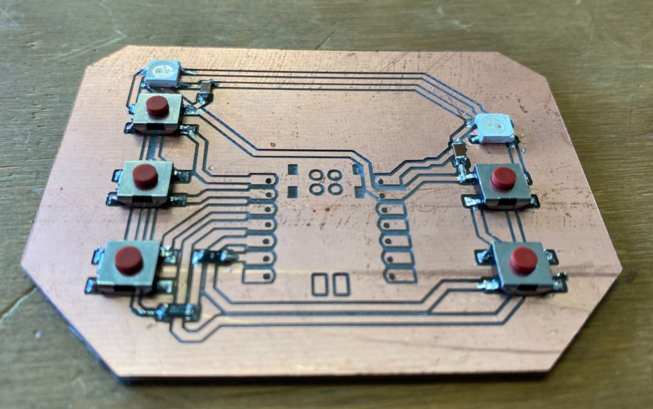
MAIN
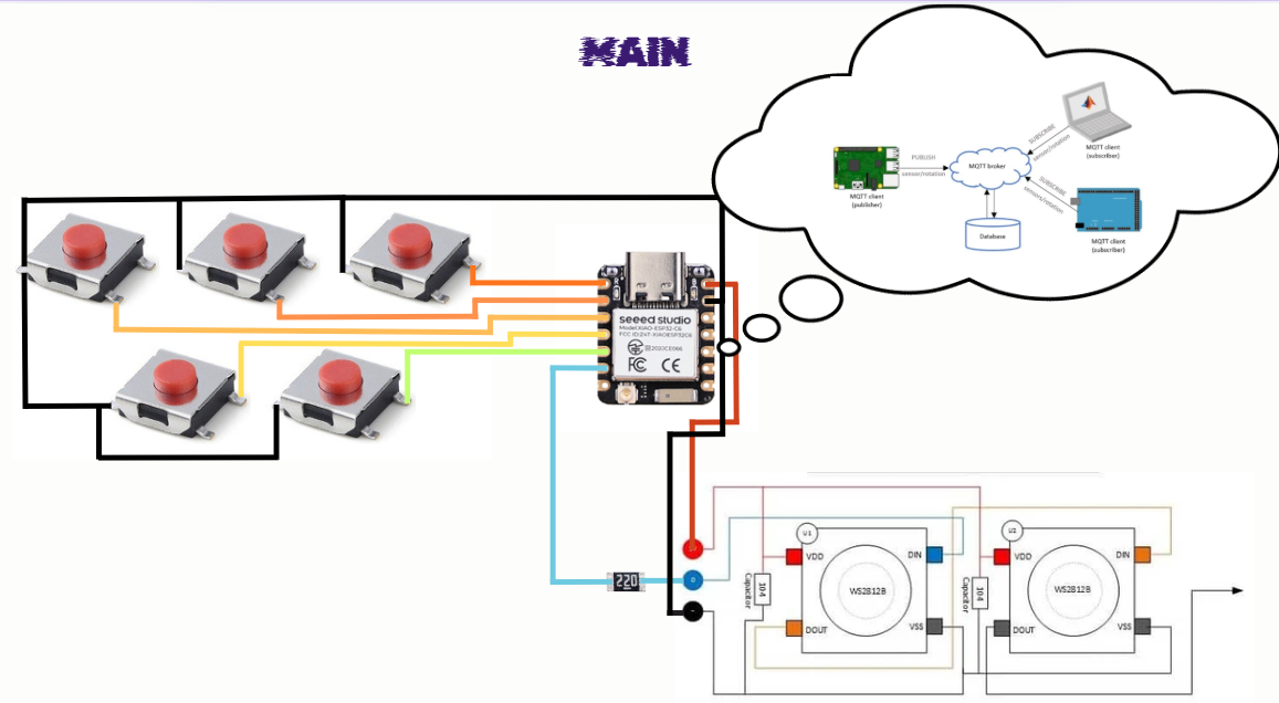
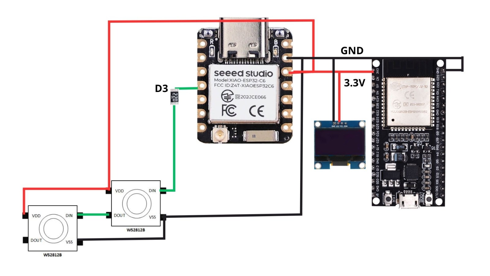
Additionally, the system includes five push buttons used for input commands. These buttons are connected directly to the XIAO pins from D0 to D4 and use the internal pull-up resistor configuration, meaning each pin reads HIGH by default and switches to LOW when the button is pressed.
From pin D5, a 220 Ω resistor is placed in series with the data line that connects to the input (DIN) of the NeoPixels. This resistor helps protect the data line from voltage spikes and improves signal integrity. The NeoPixels are connected in series, where the data flows from the first LED to the next (DOUT to DIN), allowing the microcontroller to control all LEDs through a single data pin.
XIAO ESP32-C6 Board
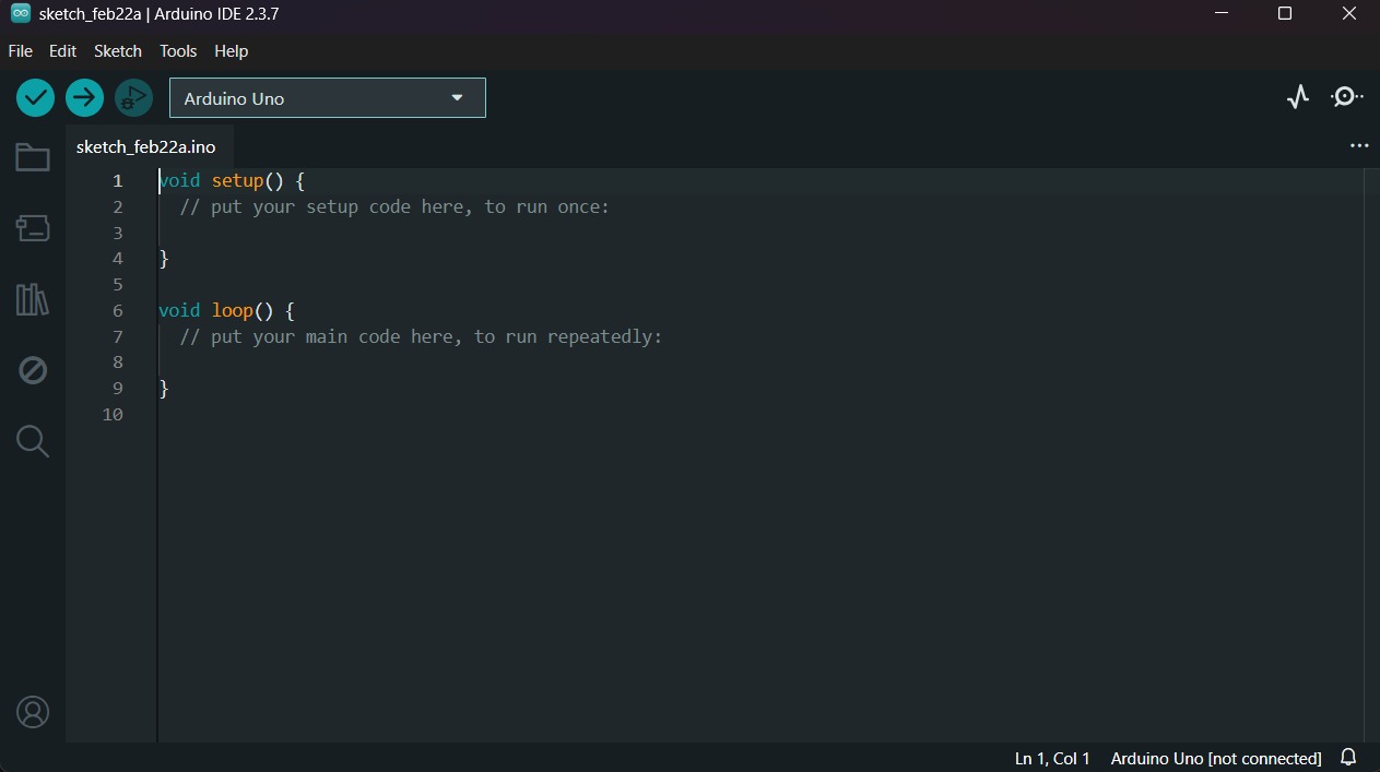
1.First, we have to create a sketch in Arduino IDE.
XIAO ESP32-C6 Board
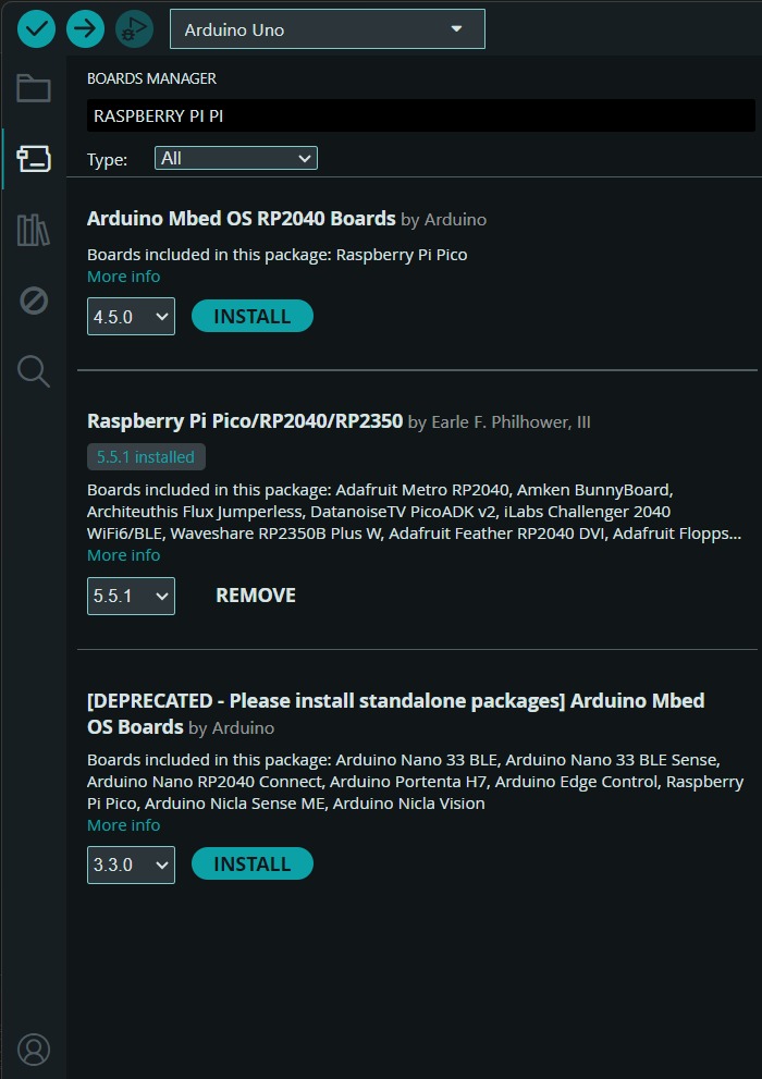
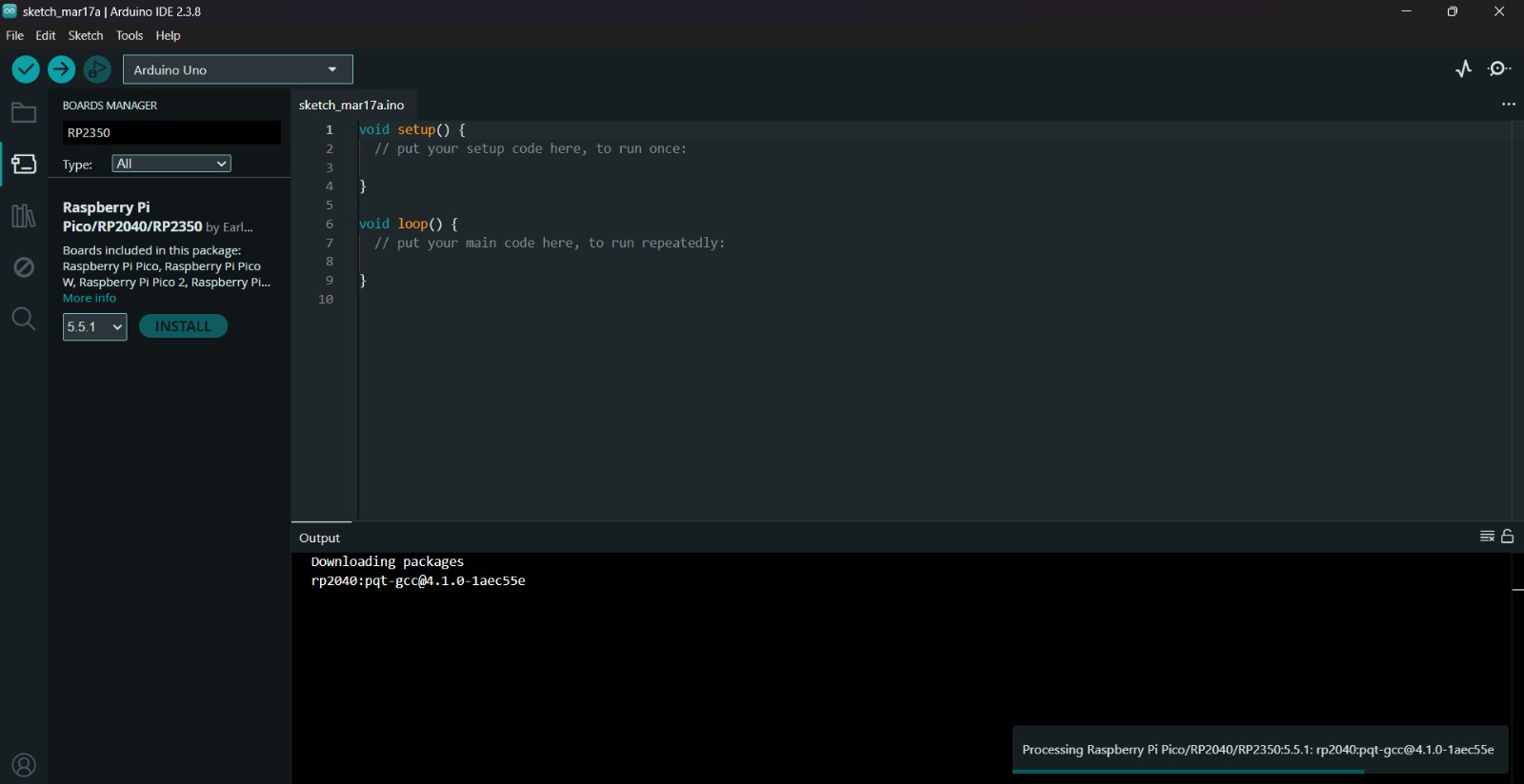
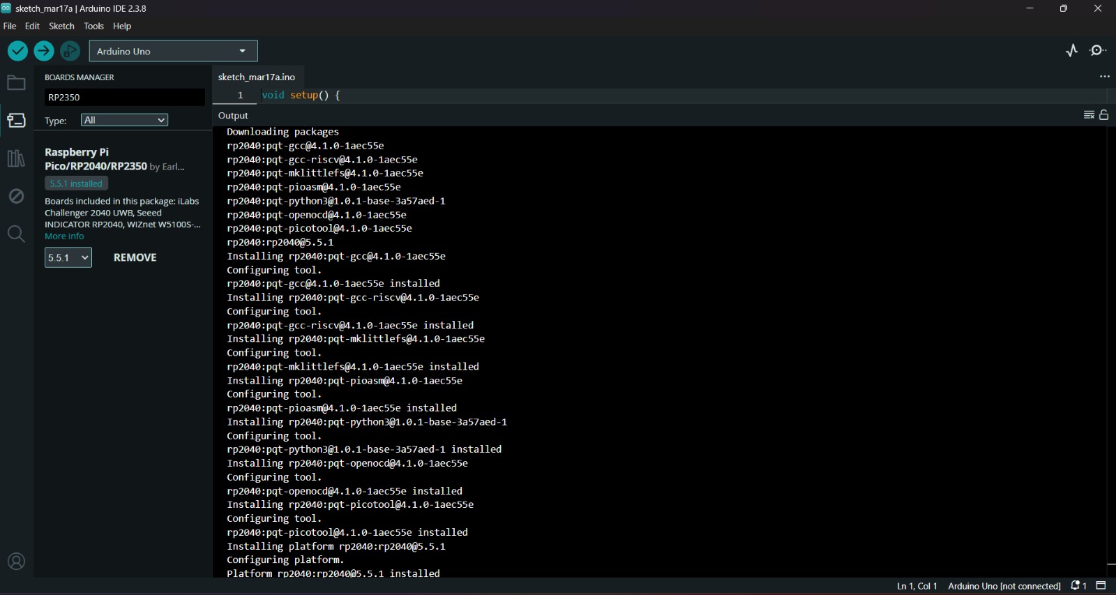
2.Then, we have go to the board manager and write XIAO. After doing that, a library will appear, its name is Raspberry Pi Pico/RP2040/RP2350 by Earle F. Philhower, III, we must install it.
Uploading
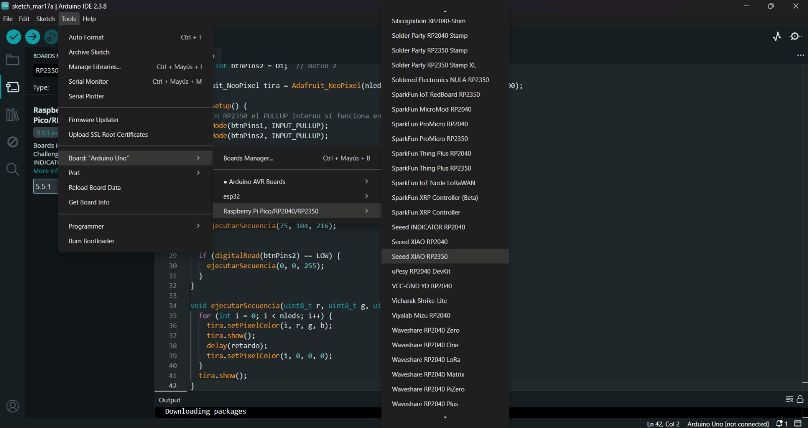
3.After installing the XIAO ESP32-C6 Board, we must click on the tab that says select board and write Seeed XIAO ESP32-C6, then select the PORT where our microcontroller is connected and upload the information. We can also click Tools, then Board and then the library Raspberry Pi Pico/RP2040/RP2350 by Earle F. Philhower, III and there look for the XIAO. Both ways will let us set our board as a XIAO.
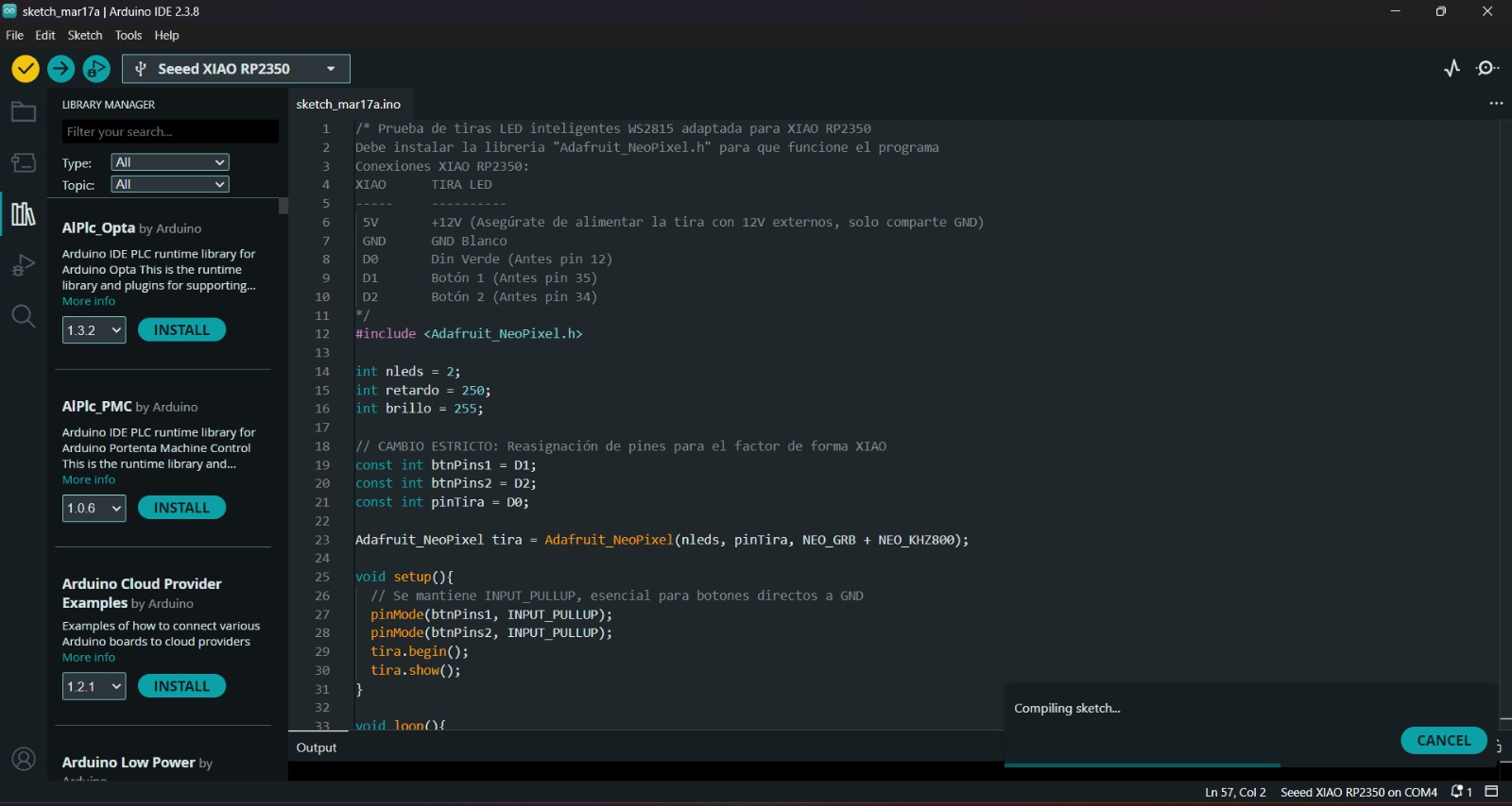
4.Before uploading our code to the microcontroller we should use the verify tool, that compiles the code before uploading it in order to detect mistakes or problems. The verify tool is the one in the top with the check.
5.Finally, to upload our code we must click the upload tool, that is the one with the arrow pointing to the right. If our code is right, it shall compile. To get the , we must click on Tools in the top menu and select Serial Monitor.
Peripheral
XIAO ESP32-C6 Board
1.First, we have to create a sketch in Arduino IDE.
XIAO ESP32-C6 Board
2.Then, we have go to the board manager and write XIAO. After doing that, a library will appear, its name is Raspberry Pi Pico/RP2040/RP2350 by Earle F. Philhower, III, we must install it.
Uploading
3.After installing the XIAO ESP32-C6 Board, we must click on the tab that says select board and write Seeed XIAO ESP32-C6, then select the PORT where our microcontroller is connected and upload the information. We can also click Tools, then Board and then the library Raspberry Pi Pico/RP2040/RP2350 by Earle F. Philhower, III and there look for the XIAO. Both ways will let us set our board as a XIAO.
4.Before uploading our code to the microcontroller we should use the verify tool, that compiles the code before uploading it in order to detect mistakes or problems. The verify tool is the one in the top with the check.
5.Finally, to upload our code we must click the upload tool, that is the one with the arrow pointing to the right. If our code is right, it shall compile. To get the , we must click on Tools in the top menu and select Serial Monitor.
Neopixels Library
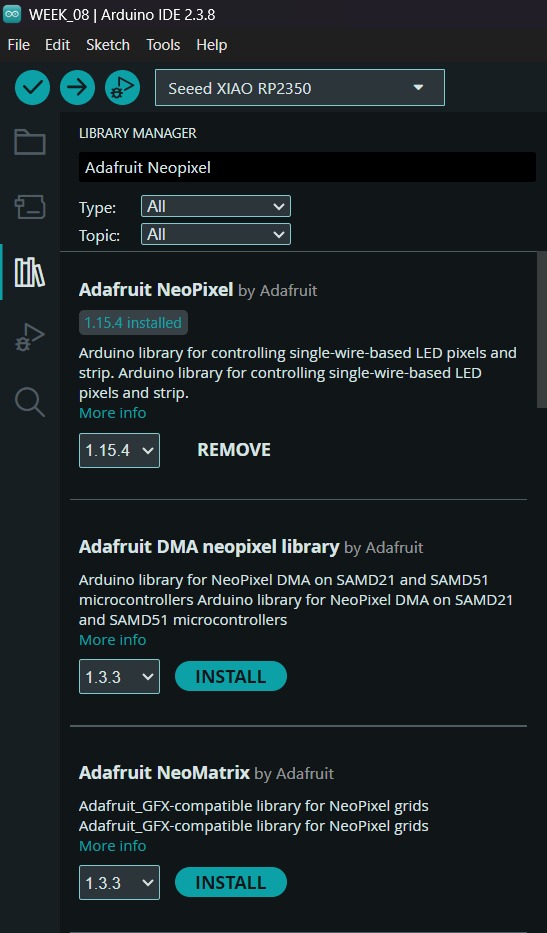
To set the neopixels, we first need to install the library in Arduino. For that we have to go to the Library Manager and write Adafruit Neopixel, then intall the library named like that.
Peripheral
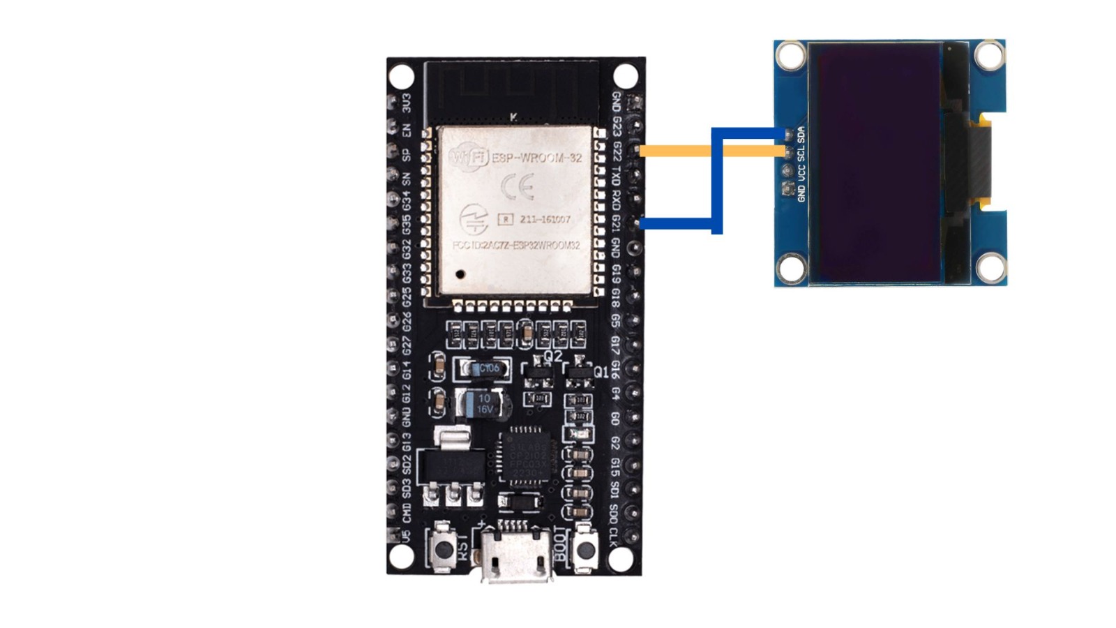
ESP32
1. First, we have to create a sketch in Arduino IDE.
ESP32
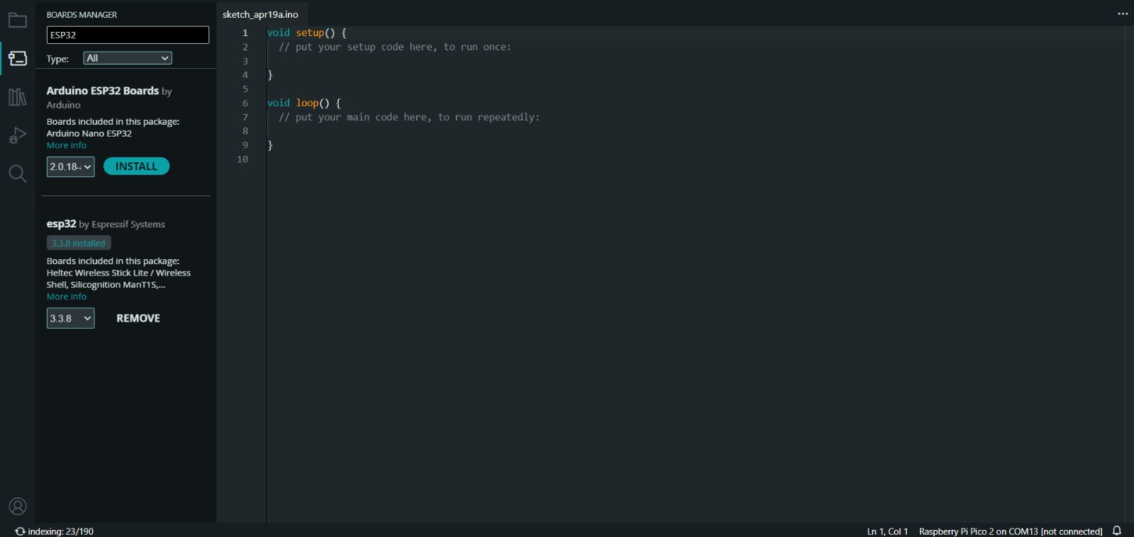
2. Then, we have go to the board manager and write ESP32. After doing that, a library will appear, its name is esp32 by Espressif Systems, we must install it.
Uploading
3. After installing the ESP32 Board, we must click on the tab that says select board and write ESP32 Dev Module, then select the PORT where our microcontroller is connected and upload the information.
4. Before uploading our code to the microcontroller we should use the verify tool, that compiles the code before uploading it in order to detect mistakes or problems. The verify tool is the one in the top with the check.
5. Finally, to upload our code we must click the upload tool, that is the one with the arrow pointing to the right. If our code is right, it shall compile. To get the , we must click on Tools in the top menu and select Serial Monitor.
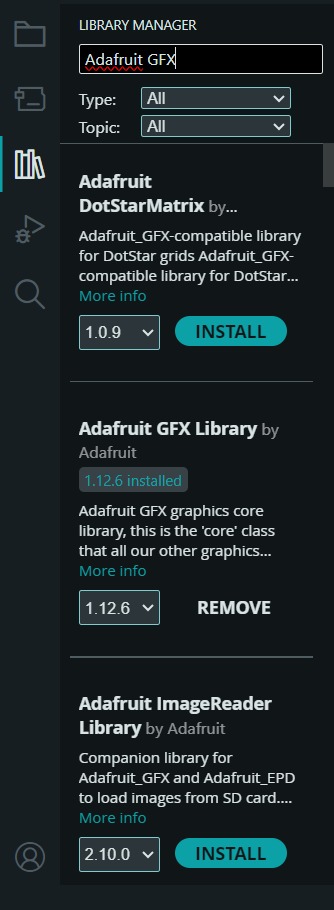
Adafruit Library
To set the OLED, we first need to install the library in Arduino. For that we have to go to the Library Manager and write Adafruit GFX and the Adafruit SSD1306, then intall the library named like that.