Week 2. Computer Aided Design
Summary
This week focused on learning how to use 2d and 3d programms vectorizing, drawing, and painting, as well as modeling pieces or objects. All of this with the aim of implementing it in our final project, or similarly, learning something new that might be useful to us in the future.
1. 2D softwares
2D softwares, such as Affinity or Inkscape, are primarily used to create and edit vector graphics, allowing users to work with images that retain their quality when scaled. One of their most important functions is image vectorization, as they allow users to transform raster images into editable shapes using precise lines and curves, facilitating their use in logos, illustrations, and graphic design. Furthermore, they incorporate drawing tools that allow users to create elements from scratch with a high degree of control over strokes, colors, and geometry, making them ideal for creative and technical design processes.
Download links:
Both softwares can be used to do the same tasks but they have different interfaces which can makes them not friendly to all users or maybe they can more or less things than the other software, we will find it out. I will focus only on vectorizing images and drawing because these are the tools I might use most in my final project or in other subjects.
2. Inkscape
Inkscape is a free vector graphics software that allows you to create and edit illustrations using scalable shapes, strokes, and curves without loss of quality. It is widely used for 2D drawing and image vectorization in digital design and graphics projects.
2.1 How to vectorize images in Inkscape?
2.1.1 Insert image
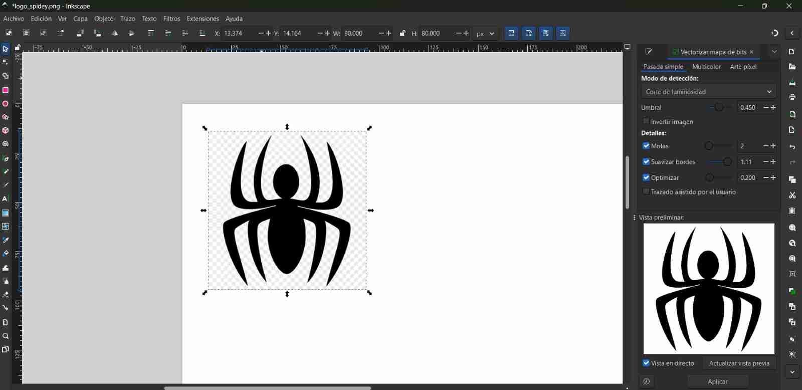
Insert the image you want to vectorize into Inkscape; if it's too large, scale it to the desired size.
2.1.2 Scale the image
2.1.3 Vectorize the image
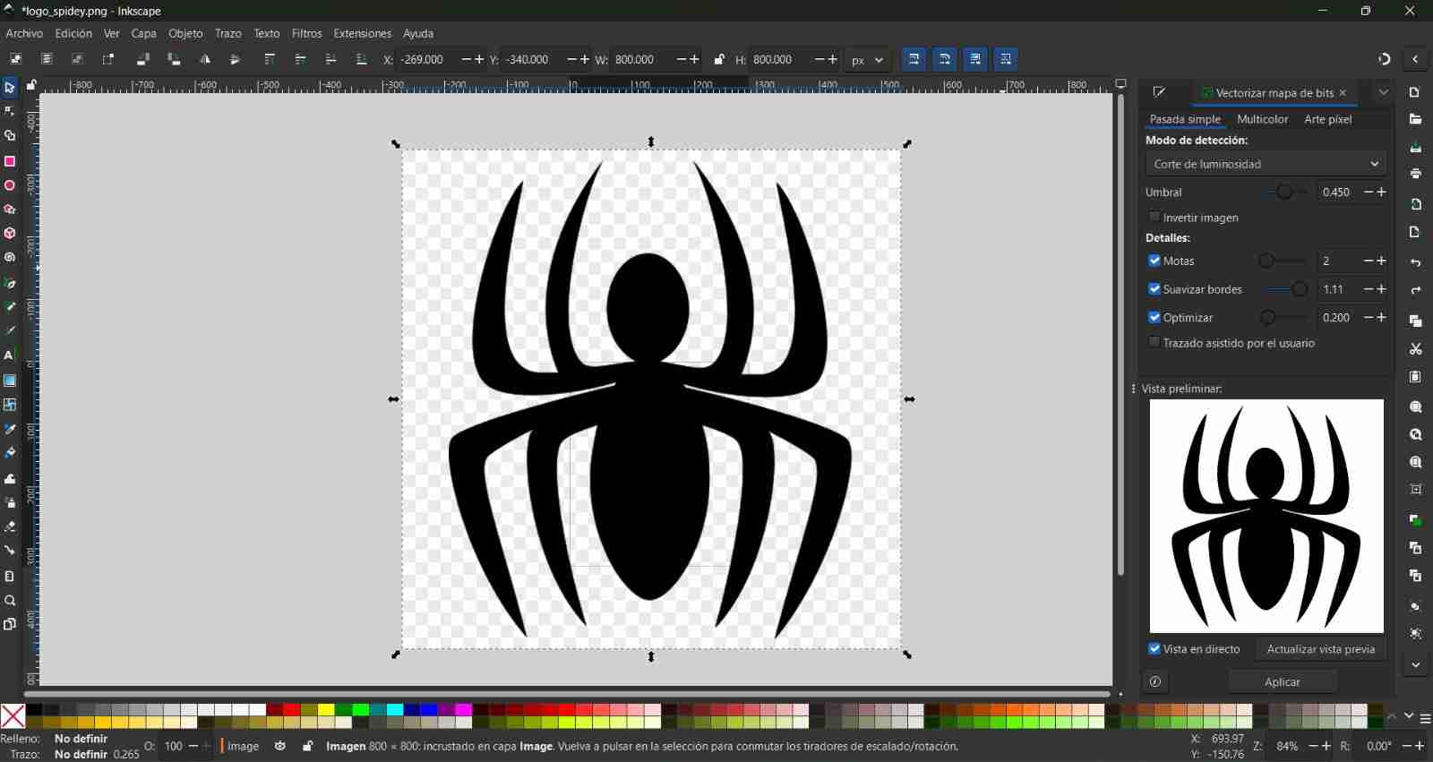
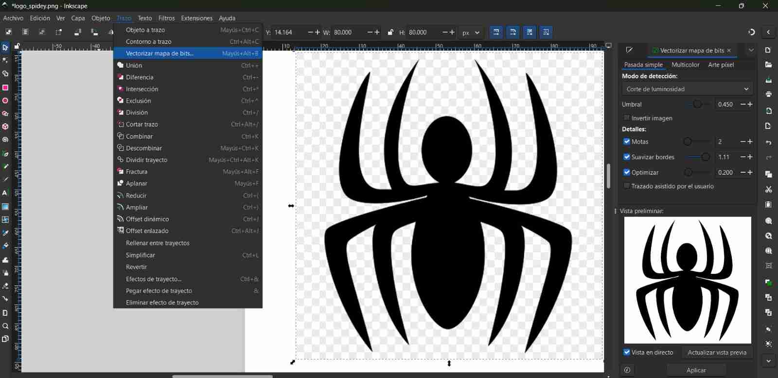
Go to Stroke, then Vectorize Bitmap. This will give us a preview to see how our image will be vectorized. Once we're happy with the result, we'll click Apply.
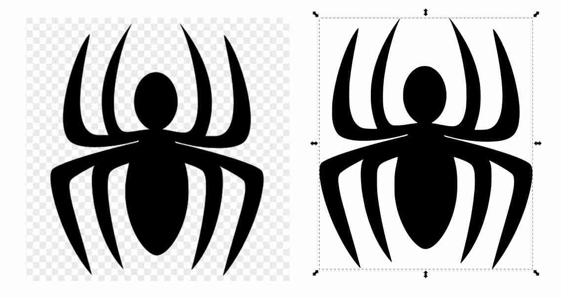
After we click apply we just have to move the vectorized image to other side of the page so we can see it better.
Tips:
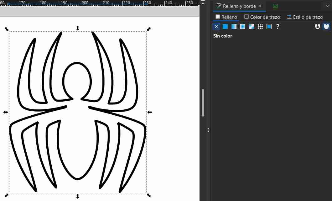
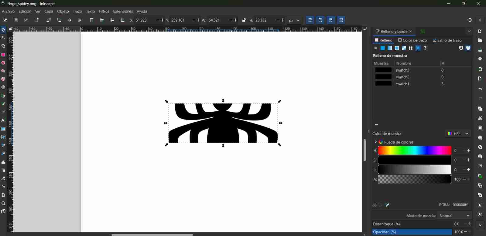
- Add border to the image: If we want to cut with a laser or vinyl, we add a stroke color (it can be any color) and then we remove the fill with the colorless option
2.2 Another case to vectorize image
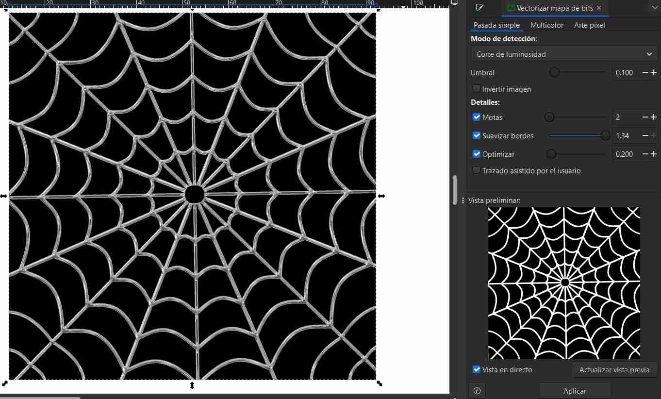
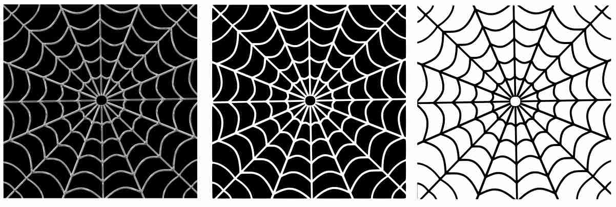
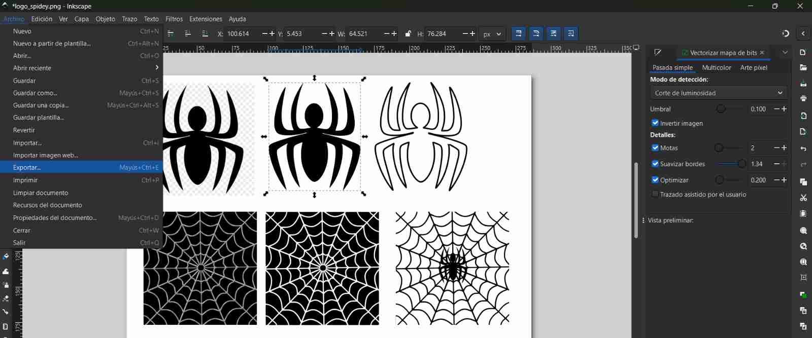
Now I want to vectorize this spiderweb image, but when I vectorize it normally and get the borders, I get details I don't need, like the detail in the spiderwebs or the square border surrounding the pattern.
For these details, you need to modify the default vectorization provided by Inkscape. Go to the "Single Pass" tab and adjust the threshold option until it's the one you want.
Tip
- Invert the image colors
We can also use the "invert image" option, which inverts the blacks and whites; depending on our needs, this may or may not be useful.
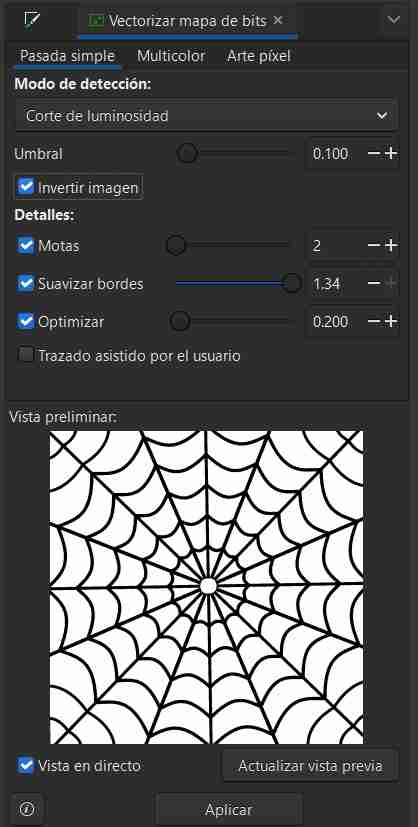
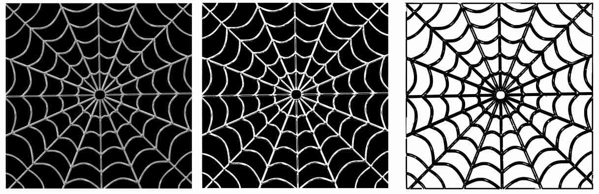
After playing with the threshold there is less detail in both images, in the spiderweb (which is what I wanted) and you can also see the image with inverted colors.
Tip
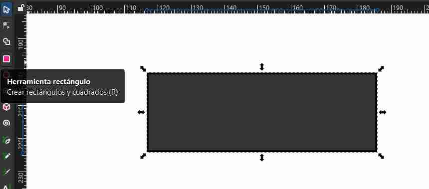
- Trim images
To crop an image, you need to insert any shape, as that is the shape that will be cropped from the image.
We select the shape with which we will cut the image, right-click, select crop and apply crop.
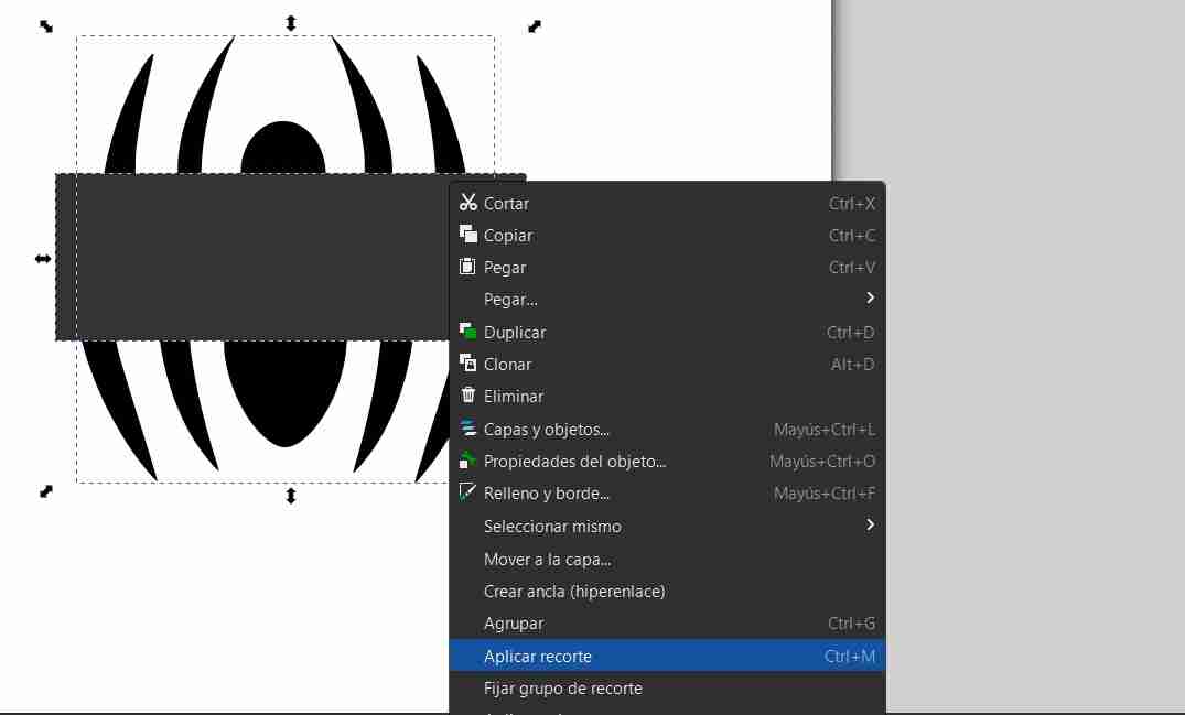
Only the area within the shape we have made will be preserved.
Tip
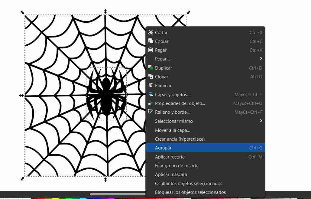
- Combine images
To combine images, select both images with shift, right click and click group.
2.3 Save and export images
2.3.1 Open the export tab
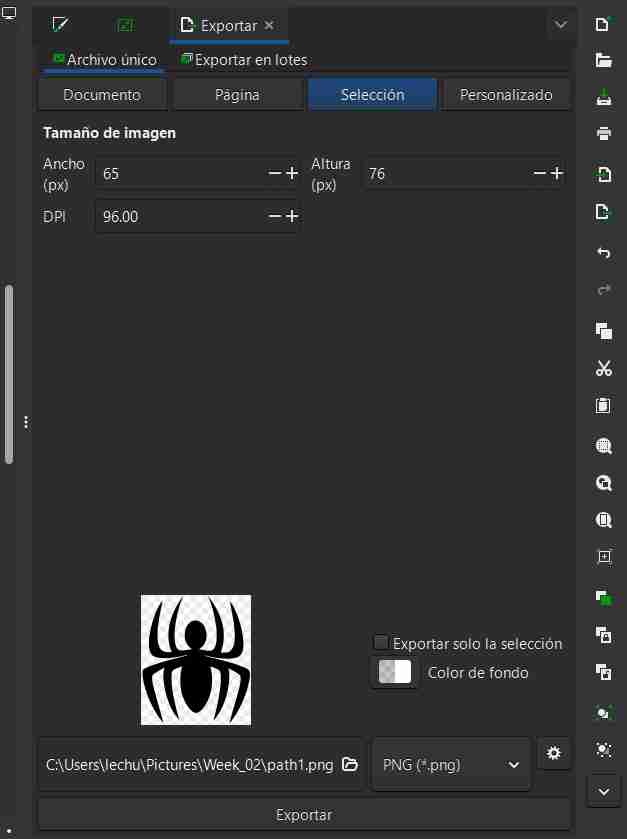
To save an image, go to File, then Export. A tab will open on the right.
2.3.2 Export the image
There are different options for saving, allowing you to save the entire document, a specific page, a custom page, or a selection (which I will use) that allows you to specifically save the image you clicked on. When you clicked on it, you select export.
2.4 Drawing tools
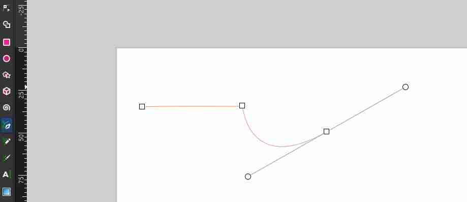
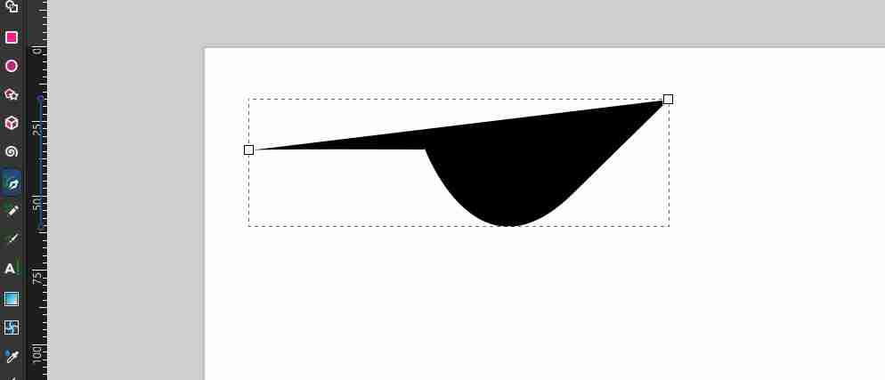
2.4.1 Pen
Allow to draw draw bezier curves and straight lines, after you finish drawing the shape that yu draw will be filled.
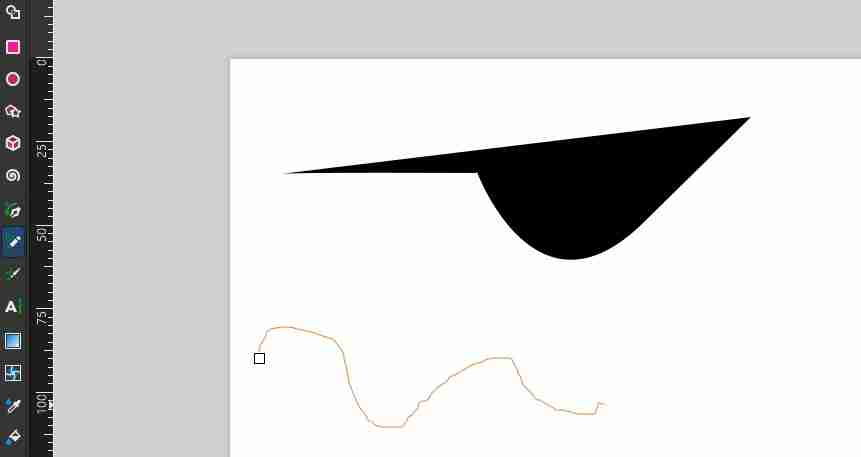
2.4.2 Pencil
Allows to draw freehand strokes and it doesn't fill after finishing
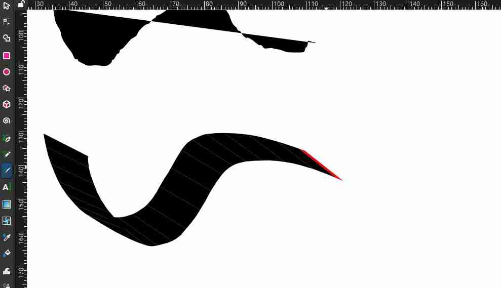
2.4.3 Calligraphy
Draw calligraphic strokes
3. Affinity
Affinity is a professional graphic design software focused on creating and editing high-performance vector and raster graphics. It is used for illustration, 2D drawing, and vectorization, and is known for its precision and efficient workflow.
3.1 How to vectorize images in Affinity?
3.1.1 Insert image
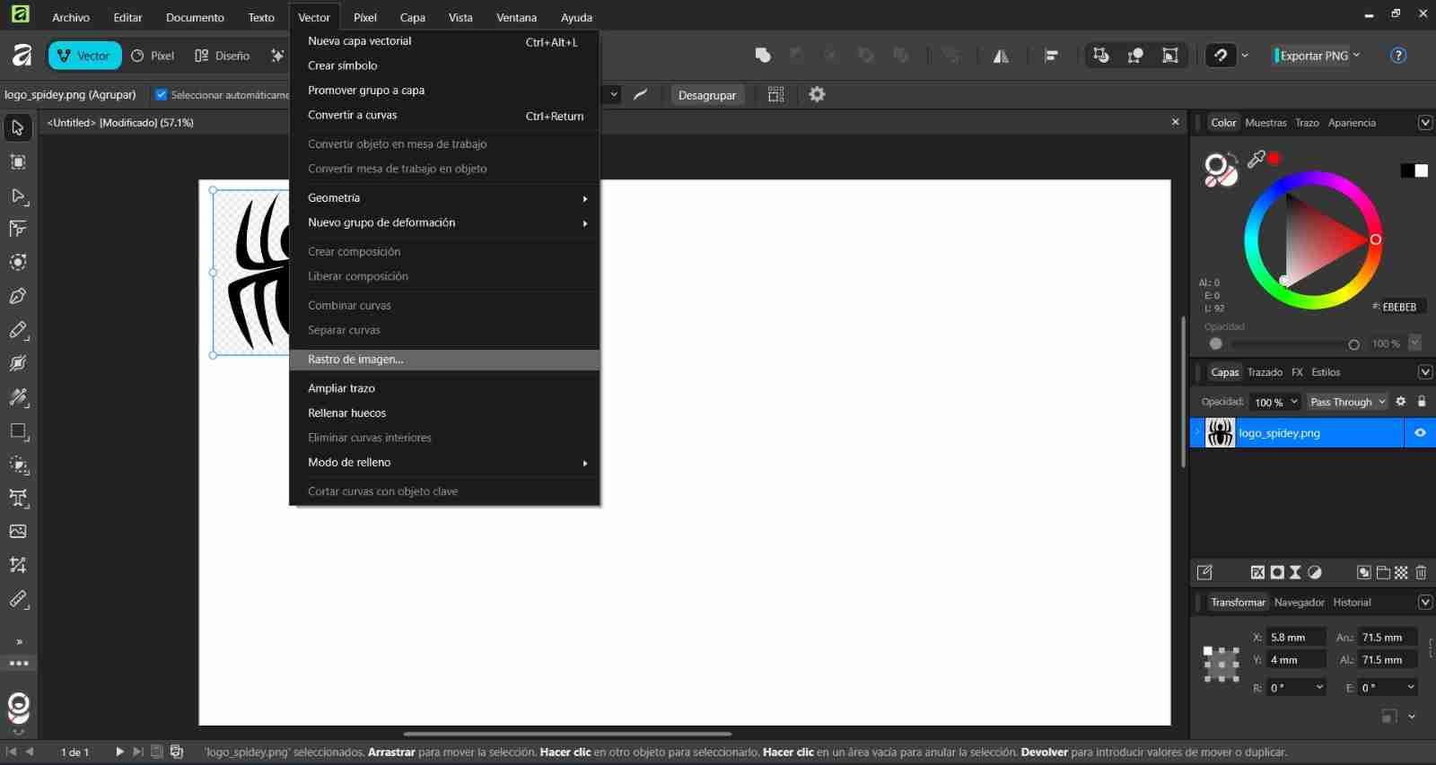
We insert our image, select our image, then click on the vector tab, look for the image trail option and click on it.
3.1.2 Vectorizing the image
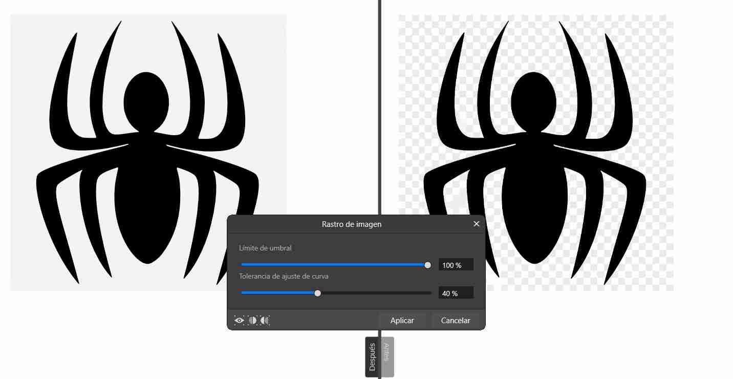
The Image Trace tab will appear with two options: Threshold Limit and Curve Fit Tolerance. A helpful tip is that you can click the button in the middle of the left corner of the window (the one that looks like a circle cut in half) to see the before (right) and after (left) of the image. Threshold Limit allows for more vectors at a lower percentage, which is useful when working with a color image. However, as mentioned before, vectorizing color images is not recommended because they can end up containing a large number of vectors. Curve Fit Tolerance varies depending on the number of vectors applied, so both parameters are related and will differ depending on the needs of each image, click Apply.
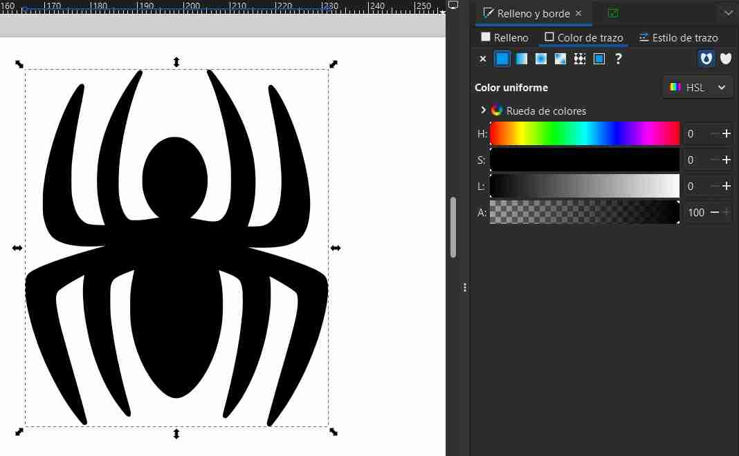
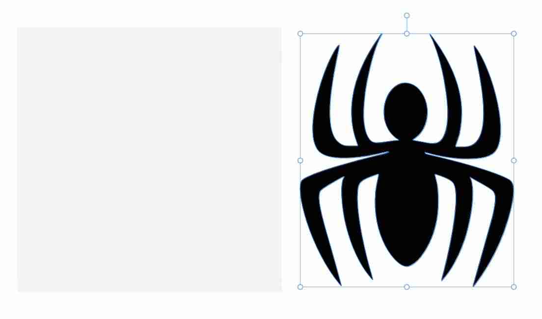
When you click, it seems as if the image hasn't been vectorized, but you have to double-click on the shape you want to modify (in my case, the spider) and move it wherever you want.
3.2 Save and export images
Open file and then export
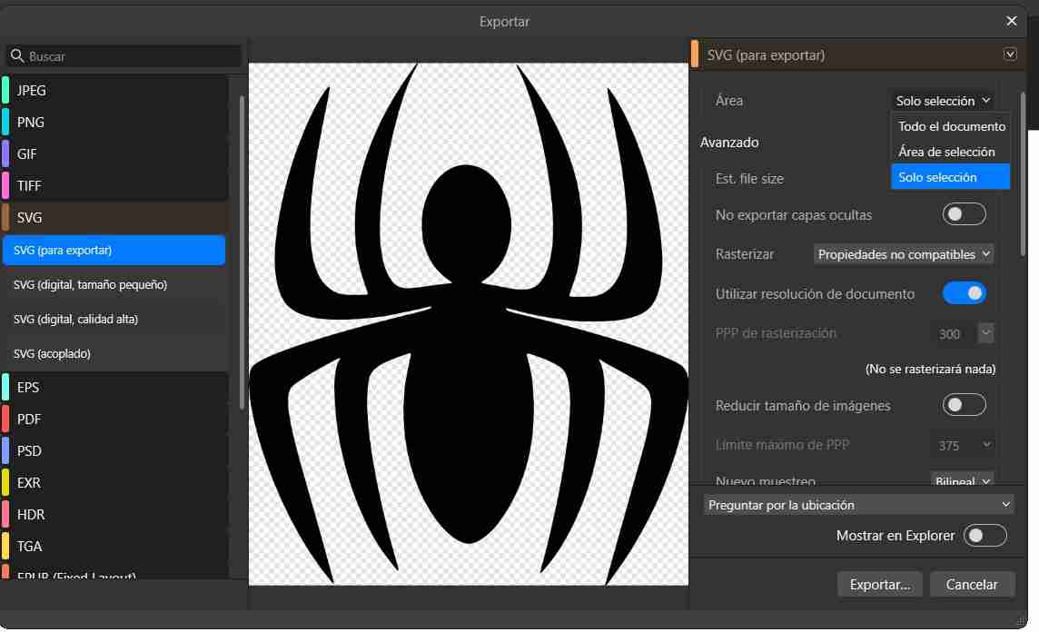
To save our file, go to "File", "Export", "Export", select the "SVG" option to save our file in that format. To save only the area of our vectorized image, click on the box next to "Area" and choose "selection only" or "selection area" (either one works) and save it.
3.3 Other case
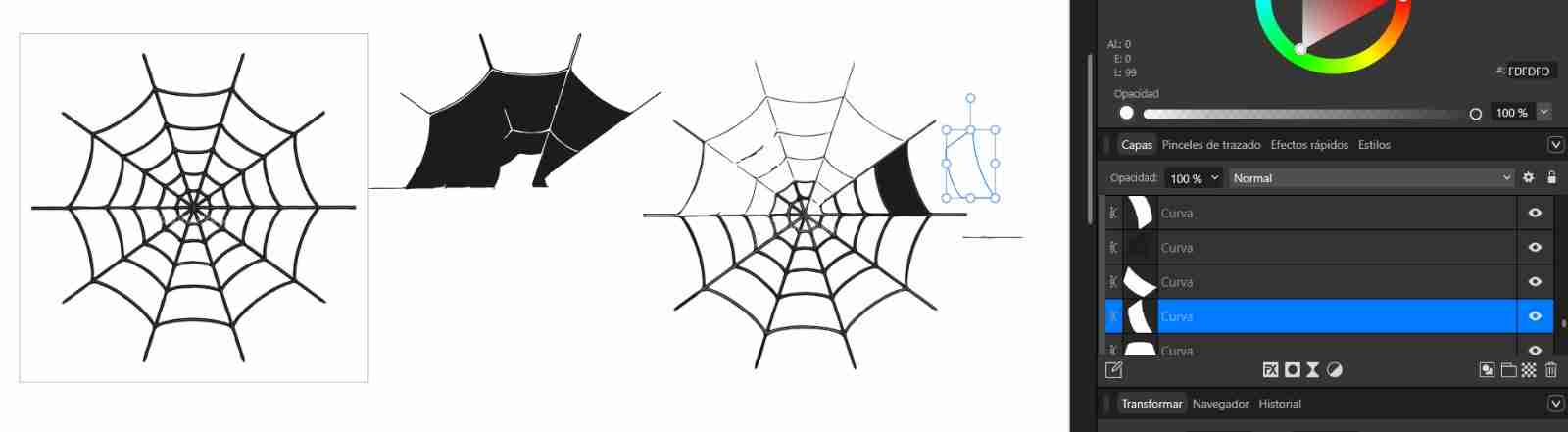
When trying to vectorize an image with defined contours, Affinity literally cuts each section, allowing you to separate them one by one, as in the image. It's not possible to vectorize this type of image so directly, but it's quite useful if you want to modify a specific section or something else.
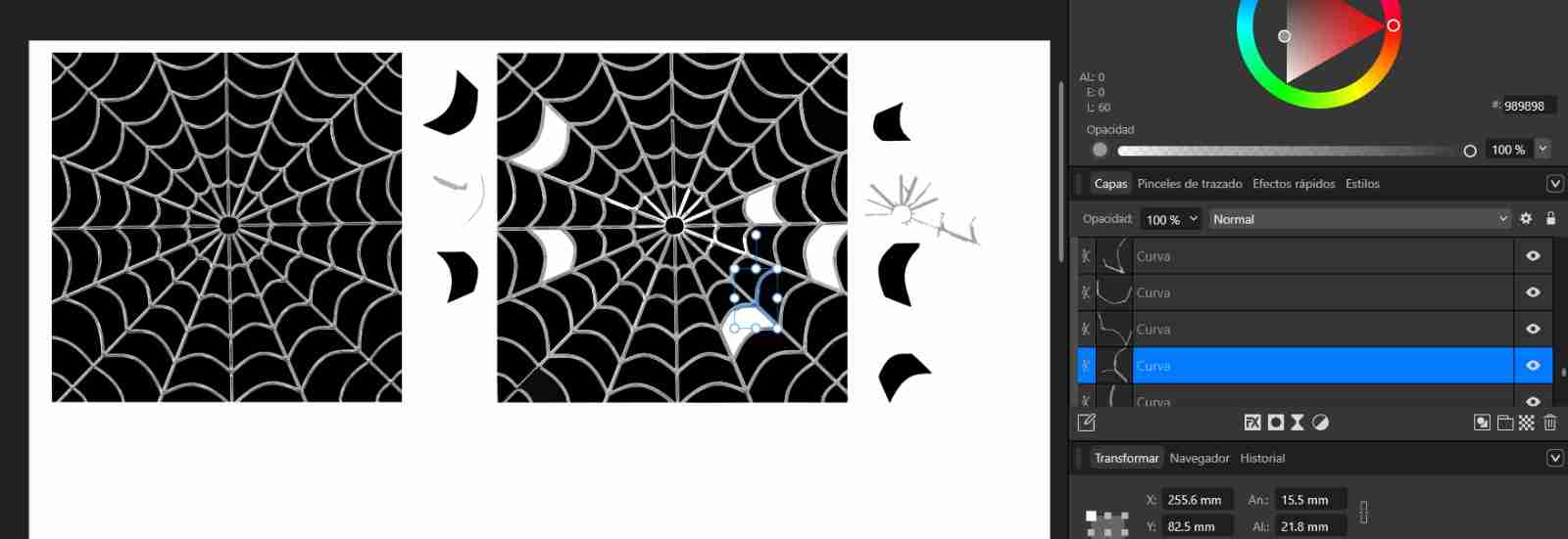
With this other example we can see again that it does the same thing of separating each figure individually and by color, although in this image it seems that the colors of the spider web are the same, they are not, since it separates between gray and black of the spider web.
3.4 Drawing tools
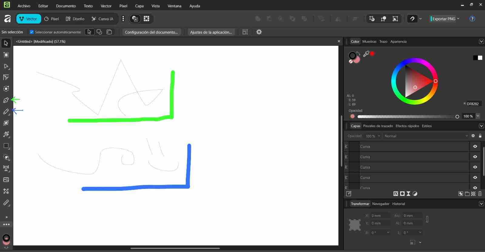
We have 2 drawing tools, which are:
- Pen: Allows to draw straight and curved lines.
- Pencil: It allows freehand drawing.
3. Conclussion comparing both softwares
We can conclude that Inkscape is more efficient for vectorizing images because it allows us to vectorize directly, separating similar colors and offering the option to invert colors and other editing options in an easy and user-friendly way. In contrast, Affinity vectorizes simple images (those with only one shape) like Inkscape, but when you import a more complex image, it separates by specific shapes and colors. Therefore, if there's a slight variation of gray, black, etc., or multiple shapes within the same object, it will separate shape by shape, which is very useful for color images, as these are the ones where we typically want to change a specific color.
4. 3D softwares
3D modeling programs are used to digitally create, visualize, and modify three-dimensional objects, allowing for the highly accurate representation of shapes, volumes, and assemblies. They are key tools for technical design and engineering, as well as for animation and digital art, since they facilitate the simulation, analysis, and realistic presentation of products and scenes before their final manufacturing or production.
Download links:
The aim is to create symmetrical parts in both programs to demonstrate which program is better for each task, although it is already known that Blender is more commonly used for freehand modeling or animations, while SolidWorks is a recommended program for creating symmetrical parts.
5. SolidWorks
SolidWorks is a computer-aided design (CAD) software focused on parametric 3D modeling of parts and assemblies. It is widely used in engineering to design, simulate, and document products with high accuracy.
5.1 How to use SolidWorks
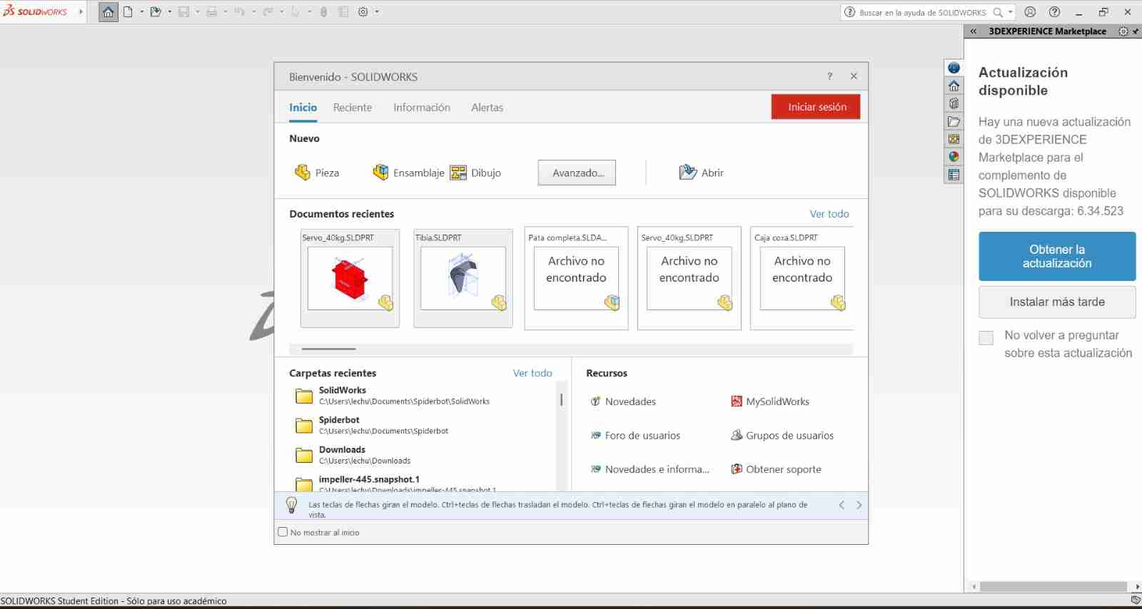
5.1.1 Open a new file
When we open SolidWorks, we are greeted with this tab; we will click on "Part" because we are going to model it.
5.1.2 Enable the drawings
To activate our drawings if they are not already activated, we will right-click on them and click the eye icon.
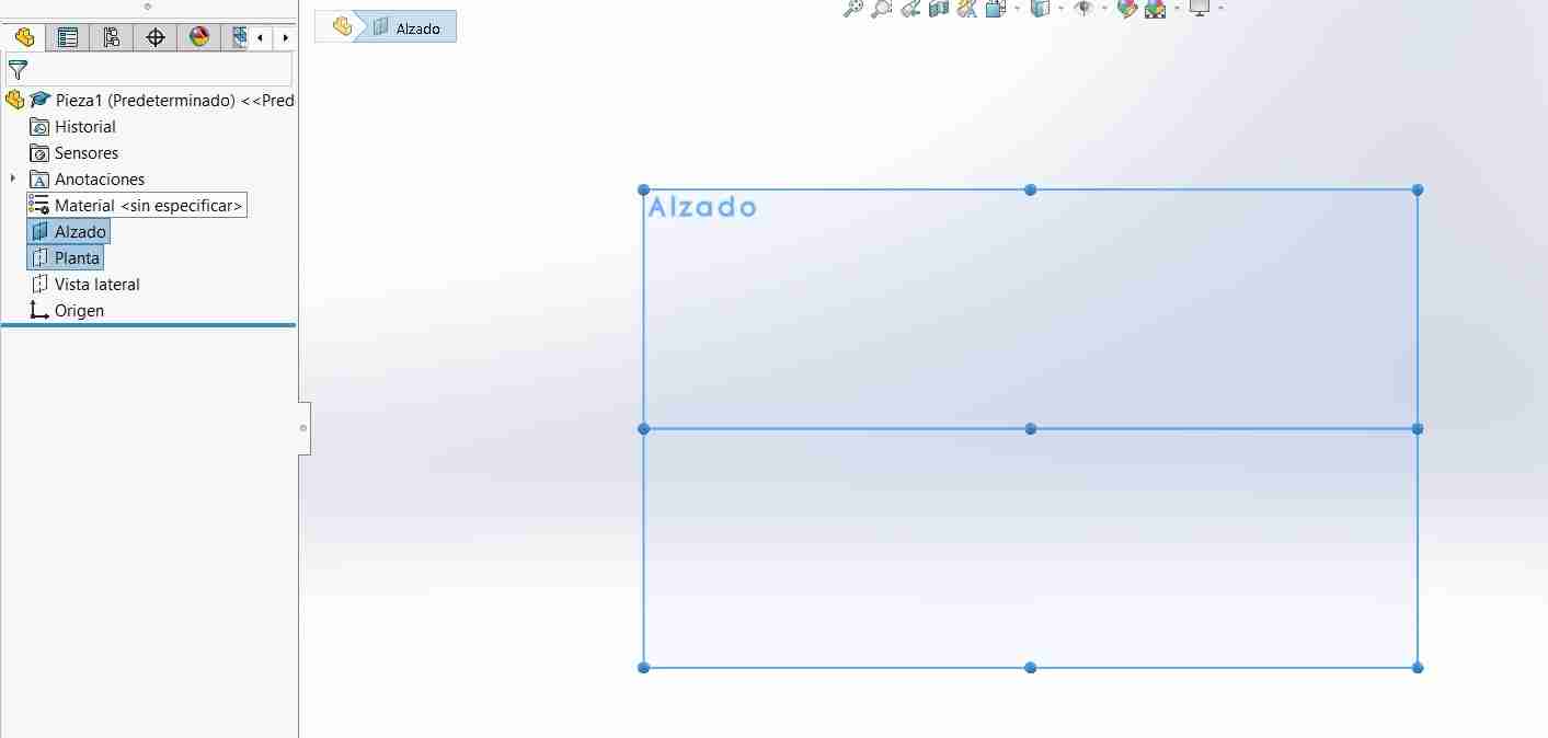
5.1.3 Start ou sketch
To start a sketch, go to the sketch tab and click on sketch. If you have already clicked on a plane, the sketch will start automatically; otherwise, you just need to select a plane.
This toolbar is what we'll use to draw and modify our sketch until we're happy with it. We can insert lines, circles, rectangles, splines, points, and predefined shapes, as well as create symmetries (to make identical shapes on opposite sides) or matrices (creating circular or linear patterns of shapes), and more.
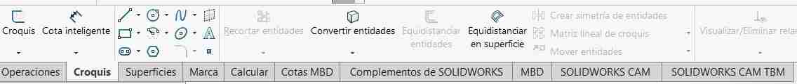
5.1.4 Defining a figure
In order to extrude a shape correctly, it must be well defined; otherwise, we may encounter problems when making modifications later. To define it, we will use smart dimensioning and click on the line of our shape until it has black borders and is shaded on the inside.
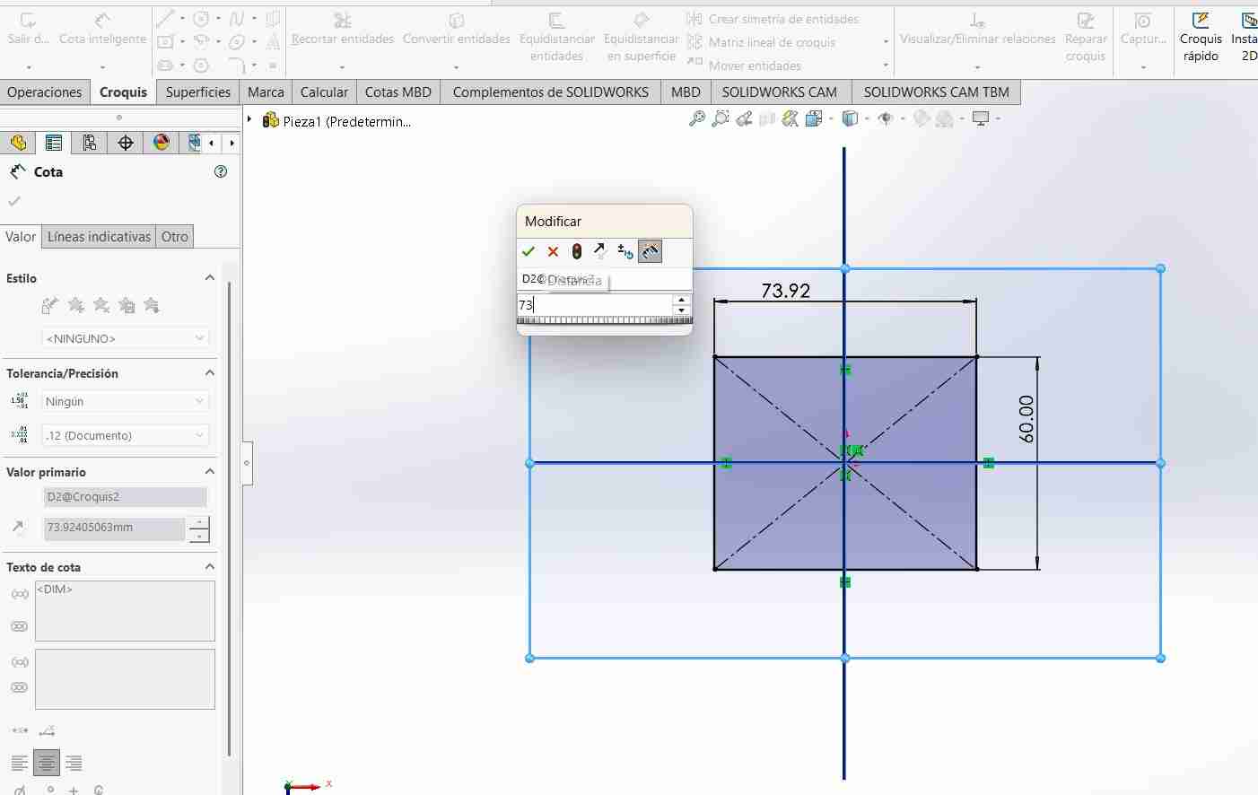
5.1.5 Extruding the figure
Next, we'll use extrude boss to turn our sketch into 3D.
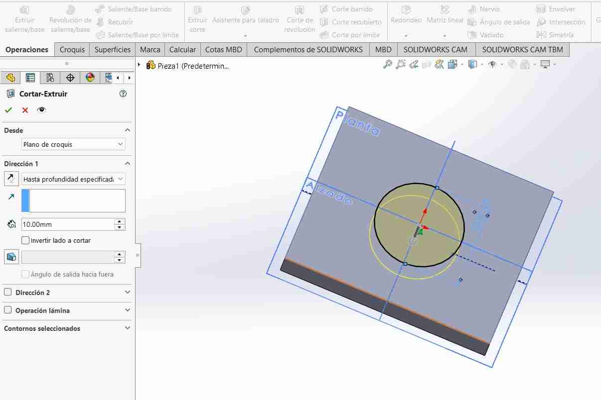
5.1.6 Cutting the figure
To make a cut, we will repeat the process, only at the end, after having our shape defined, we will use extrude cut.
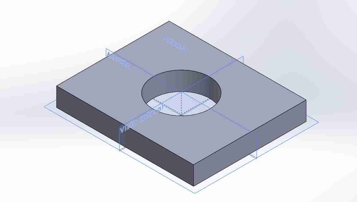
5.1.7 Final result
After modifying our figure this is the result with the basic stuff but the necessary to start modeling in SolidWorks.
What I modeled for my final project
I modeled the tibia of my spiderbot which is a piece easily recognizable because it is the piece that gives hexapods that spider appearance. This a first idea of how it could look like but I definitely know I can do it better so I want to improve the model on the next weeks.
6. Blender
Blender is a free and open-source 3D creation software that allows users to model, sculpt, animate, and render three-dimensional objects and scenes. It is widely used in animation, video games, and visualization due to its versatility and power.
6.1 How to use Blender in the most parametric way?
6.1.1 Input measures
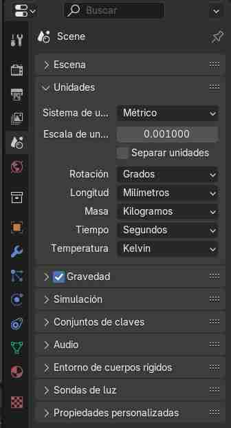
To enable measures, go to scene properties
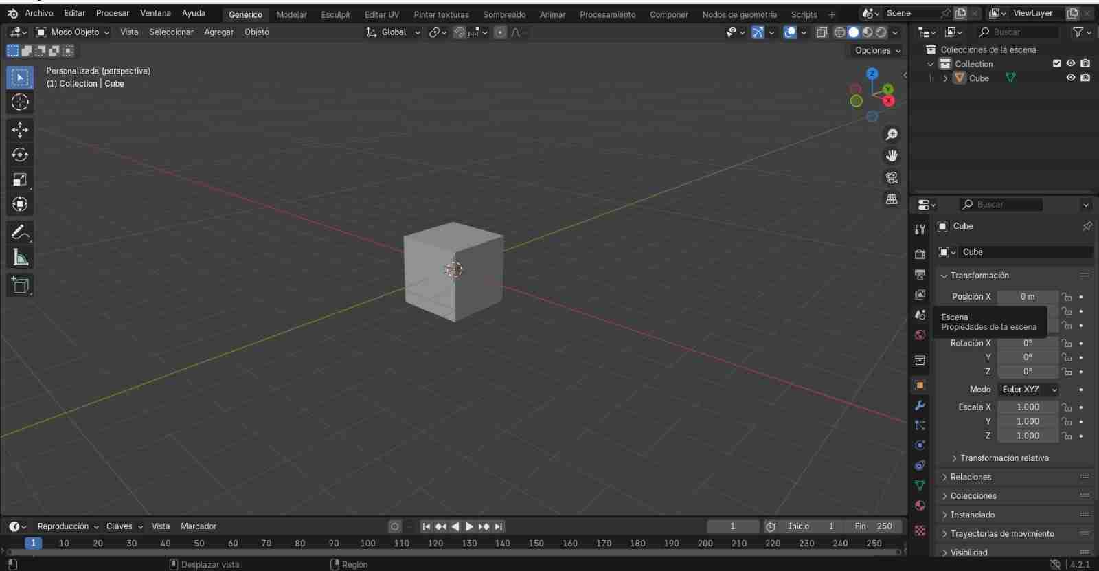
Let's go to the units tab to change our unit system and what we want to measure in.
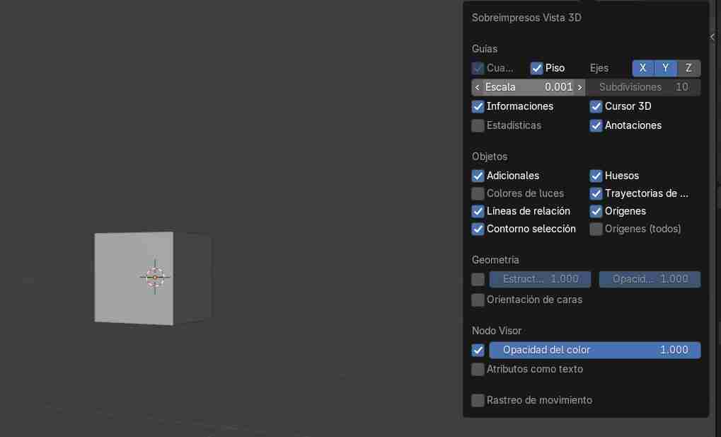
The 3D view overlay needs to be modified to our scale so that the mesh appears in the 3D view.
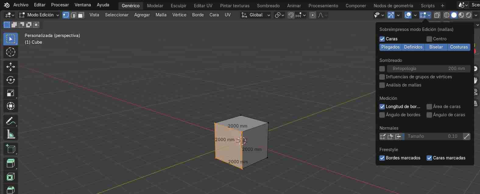
6.1.2 Activate border length
Next, we select the object whose measurements we want to know, switch to edit mode, and go to the "overlay" tab. There, in the measurements section, we activate "Border Length".
6.1.3 Add objects
We add objects in the add tab and from there we choose what we want to add, although those that already come with a body are the mesh objects, the ones from the other tabs will have to be extruded and are a bit more complicated.
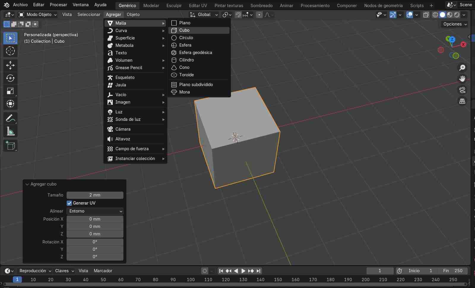
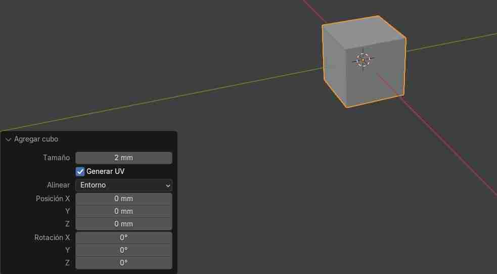
When we change the measurements and insert a new object, we have to modify it from its tab that appears so that it measures what we want.
Commands to move the object
| Command | Function |
|---|---|
| G + Y | Will move on the Y axis |
| G + X | Will move on the X axis |
| G + Z | Will move on the Z axis |
We can move a specific amount by typing it with the numbers on the numpad, so if we type G + X + 5 it will move from the object's origin (usually its center) to having traveled 5 units in Blender (the visible mesh).
Commands to rotate the object
| Command | Function |
|---|---|
| R + Y | Will rotate on the Y axis |
| R + X | Will rotate on the X axis |
| R + Z | Will rotate on the Z axis |
Specific angles can be rotated by typing the angle on the numpad, just like movement commands.
Tips
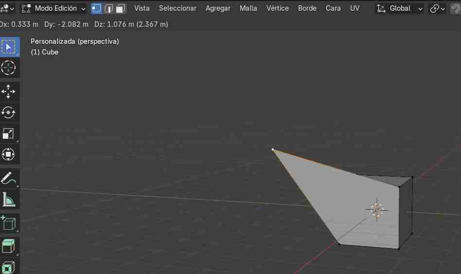
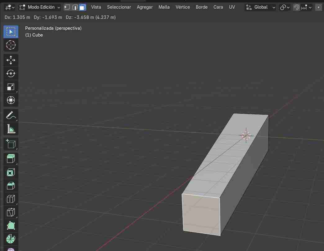
- Extrude: Selecting a face, side, or vertex and pressing E will extrude the selected area. Specific measurements can be extruded by typing the measurement on the numpad.
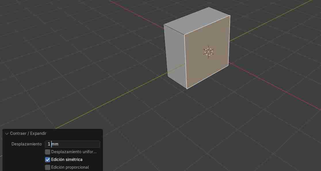
- Shrink: To make a face bigger or smaller, use ALT + S and move the area you want to reduce. For more precision, you can use the tab in the upper left corner and specify the desired size.
6.2 Modeling tools
6.2.1 Edit mode
Edit mode allows us to model by modifying the faces, vertices, and edges of the object, either by moving them with the mouse or by moving them along the axes using the commands mentioned above.
- Vertex
- Edge of the object
- Face

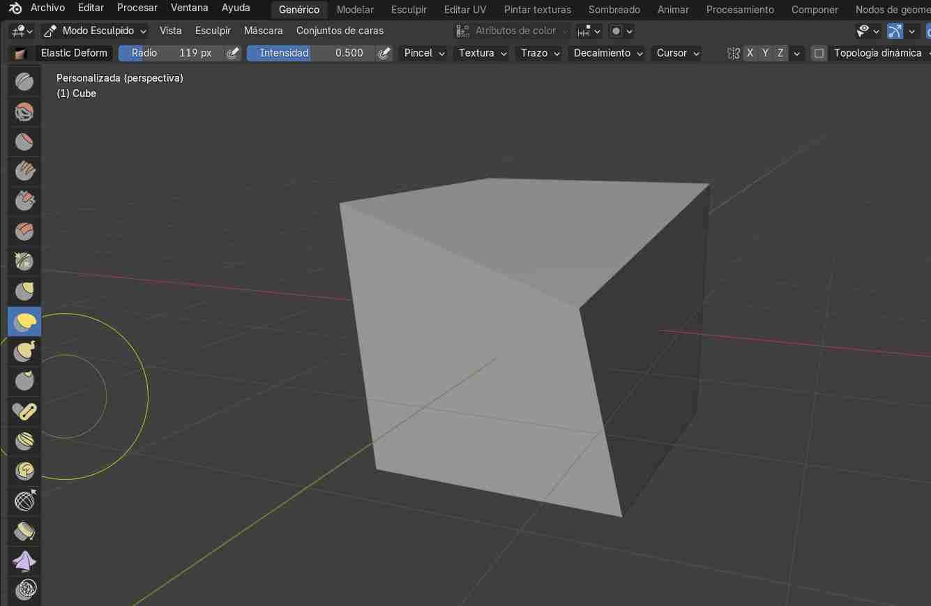
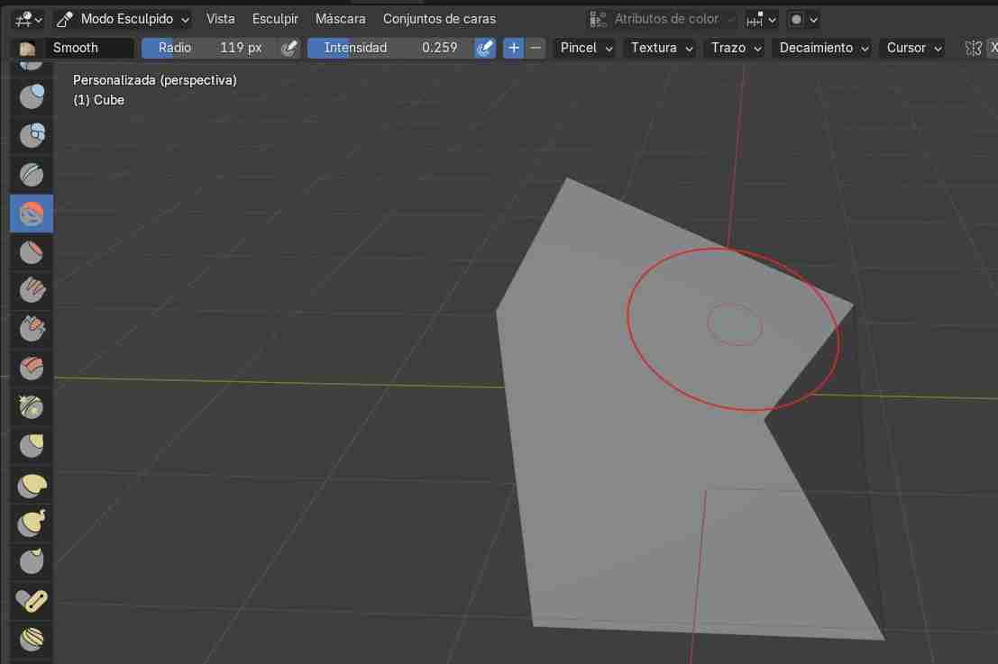
6.2.2 sculpt mode
It's more free because we can deform the object we have however we want, although this does add more polygons and makes the meshing a bit more complicated when transferring it to another application, but this is usually never a problem.
- Modeling / Geometry Tools: They allow you to lengthen, stretch, or deform the object to your liking.
- Transformation tools: Allow us to smooth the surface we are working on.
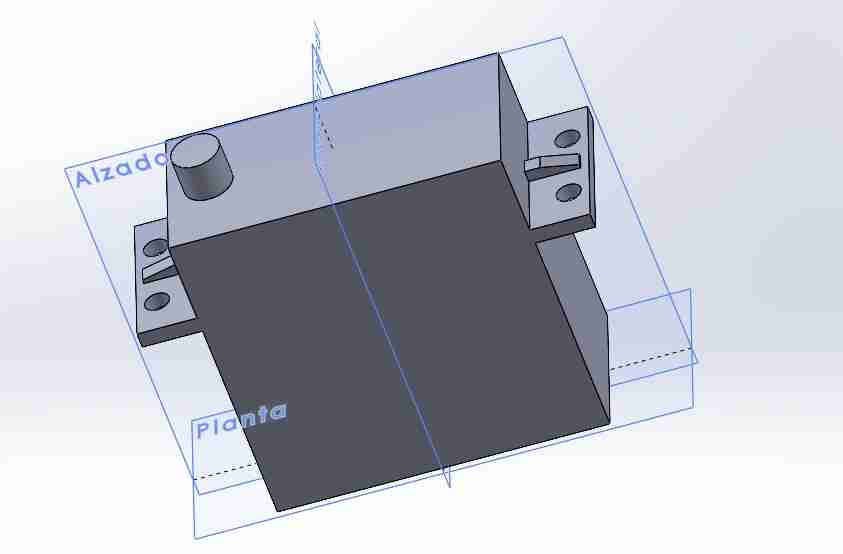
Parametric modeled
I modeled a parametric servomotor of 40kg, which is the one I will be using in my final project, to demonstrate that is posible to model this kind of things.
What I modeled for my final project
As it was a comparisson I tried to model the tibia of the spiderbot to see which software suits me better.
7. Conclussion comparing both softwares
SolidWorks is better for creating the tibia structure, as its parametric nature makes it easier to establish size relationships. While Blender can be parametric, working with complex shapes becomes difficult when dealing with specific measurements. It's more of a software I would use to give each part of the Spiderbot a nice design by modeling the "shell" of each part, such as the tibia shell.
8. Rendering using SolidWorks
8.1 Select the piece to render
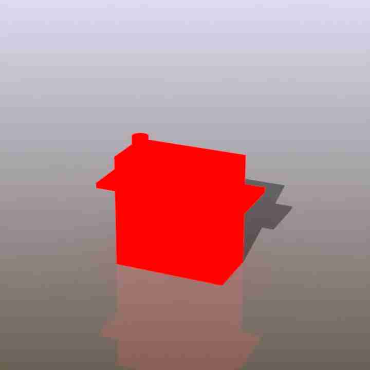
We must have a piece if we want to render so, in my case I going to render the servomotor piece I modeled.
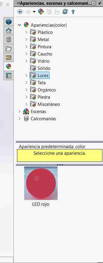
8.2 Apply the material and background
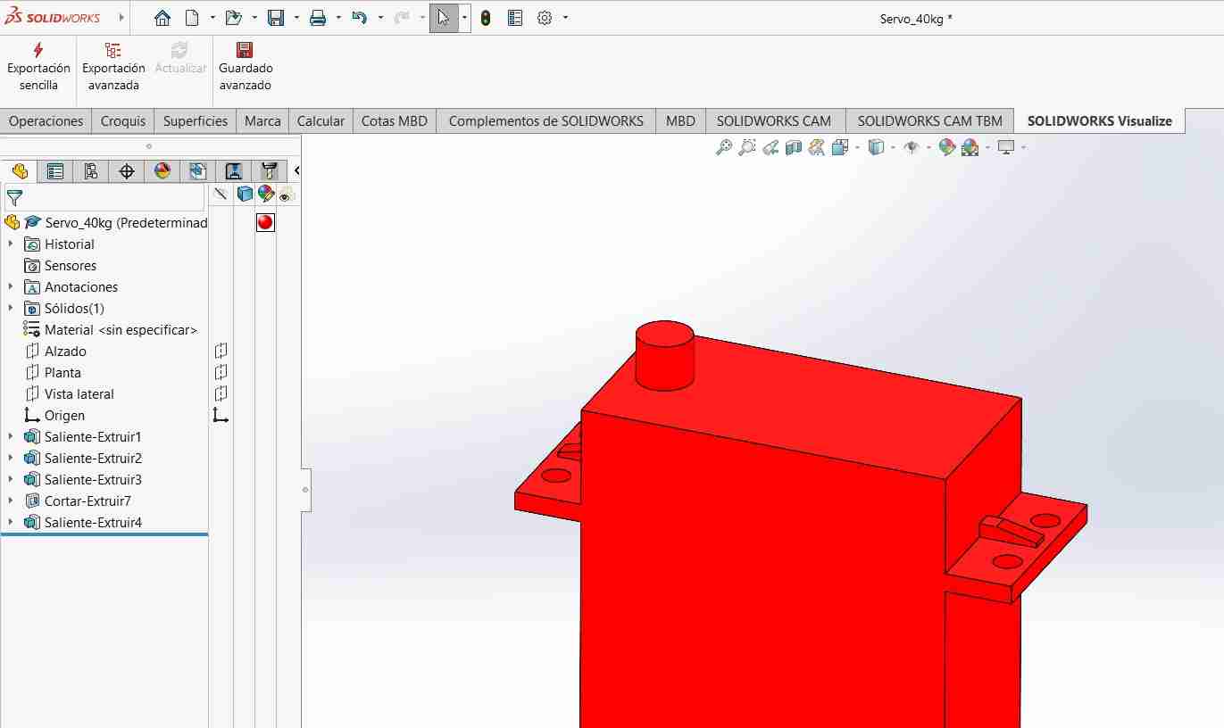
On the right side we will click on the Appearance, Scenes and Decals button, and there we can select the material and/or the scenewe want our object to be made of or to be in; we just need to grab the material or the background and drag it to the object.
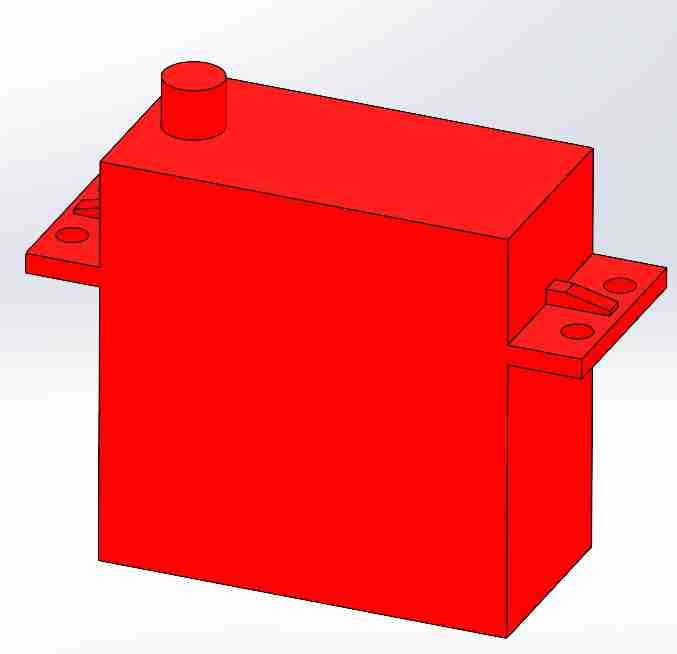
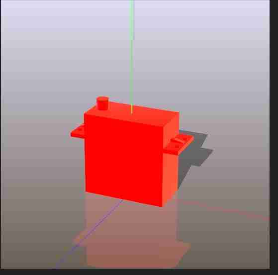
After we drag the material on the object it should turn the color of the material, my case it turned red.
8.3 Enable SolidWorks visualize
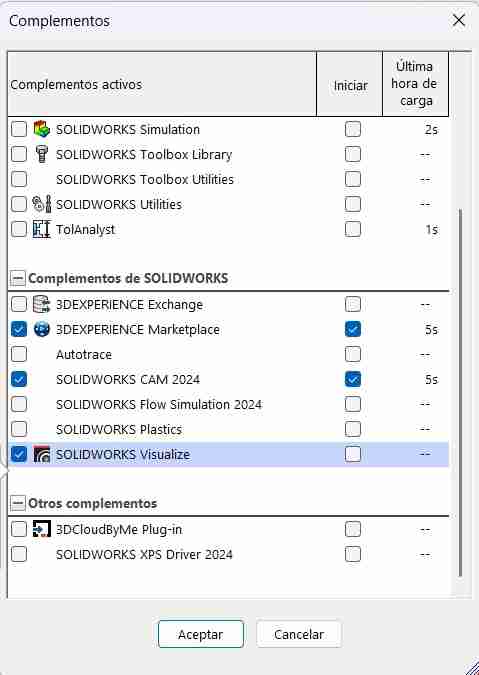
SolidWorks visualize is not activated by default, therefore we will have to activate it. For this we go to tools, add-ons.
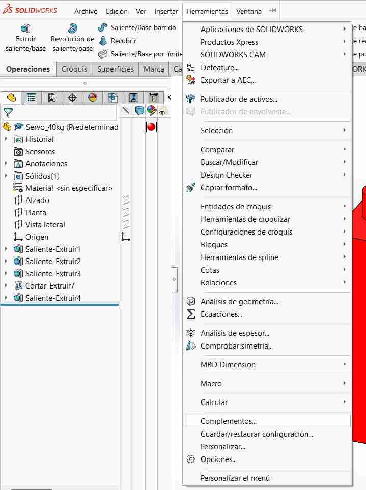
We activate it and wait a moment for the tab to appear in our taskbar.
8.4 Enter to SolidWorks visualize
We need to go to our SolidWorks visualize tab and select simple export.
After a moment, this menu will open.
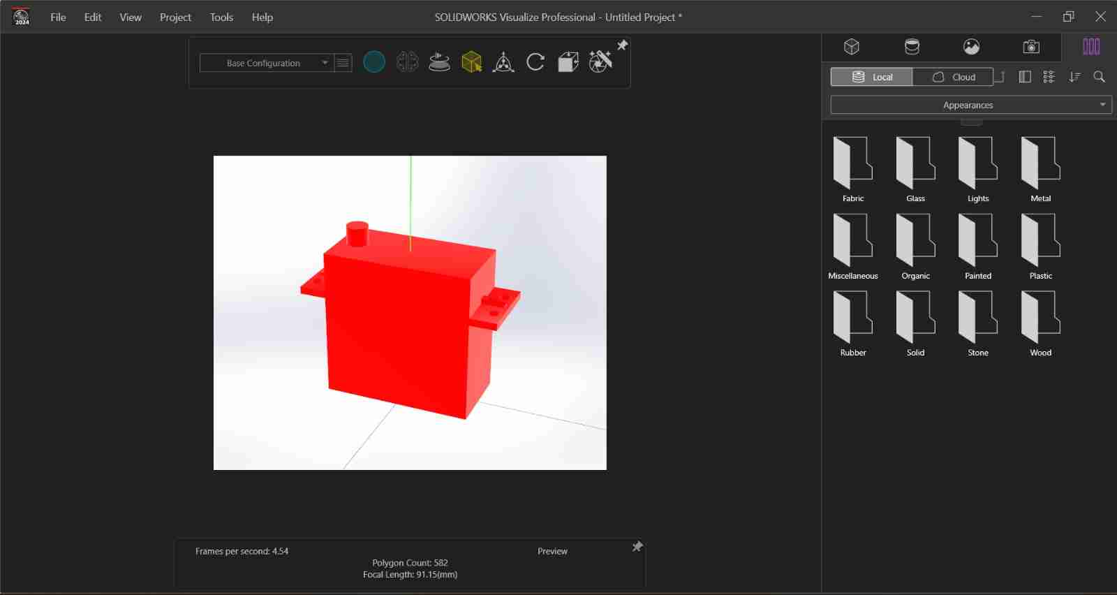
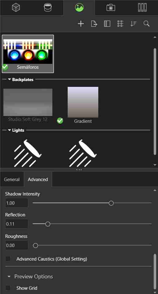
8.5 Moddify the background, material (optional, we've already did this) or lights
You can modify the appearance, lighting, and background of the render using the menu options on the far right. In my case, I changed the background and increased the reflection for a more noticeable result.
SolidWorks even give us a preview of how it would look like the final render
8.6 Save the render
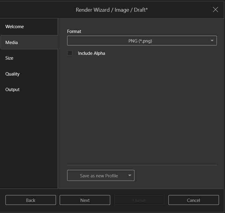
Using the tab at the top right (pink), we will generate our render. We click it and it will appear the next tab.
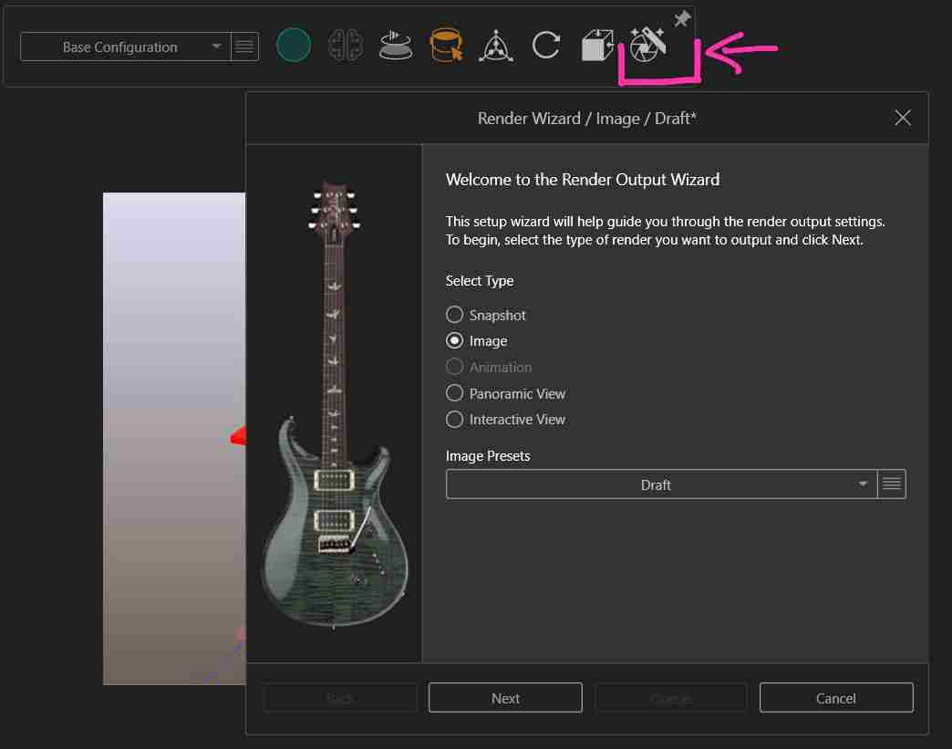
Allowing you to change the format of the rendered image, its size, quality, and where it will be saved.
It is automatically saved in the folder we have chosen.
9. Compressing images
GIMP is a free and open-source raster image editing software that allows users to retouch photographs, create compositions, and perform basic graphic design. It is an open-source alternative to commercial editors and is widely used for image editing and manipulation.
9.1 Open GIMP
9.2 Insert our image
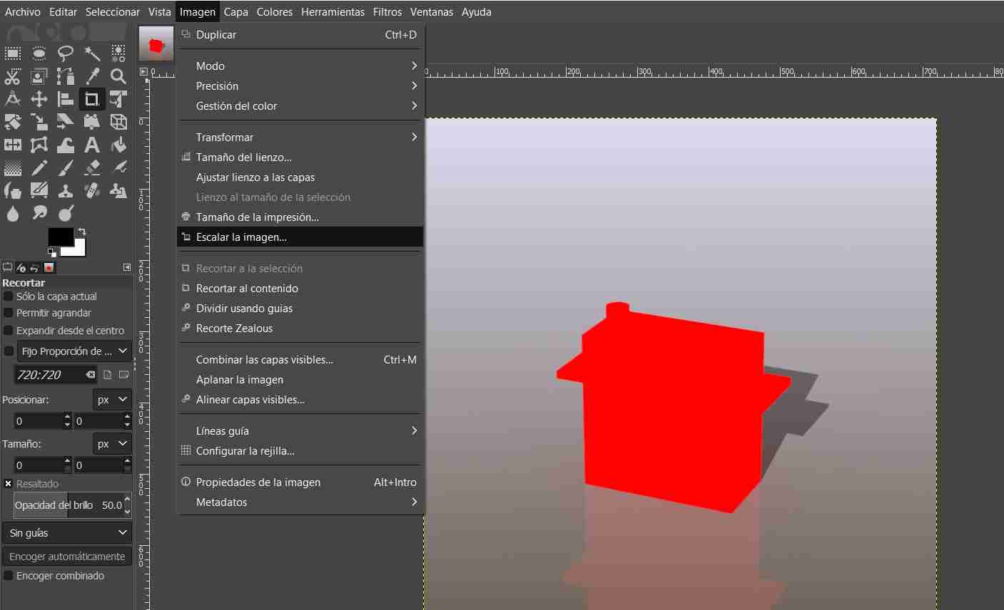
Insert your image, go to the image tab and click on scale image.
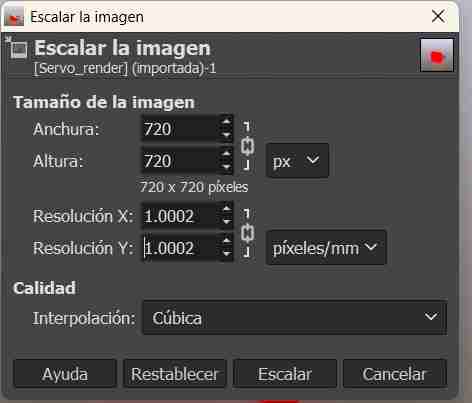
9.3 Scale your image
We need to lower the resolution in x and y.
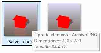
9.4 Export your image
To export, go to file, export ss, and in extension select WebP.
10. Compressing videos
FFMPEG is an open-source toolkit for processing audio and video from the command line. It allows you to convert formats, compress, record, and manipulate multimedia files with great flexibility and precision.
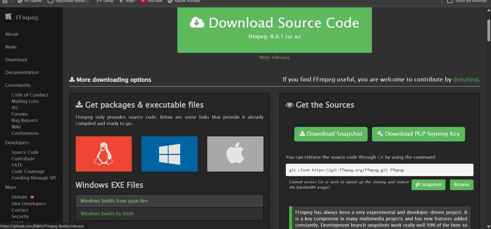
10.1 Download FFMPEG
Click on Windows builds by BtBN, download the .zip file by clicking on it, and extract it to a folder you'll remember.
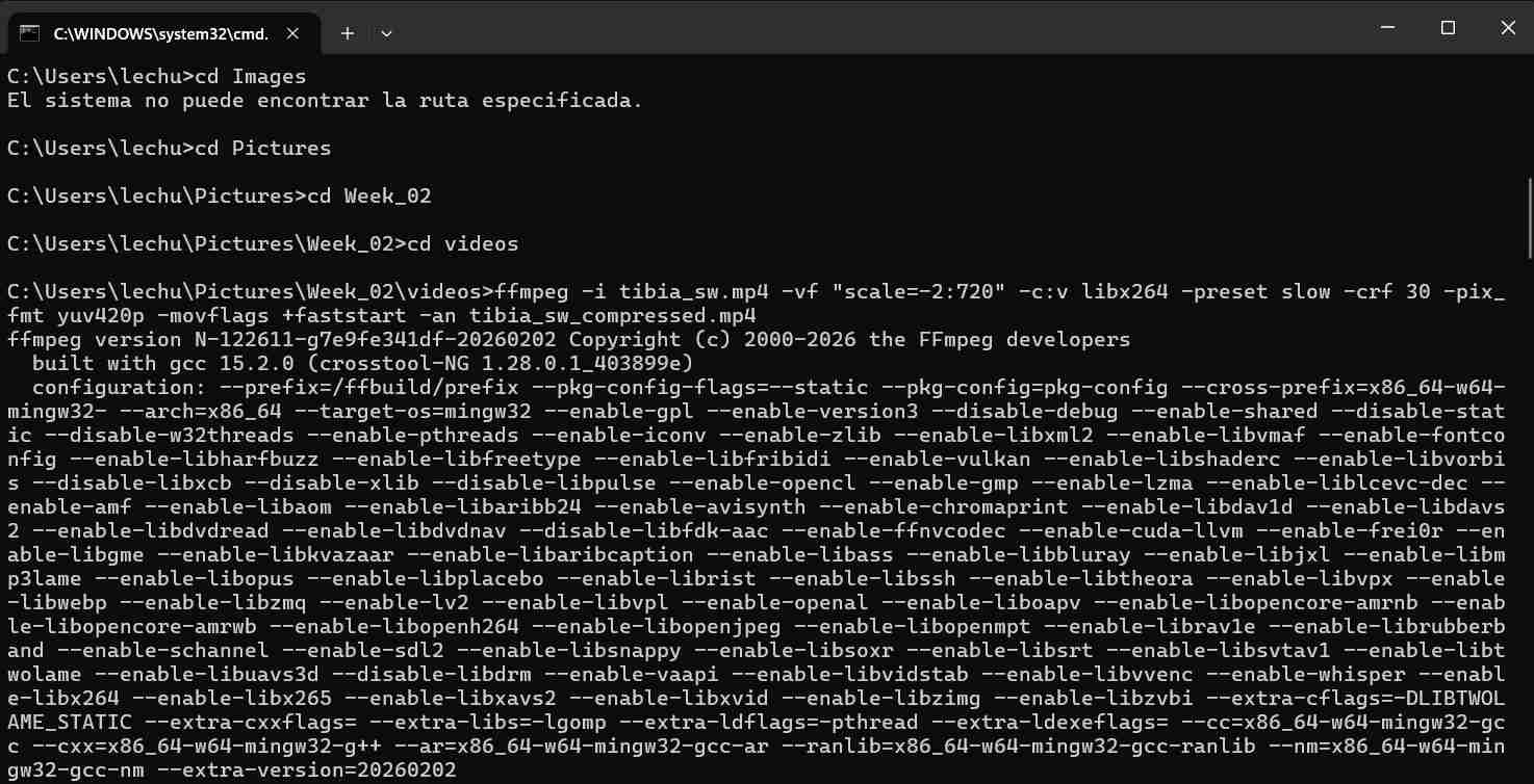
10.2 Input the commands
We open our terminal and use ffmpeg -version to call it, then we access our folder where the videos are located.
Commands to use FFMPEG
| Command | Function |
|---|---|
| ffmpeg -i input.mp4 | Call the program and define the input file (videoname.mp4) |
| -vf "scale=-2:720 | Change the video resolution |
| c:v libx264 | Universal compatibility standard |
| preset slow | Determine the compression speed; the slower the speed, the better the compression. |
| crf 30 | Constant Rate Factor (CRF) value for quality control.The range is from 0 to 51, where 0 is lossless and 51 is worst quality. |
| pix_fmt yuv420p | Ensures compatibility with most players and browsers |
| movflags +faststart | Optimizes the video for streaming by placing metadata at the beginning of the file. |
| an | Removes audio from the output video. |
| output_new.mp4 | Name of the output file. |
We open our terminal and use ffmpeg -version to call it, then we access our folder where the videos are located.
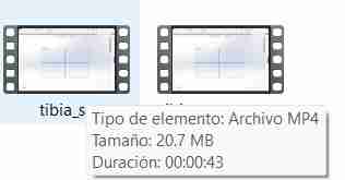
The basic formula to compress any video is "ffmpeg -i input.mp4 -vf "scale=-2:720" -c:v libx264 -preset slow -crf 30 -pix_fmt yuv420p -movflags +faststart -an output_new.mp4"
It will be automatically be saved on the same carpet
Files created
Click on the "Download ZIP" to download all the files I made in the 4 softwares