Computer-Controlled Machining
For this week we must learn how to use router machines, as well as design a useful piece of furniture. In my case, I decided to make a bookshelf or shelf unit. Since I do not have a designated space to store my belongings, I decided to build one.
Individual project
- Make (design+mill+assemble) something big
Design in SolidWorks
It is important to have an idea of what you want to manufacture. In this way, the drawing can be created in a CAD program in order to generate the parts.
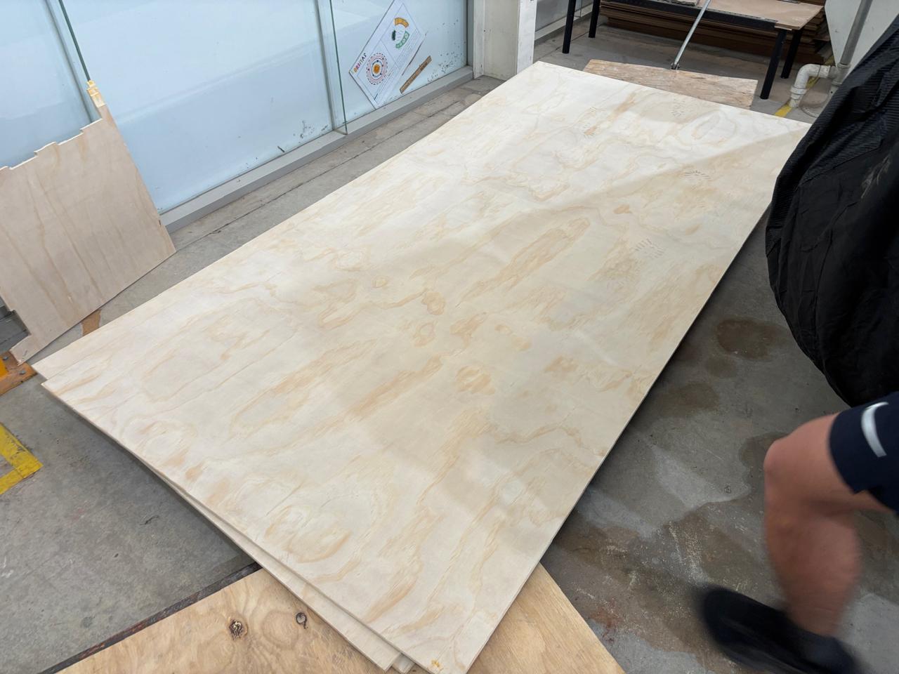
In my case, it was helpful to first sketch by hand how I wanted my bookshelf to look. Afterwards, considering the size of the material, which was 1.22 m × 2.44 m with a thickness of 12 mm, I began modeling each piece of my shelf one by one.
The first piece I created was saved, and I used it as a reference to design the second part. I continued working in this way until all the corresponding pieces were completed.
Once all the pieces were created, I assembled them in SolidWorks to visualize the final result.
The steps I followed to complete the furniture design were very simple. Thanks to the previous weeks of practice, it was much easier for me to create a design that included joints such as slot joints and press-fit joints. In this way, I obtained the following design.
Finally, I created the technical drawings of all the pieces in a single file, which was saved in DXF format.
VCARVE
At my university we use a program called VCarve. This software allows me to determine the cutting speed, cutting depth, tool selection, and other machining parameters.
The university has two types of router machines: the Asiarobot and the March 2/3. This is important because when saving the code, it must be done according to the type of machine that will be used.
Steps Followed
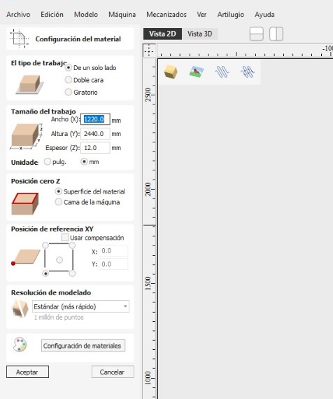
- Open the VCarve program and select “Create a New File.”
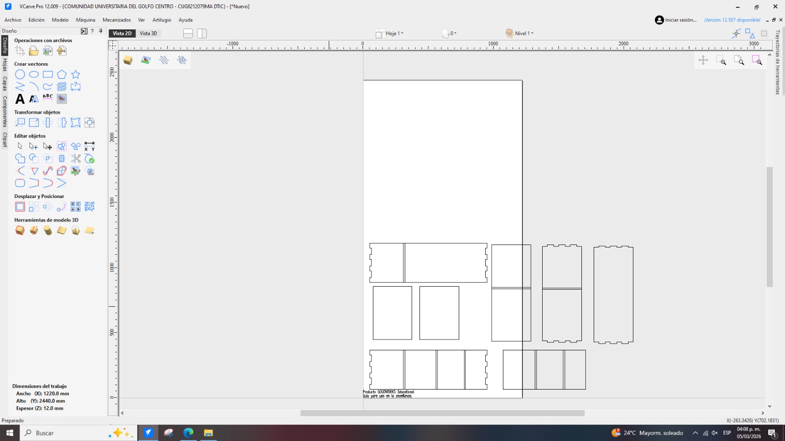
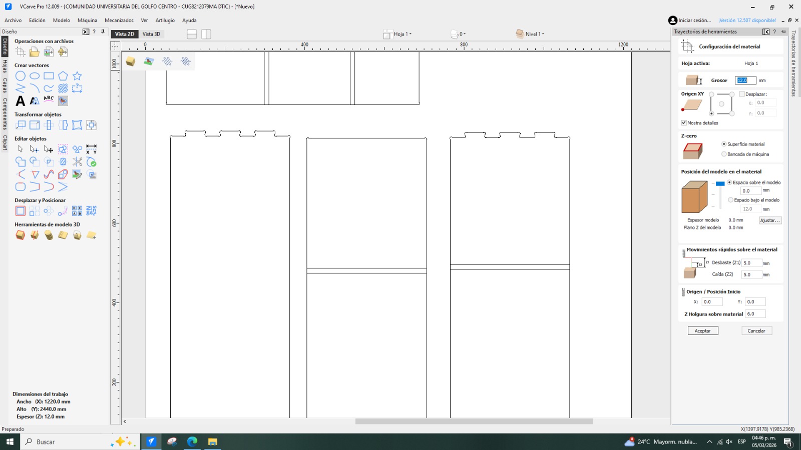
- The material setup window will appear in the interface. It is important to correctly enter the material dimensions. In my case, the material had a width of 1220 mm, height of 2440 mm, and thickness of 12 mm. For the job type, I selected single-sided machining, with the surface origin starting at coordinates X = 0 and Y = 0. After entering these parameters, click Accept.
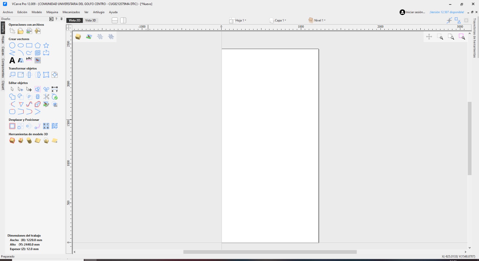
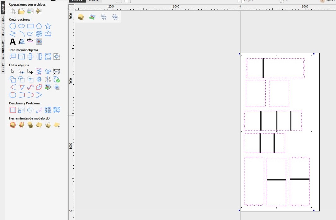
- The main program interface will open. On the left side, you will find tools for creating vectors, transforming objects, editing them, moving them, or using 3D tools.
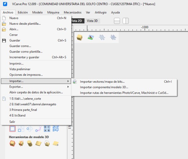
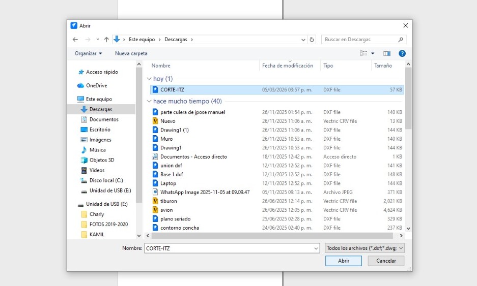
- To add the DXF file containing the pieces, select File → Import → Import Vectors/Bitmap.
- After completing the previous step, a window will open where you can locate your file. Select it and click Accept.
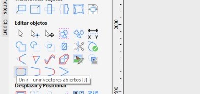
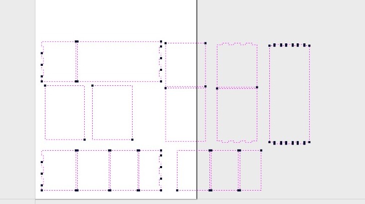
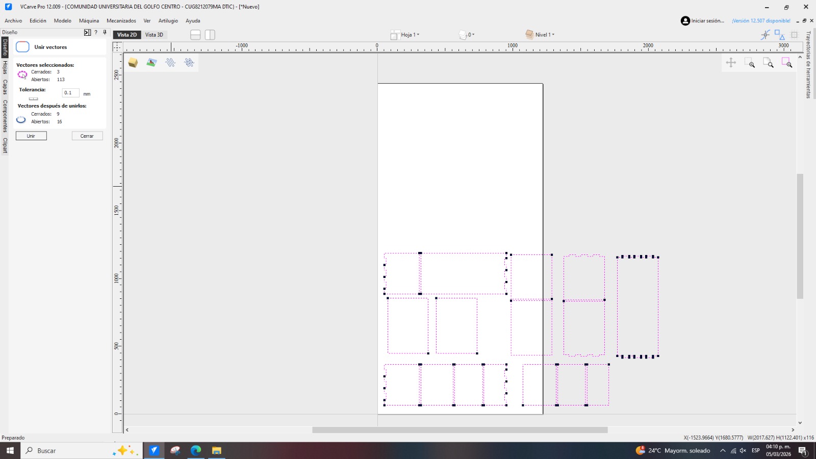
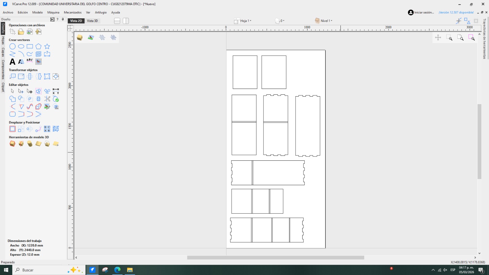
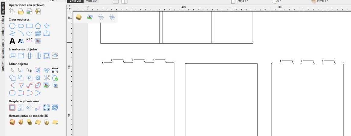
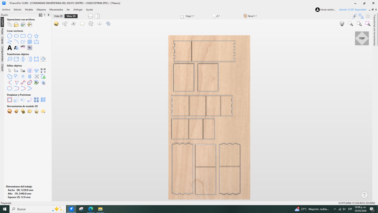
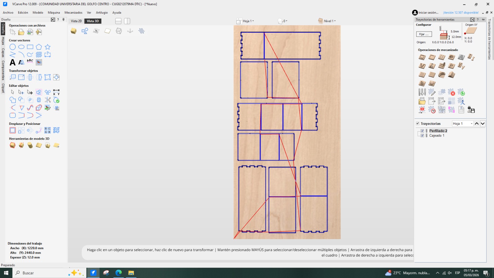
- In my case, the following shapes appeared. I deleted the letters that were automatically added, since they were not necessary. Then, I selected all the pieces and, in the “Edit Objects” section, used the “Join” tool to combine vectors that were separated. I used a tolerance value of 0.1 mm and joined them.
- After that, I arranged all the pieces within the working area.
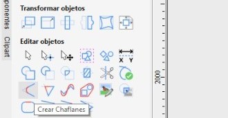
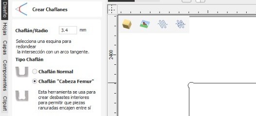
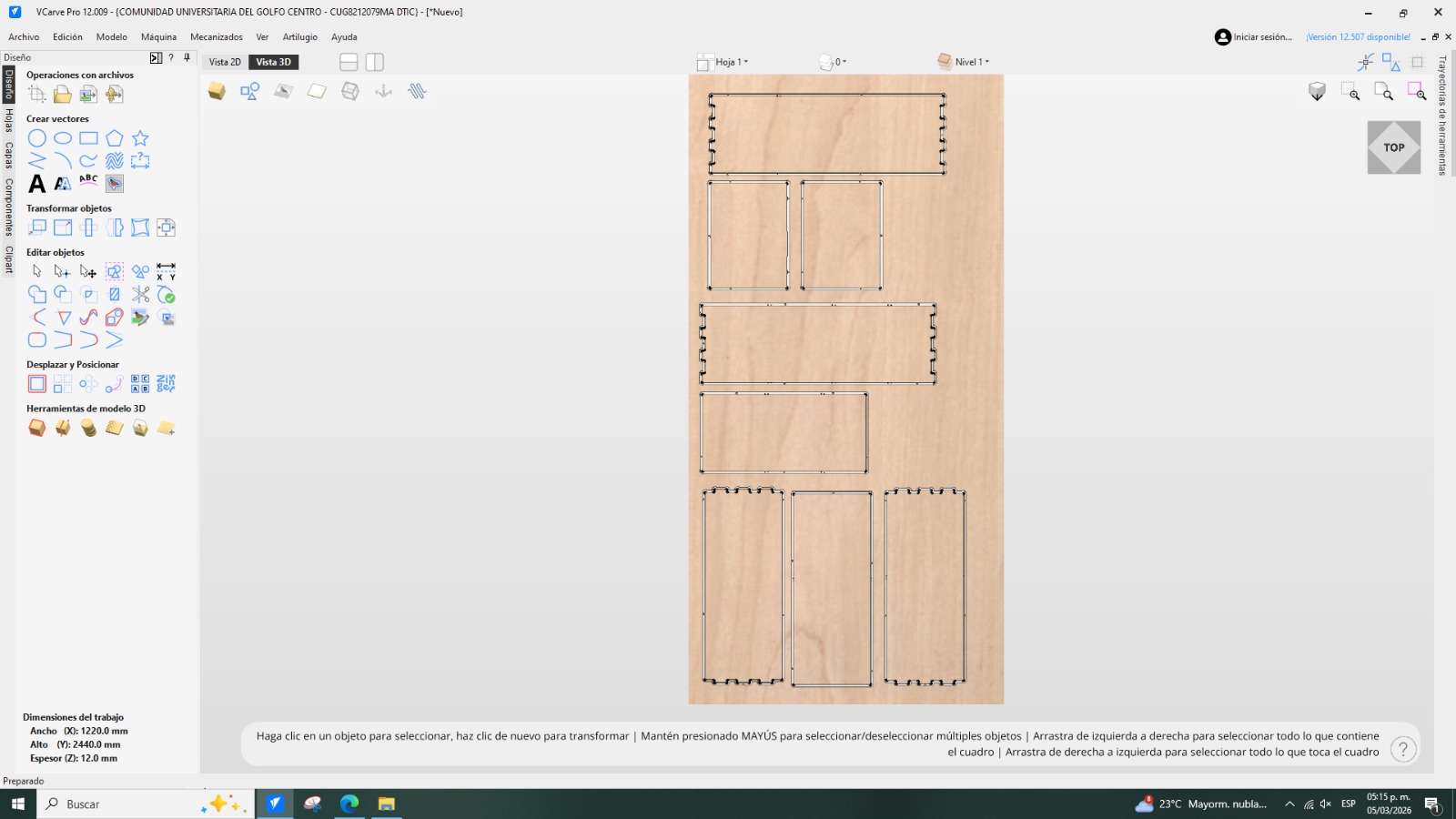
- As a recommendation, I created chamfers in areas where the machine needed to perform 90° cuts. This helps reduce machining difficulty and minimizes potential cutting errors when using the router. For the chamfers, I used a 3.4 mm value and selected a “dog-bone chamfer,” which allows the creation of internal reliefs so that slotted parts can properly fit together.
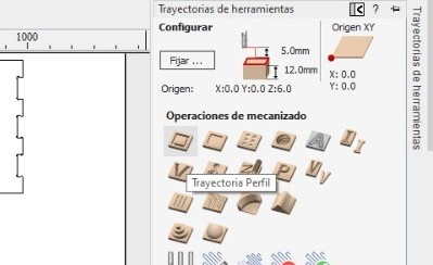
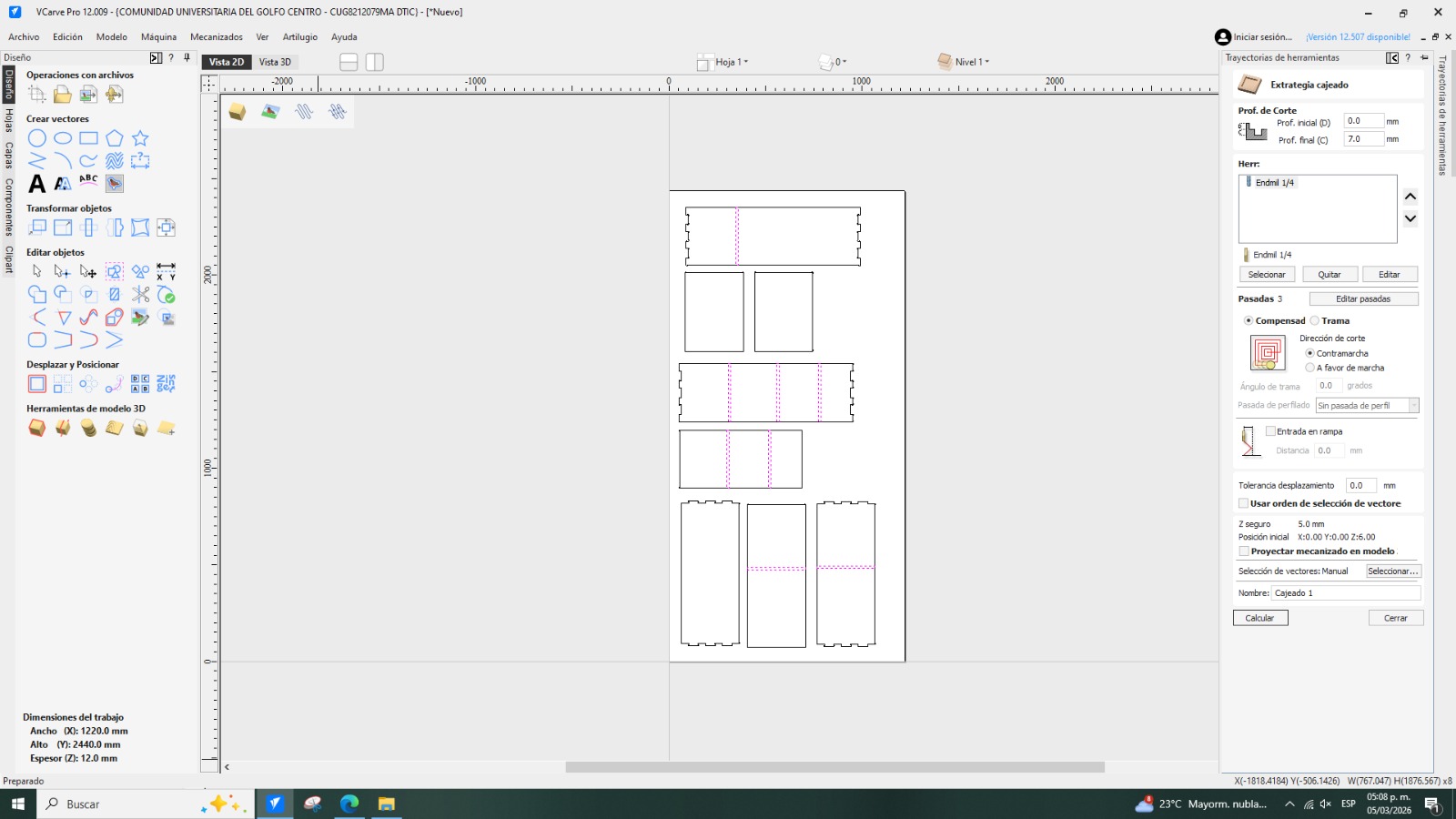
- Once the chamfers were created, I selected the vectors where I assigned the Profile Toolpath (the first option responsible for cutting the pieces).
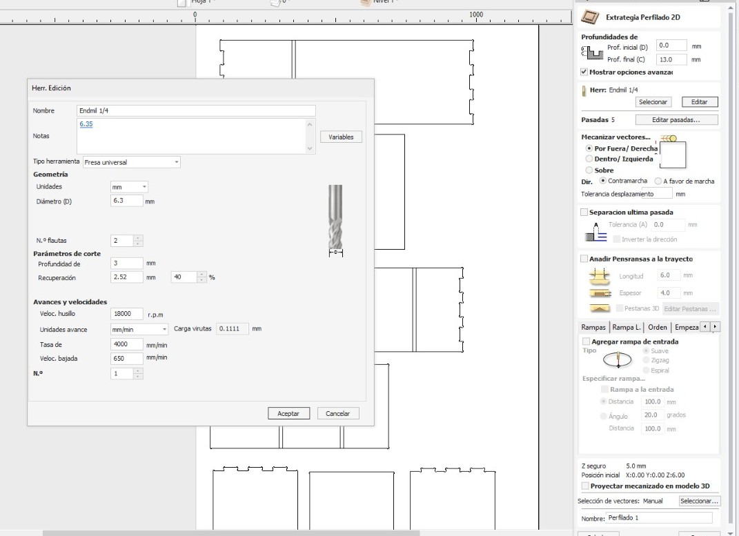
- A window immediately opens where I can configure the tool type and its corresponding parameters. These calculations were made using this cutting calculator, which helps determine the appropriate speed for performing the cut.
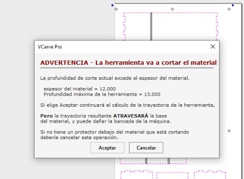
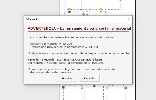
- Once these parameters were assigned, the number of passes was five, with the toolpath set outside the vectors and a cut depth of 13 mm. A warning message appeared indicating that the cutting depth exceeded the material thickness; however, in my case I accepted it.
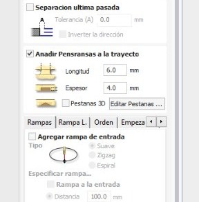
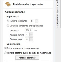
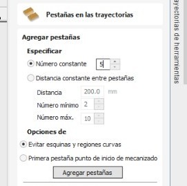
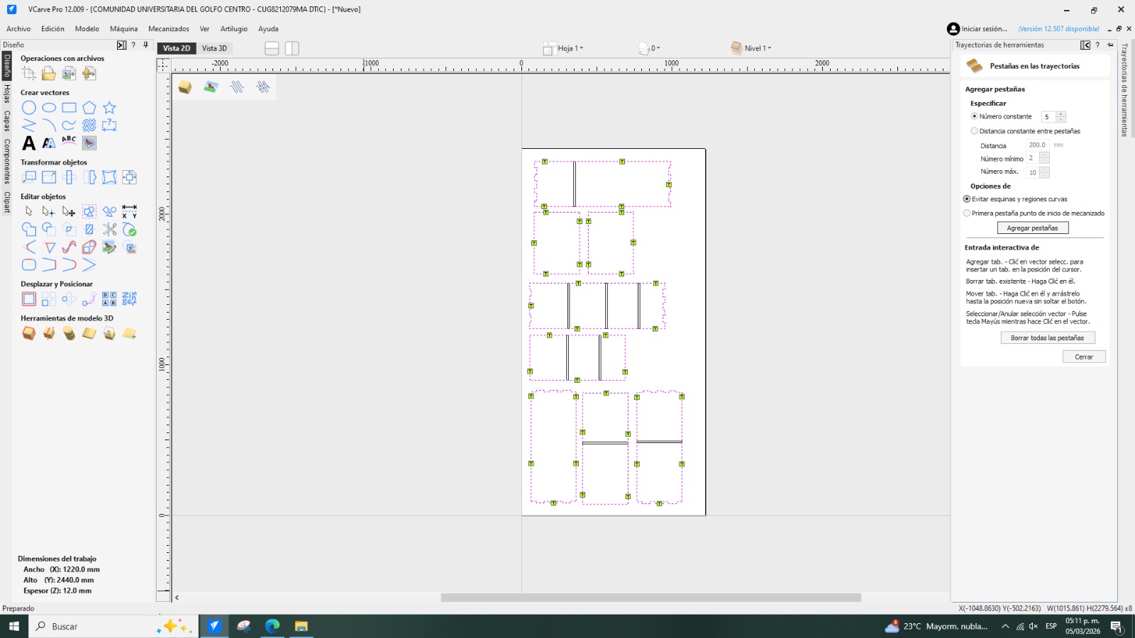
- I also added tabs along the toolpaths to prevent the pieces from moving or jumping during the cutting process. I placed five tabs along the vectors.
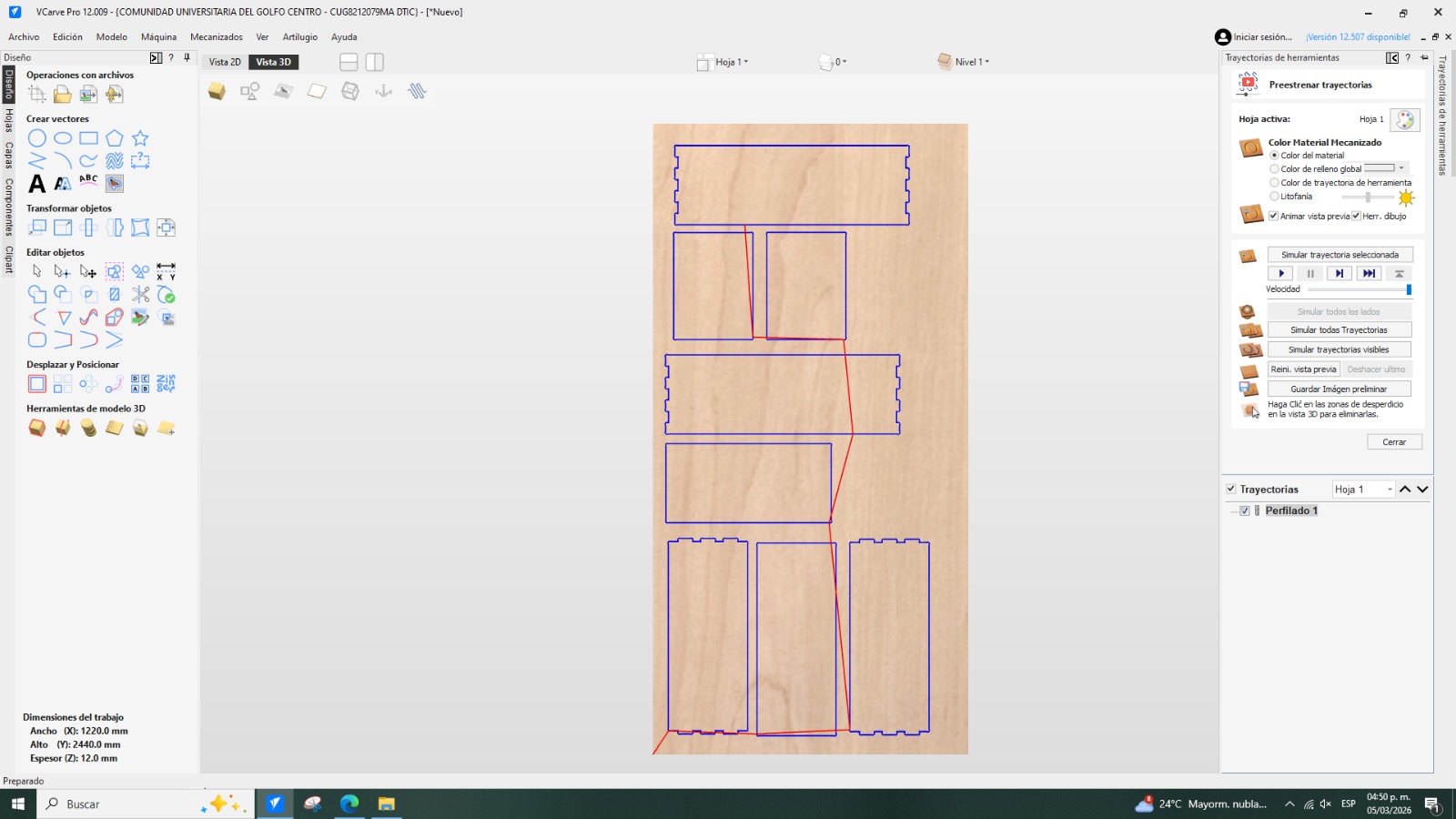
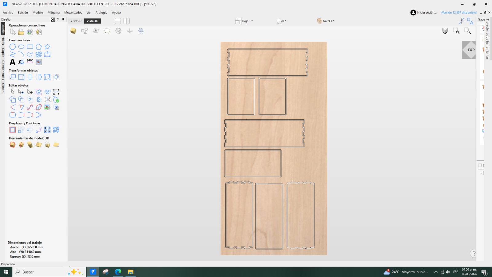
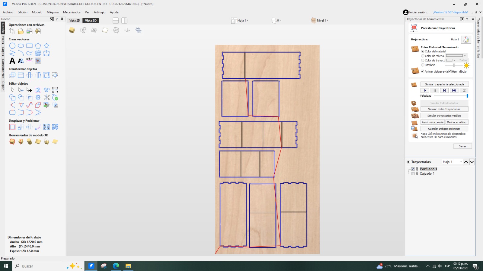
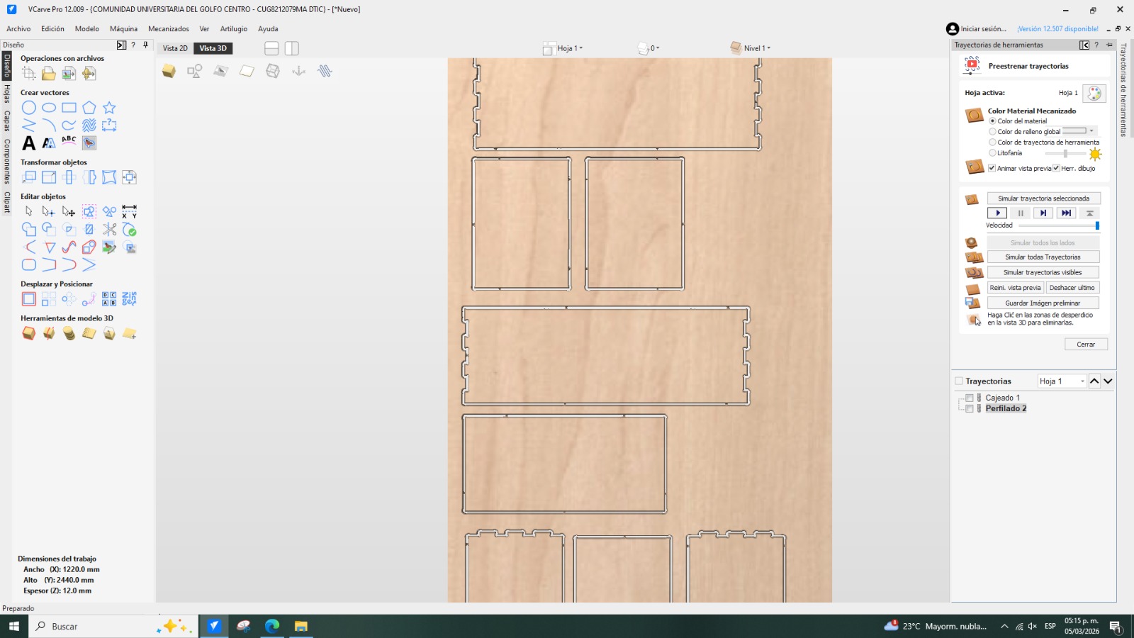
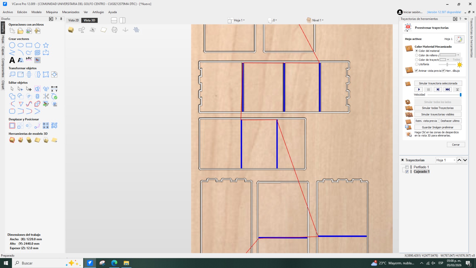
- After this, a window opens where the cutting simulation can be visualized.
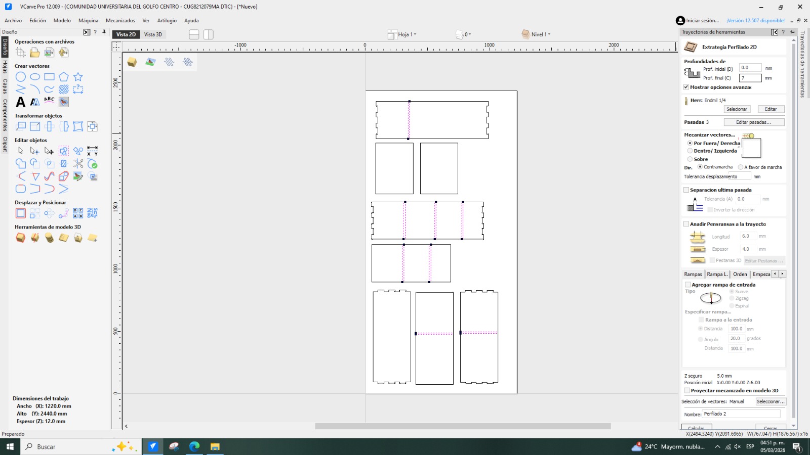
- Next, to perform the remaining cuts required for my type of joint, I used the 2D Profile Strategy, selecting the vectors where this type of assembly was needed.
- I assigned the expected depth value and calculated the toolpath. It is important to note that during this process it is not necessary to manually calculate the kerf, since the program automatically accounts for it.
- Finally, I saved the two generated toolpaths separately for the Asiarobot machine.
| Parameter | Value |
| Units | mm |
| Diameter (D) | 6.3 mm |
| Number of flutes | 2 |
| Depth of cut | 3 mm |
| Step-over | 2.52mm |
| Spindle speed | 18000 r.p.m |
| Feed units | mm/min |
| Feed rate | 4000 | mm/min
| Plunge rate | 650 mm/min |
It is important to remember that the cut must be balanced: the machine should not move so fast that it breaks the tool, nor so slow that it generates excessive heat or even a fire. The values I used are shown below.
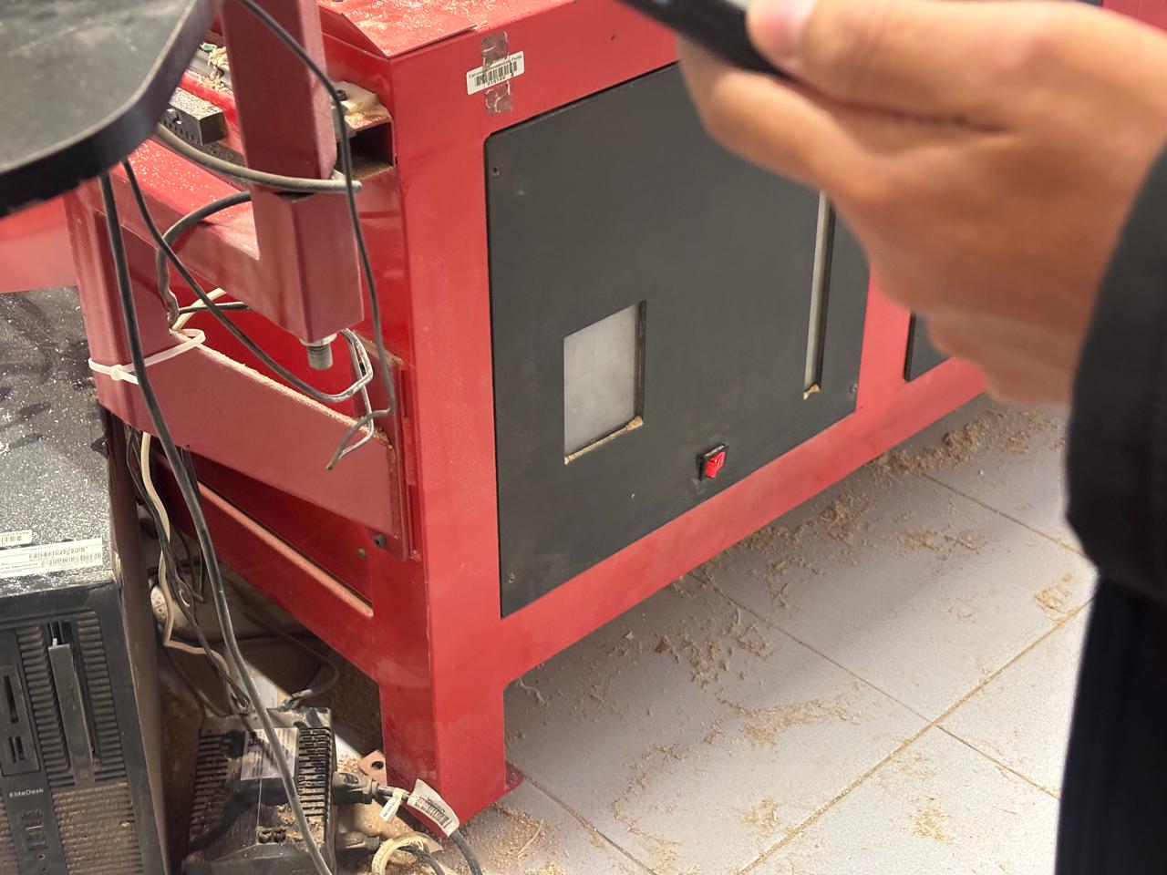
Using the March Machine
The use of this machine is very simple. To turn on the machine, you just need to activate the switch located underneath it. Then, once you have the .txt file (saved on a USB drive), the drive is inserted into the computer.
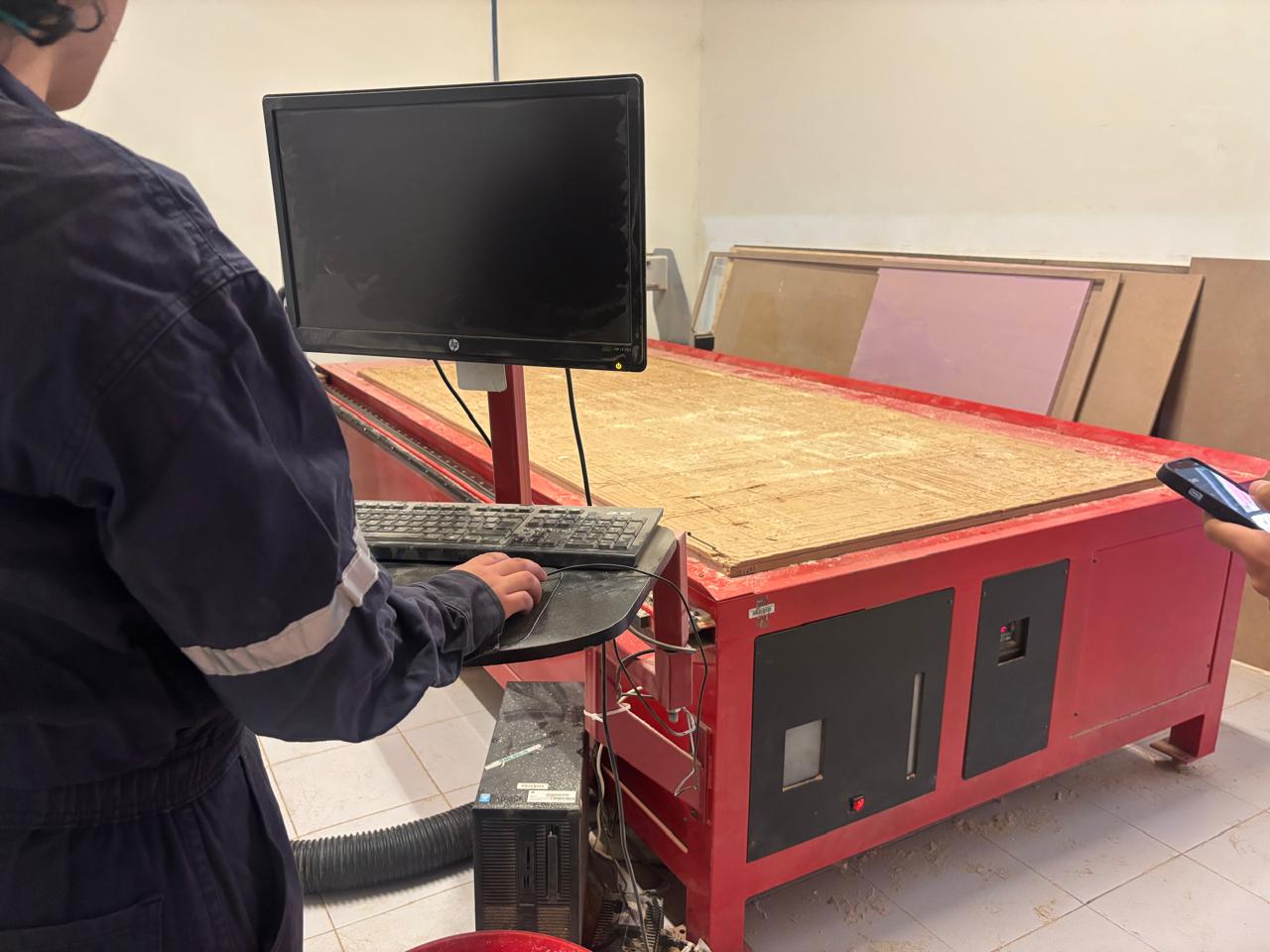
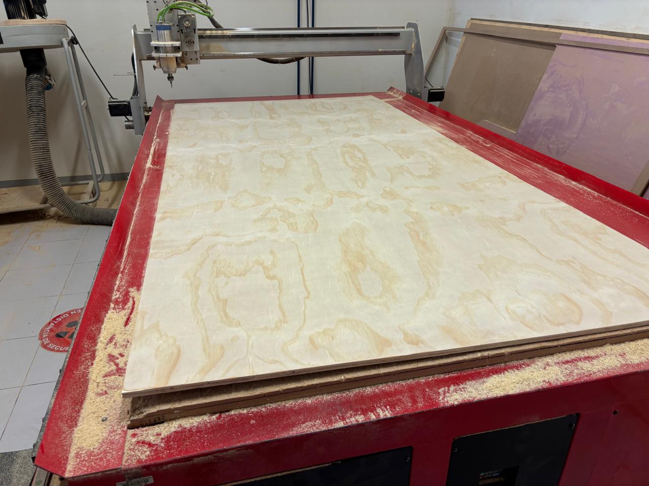
The work material must be placed on the machine. It is important to know that the wood needs to be nailed down to prevent it from warping or moving while the cut is being made.
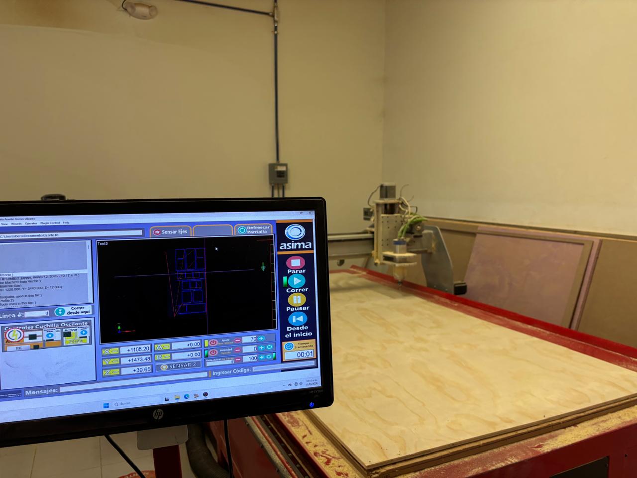
Once the previous step is completed, the corresponding program to perform the Mach3 CNC cut is opened. Then, the file is opened and the G-code is loaded into the machine. The interface will display the cut that will be performed.
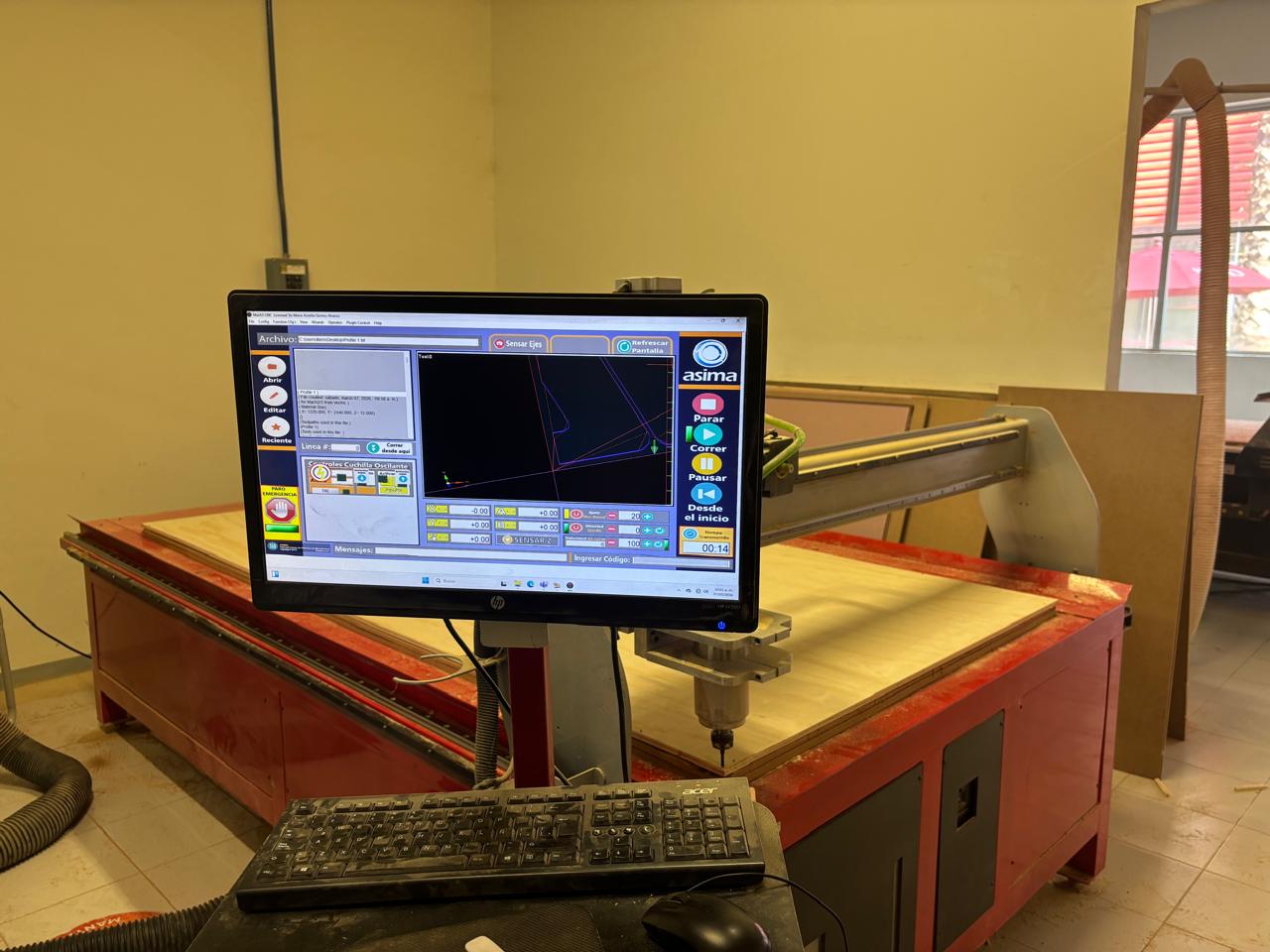
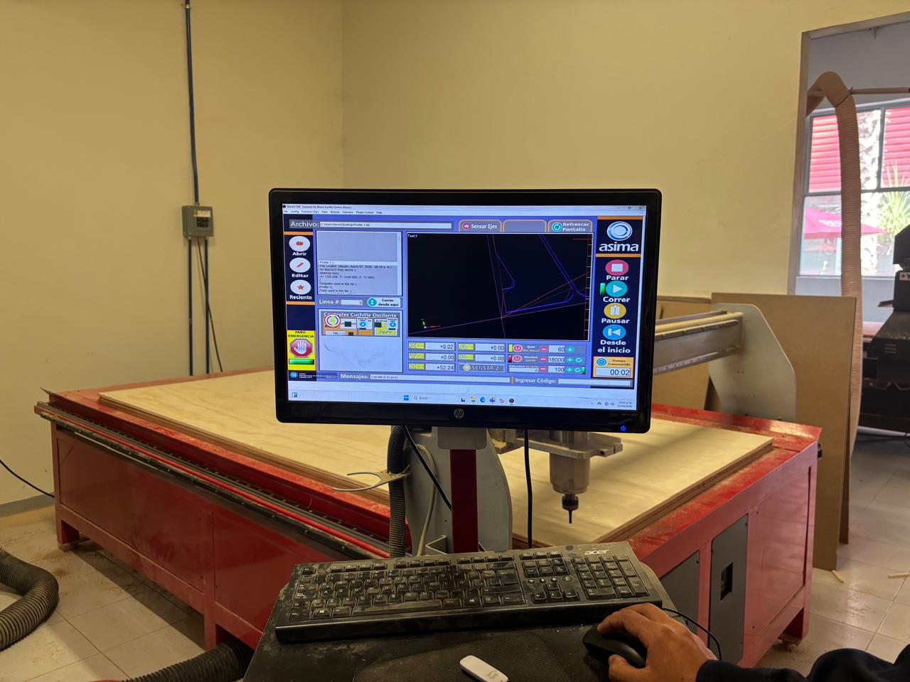
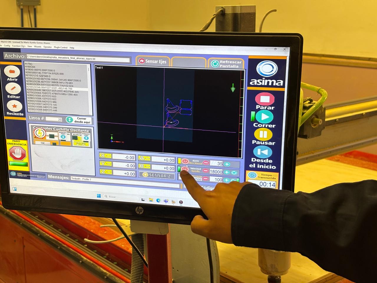
The origin is set by moving the tool axis to the corner of the material, and the tool speed is assigned. Finally, the ASIMA program is opened on the computer, where the .txt file is opened. Then, to verify that the tool does not pass over the screws, I moved the tool over them and compared the trajectory. Once this was verified, I started the program.
How to configure the Z axis?
Using the menu of the software (left side), raise the Z axis to the desired height and center it over the material. After that, lower the Z axis unit it touches the material. In this way, you can click origin or -Z to establish the origin.
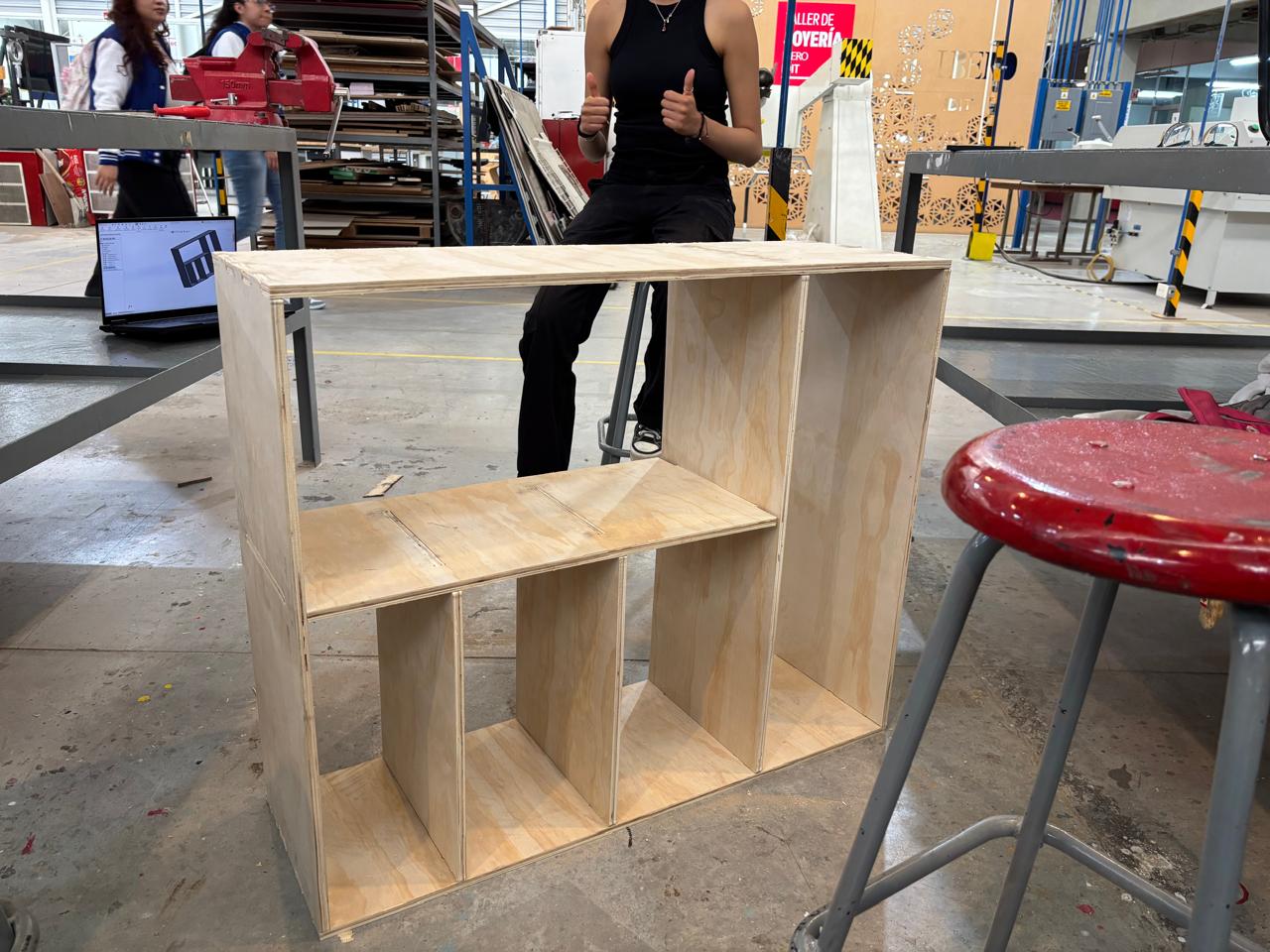
Once the cut was completed, the work area is cleaned and the remaining boards are removed. Finally, I assembled the parts.
For my fixings I used a hammer to fit the furniture more firmly because the furniture design was made to be joined by assembly. In the next video you can see the process:
Final Result
And, this is the final result of my work for this week.
Conclusions
It is important and necessary to consider safety measures to carry out this type of work. Likewise, knowledge acquired in previous weeks was applied. It is important to learn how to use this type of machine, as they constitute a fundamental part of the production of future projects. Finally, it is important to consider the type of material, speeds, and tools used when setting the parameters. It was highly enriching to create this design, as what was learned was applied in something useful.
If you want to access to my work from this week, please click here to download!
Finally, for the group assignment for this week, you can find the information here