Computer Controlled Cutting
Individual assignments
- Design, lasercut, and document a parametric construction kit, accounting for the lasercutter kerf.
- Cut something on the vinyl cutter.
Laser Cutting
To perform laser cutting of parts, it is necessary to use software that allows exporting files in DXF format. For this purpose, I used SolidWorks, where I designed the main parts for my assembly. In total, I created two assemblies: one consisting of a box structure and another in the shape of a cat.
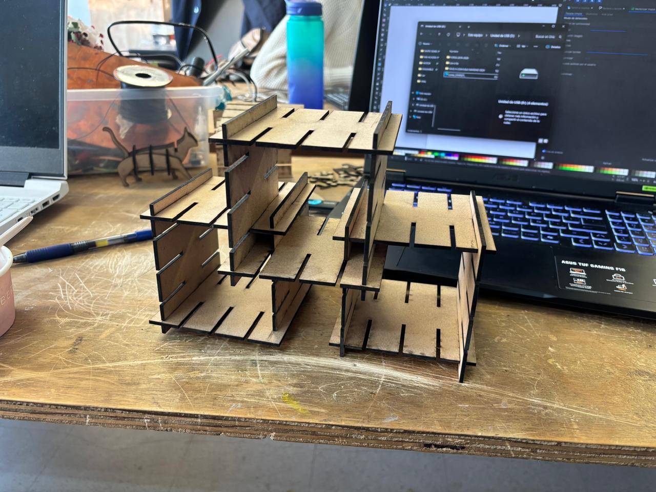
Box Structure Design
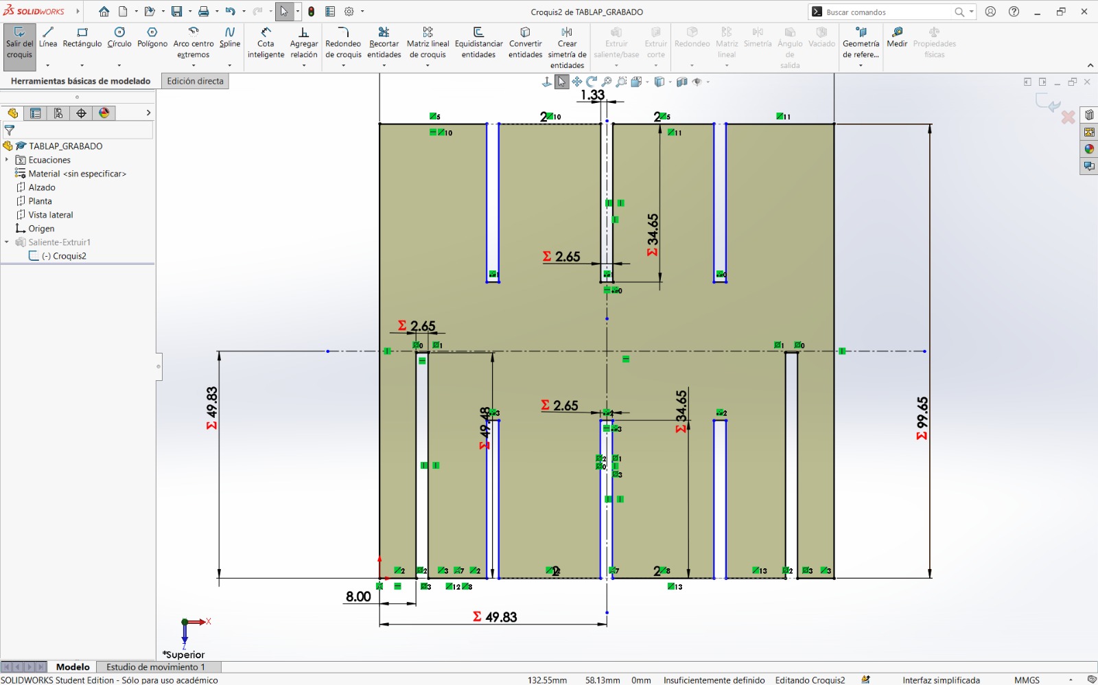
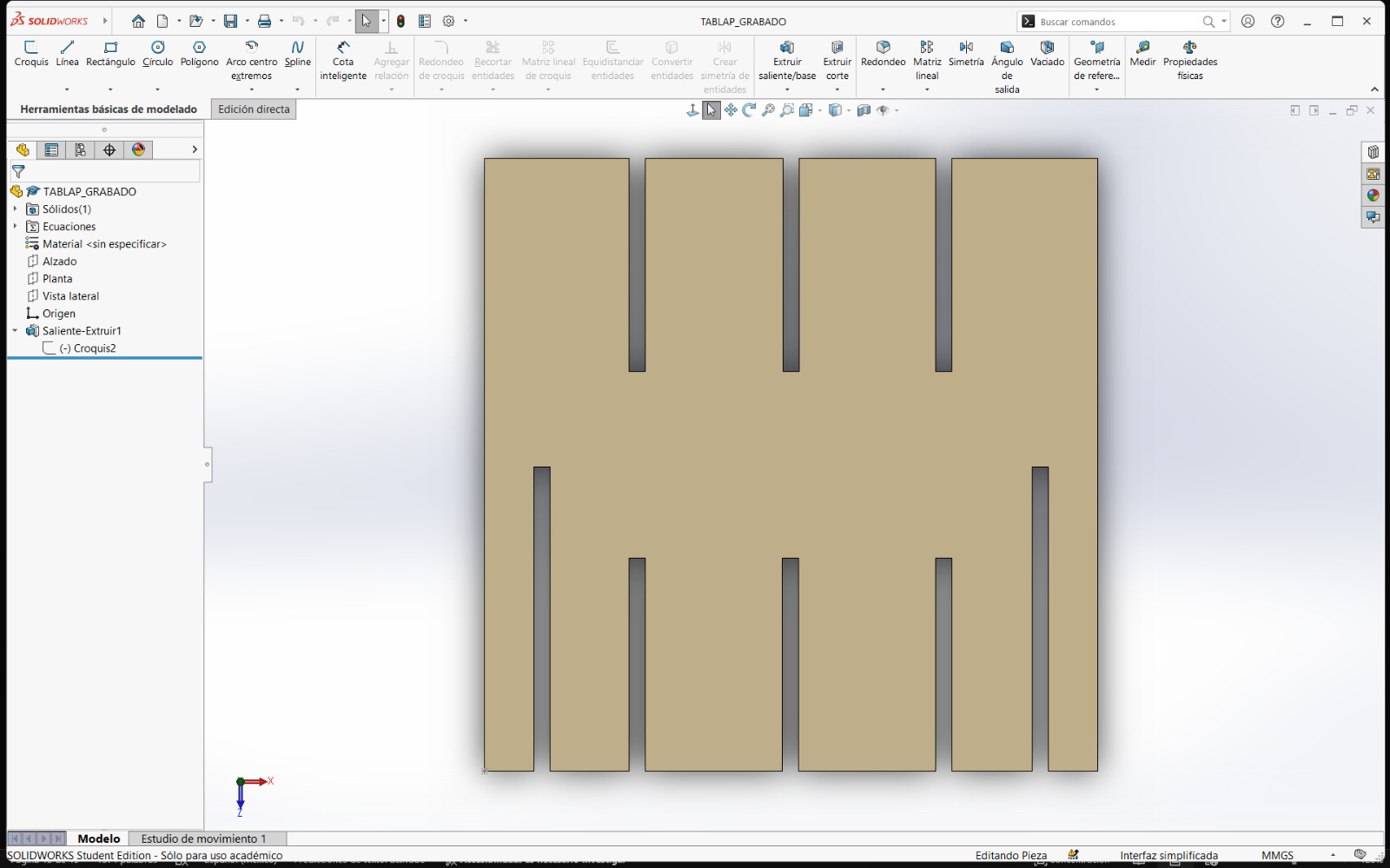
In the case of the box structure, I designed a square part in which each dimension was parameterized using the equations provided by the software. Parameterizing dimensions allows the use of variables that are easily accessible and facilitate design changes.
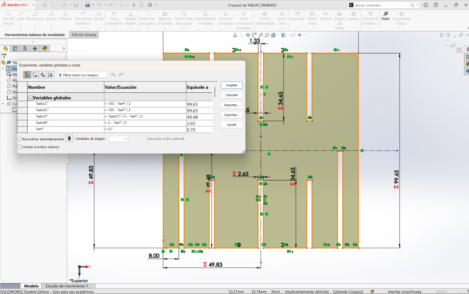
How to Create Parametric Variables for Dimensions?
When creating an element using the Smart Dimension tool, instead of entering a fixed value, an equals sign (=) is typed, followed by the variable name, and then pressing Enter. In this way, the variable is registered and can later be assigned a specific value within the Equations section of the design tree.
Steps Followed
- A sketch was created, and a rectangle was drawn. The Smart Dimension tool was used to define the parametric dimensions.
- It was important to include the kerf value within the equations. To account for this, I modified each variable by subtracting half of the kerf value from the established dimensions.
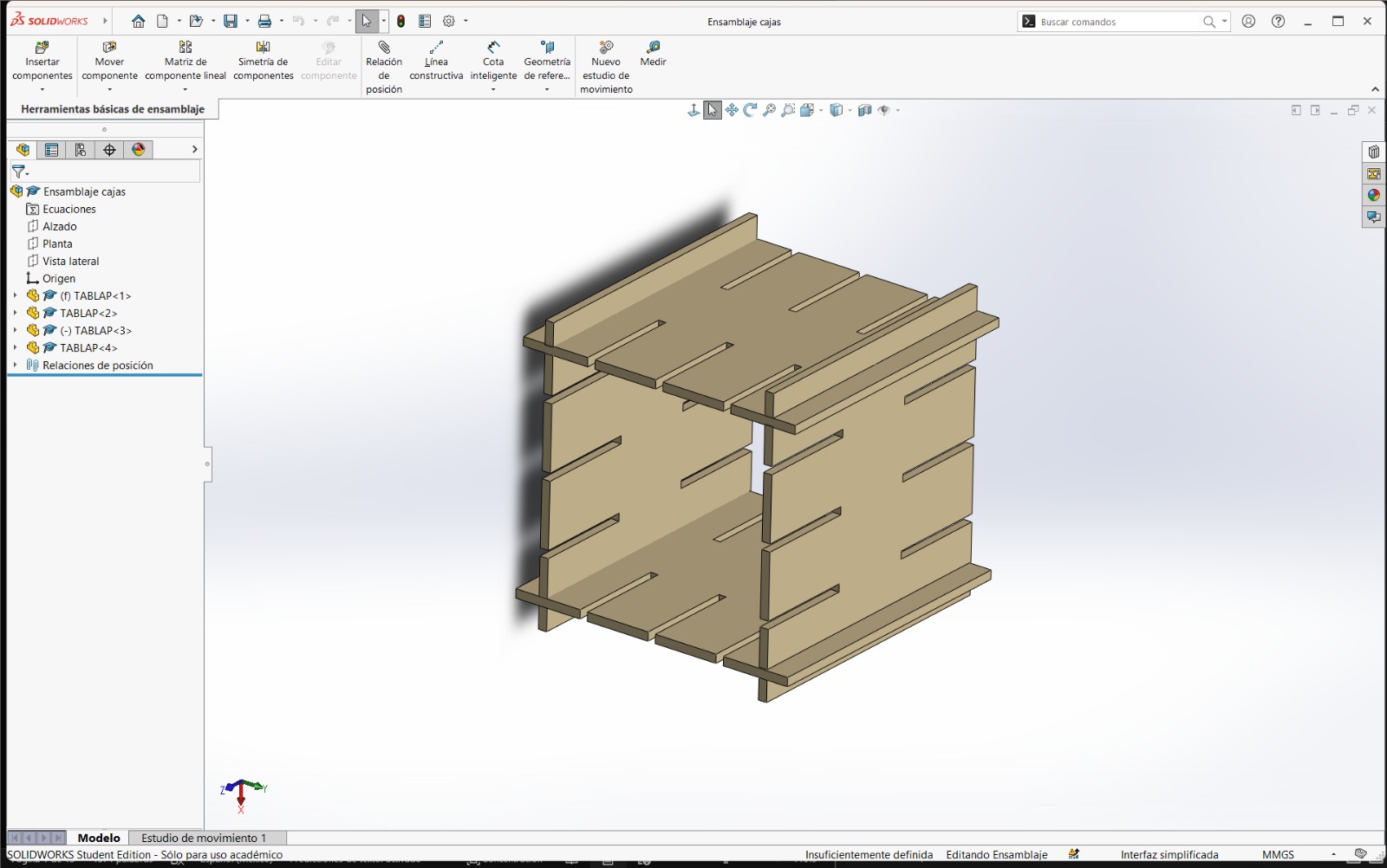
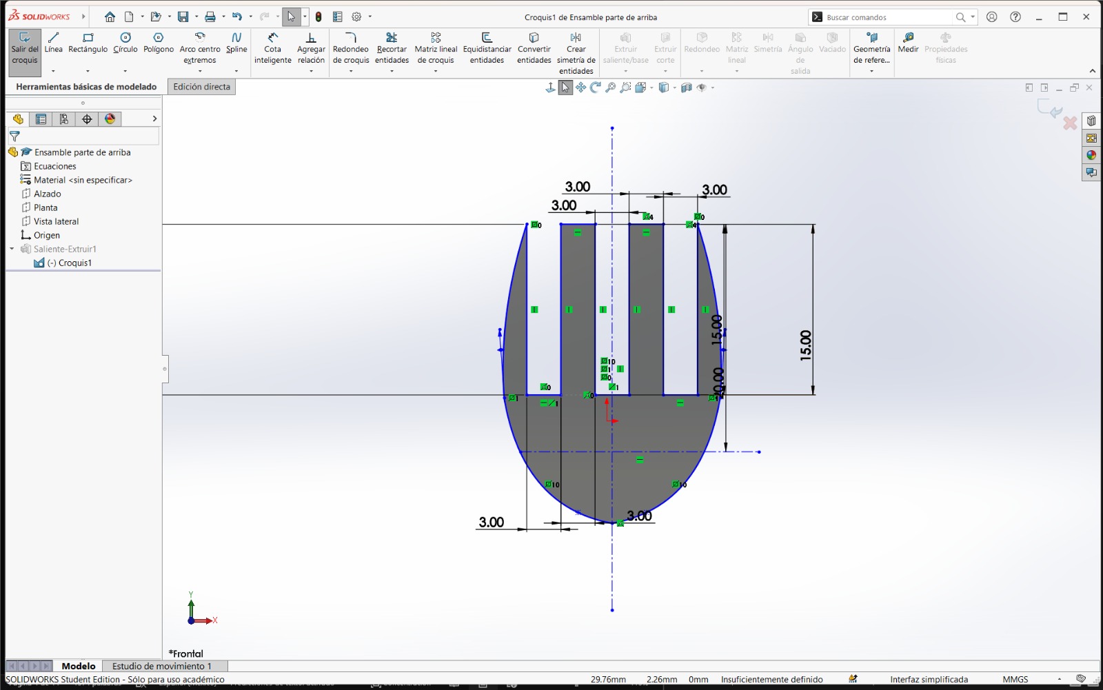
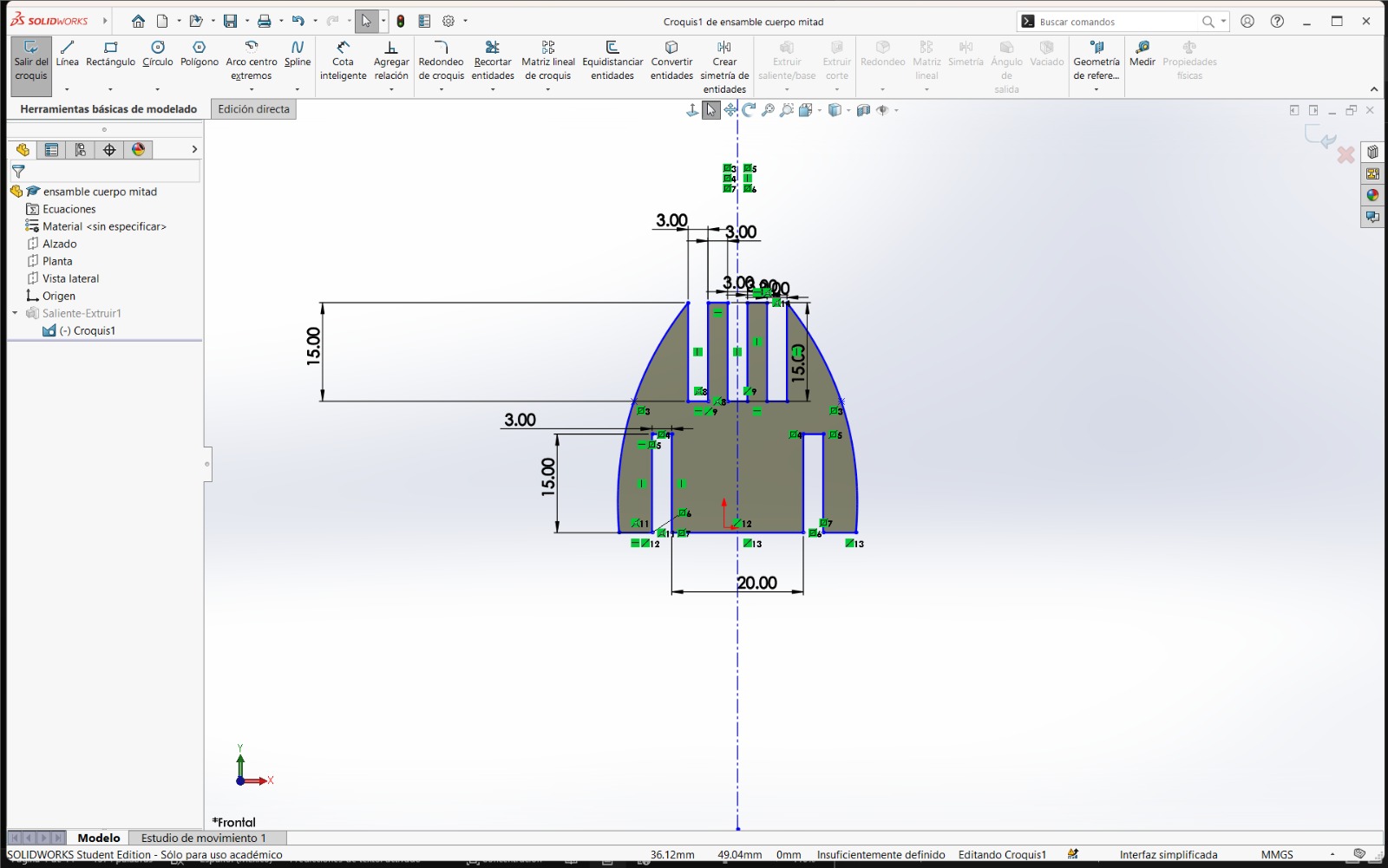
- Since I wanted to create a press-fit joint assembly, rectangles were drawn and excess lines were removed.
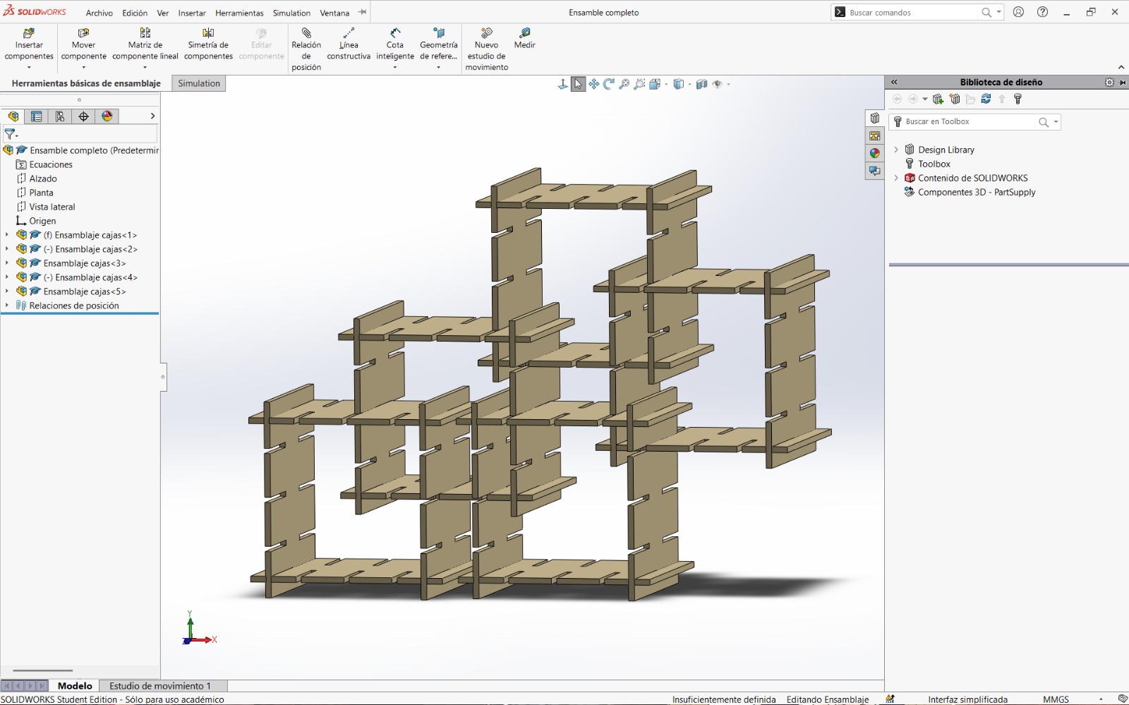
- The design was extruded using the thickness of the material. Finally, in an assembly document, the parts were placed and assembled to obtain a visual representation of the final result.
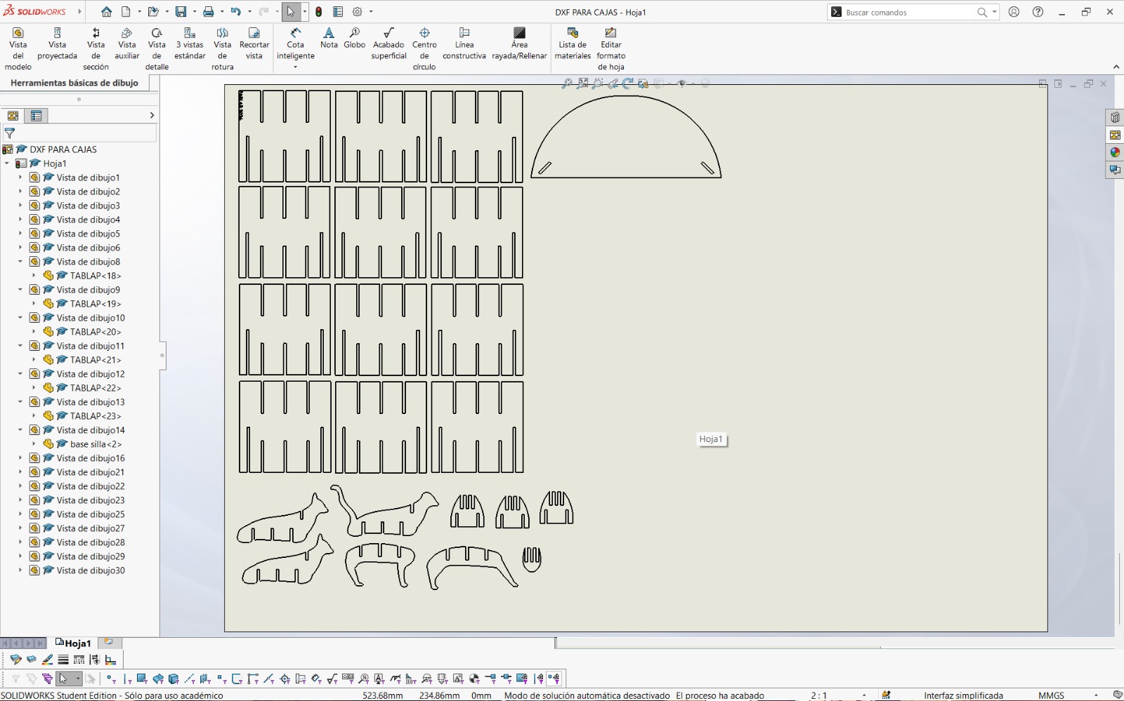
- To cut the parts using the laser machine, the designs had to be exported as DXF files. To do this in SolidWorks, the following steps were followed: File → Make Drawing from Part. This opens a format where views of the parts can be placed according to the required cutting orientation. I personally preferred exporting the parts this way because it allowed me to include multiple pieces within the same file.
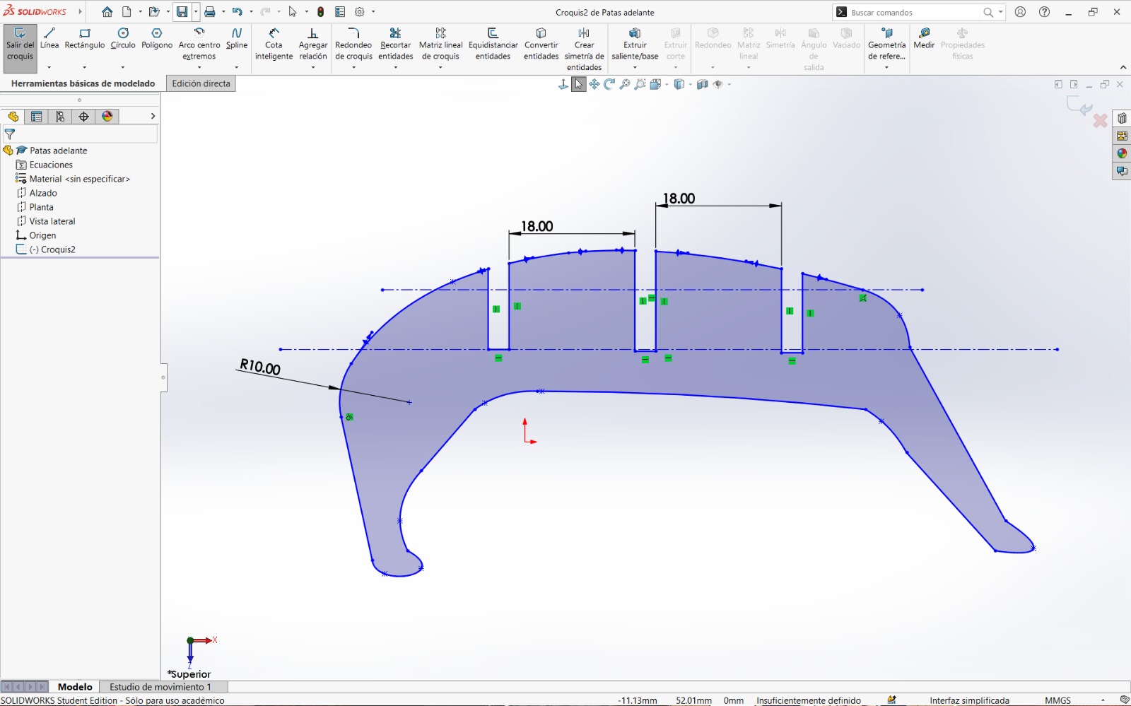
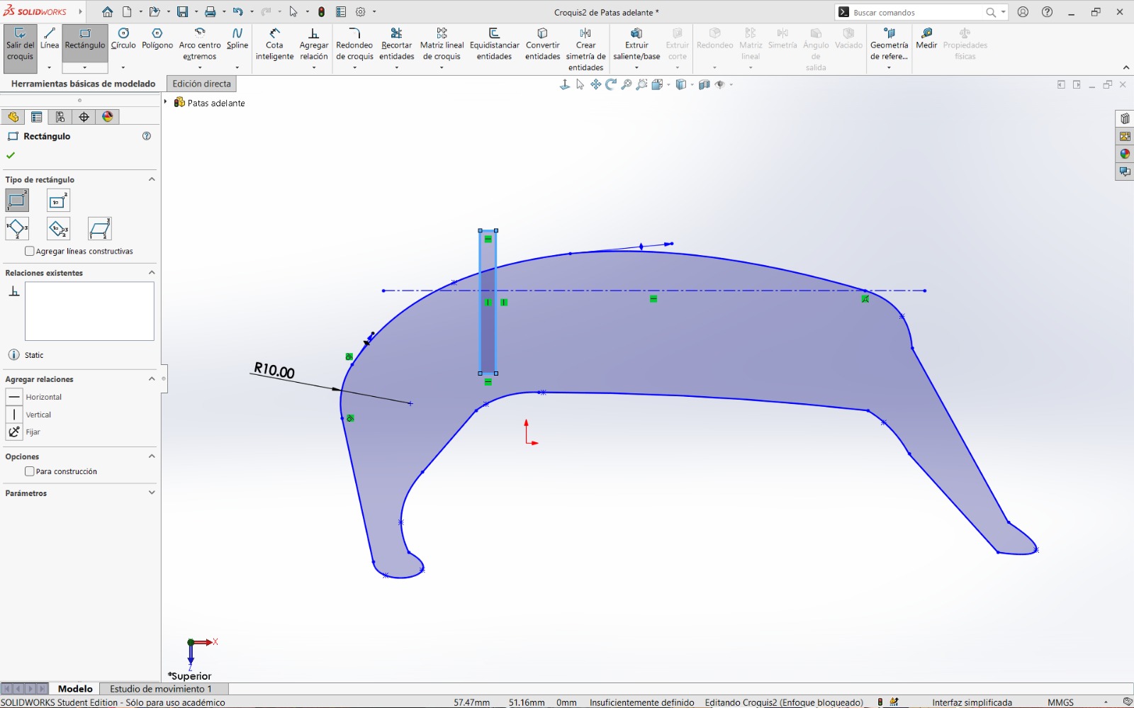
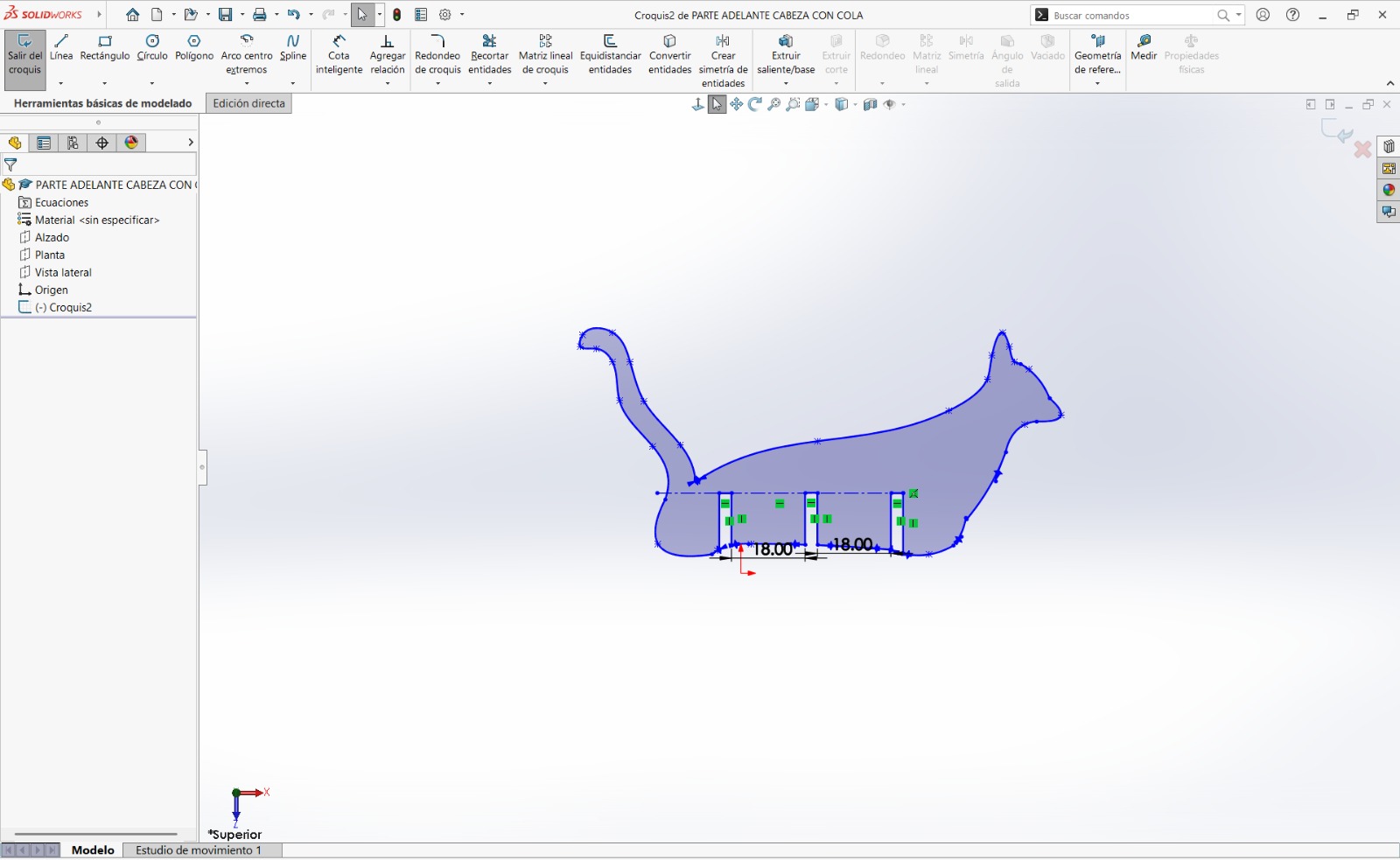
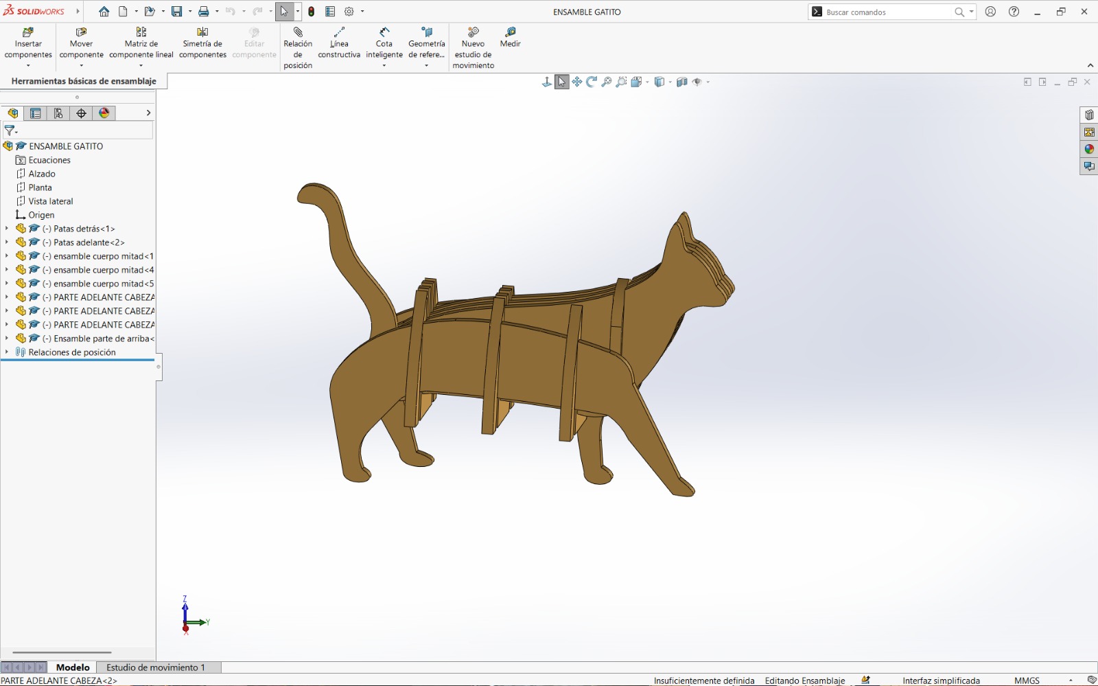
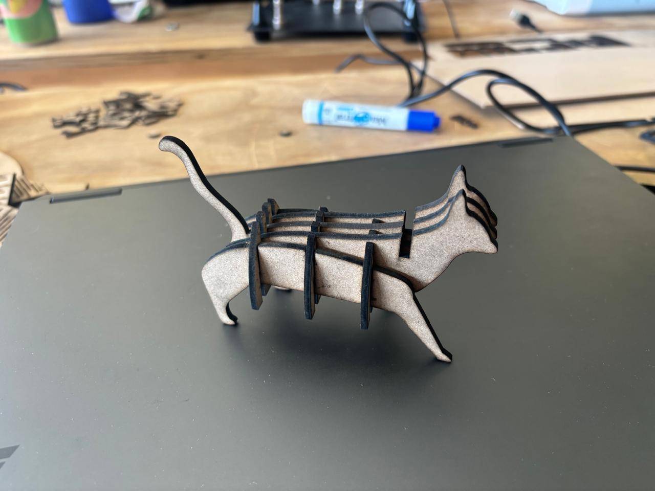
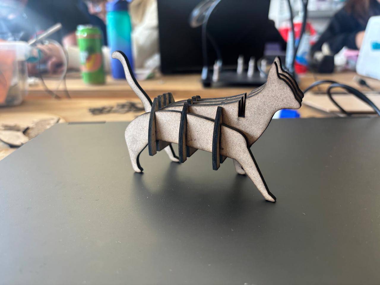
- Finally, I created another assembly in the shape of a cat and repeated the same process described above.
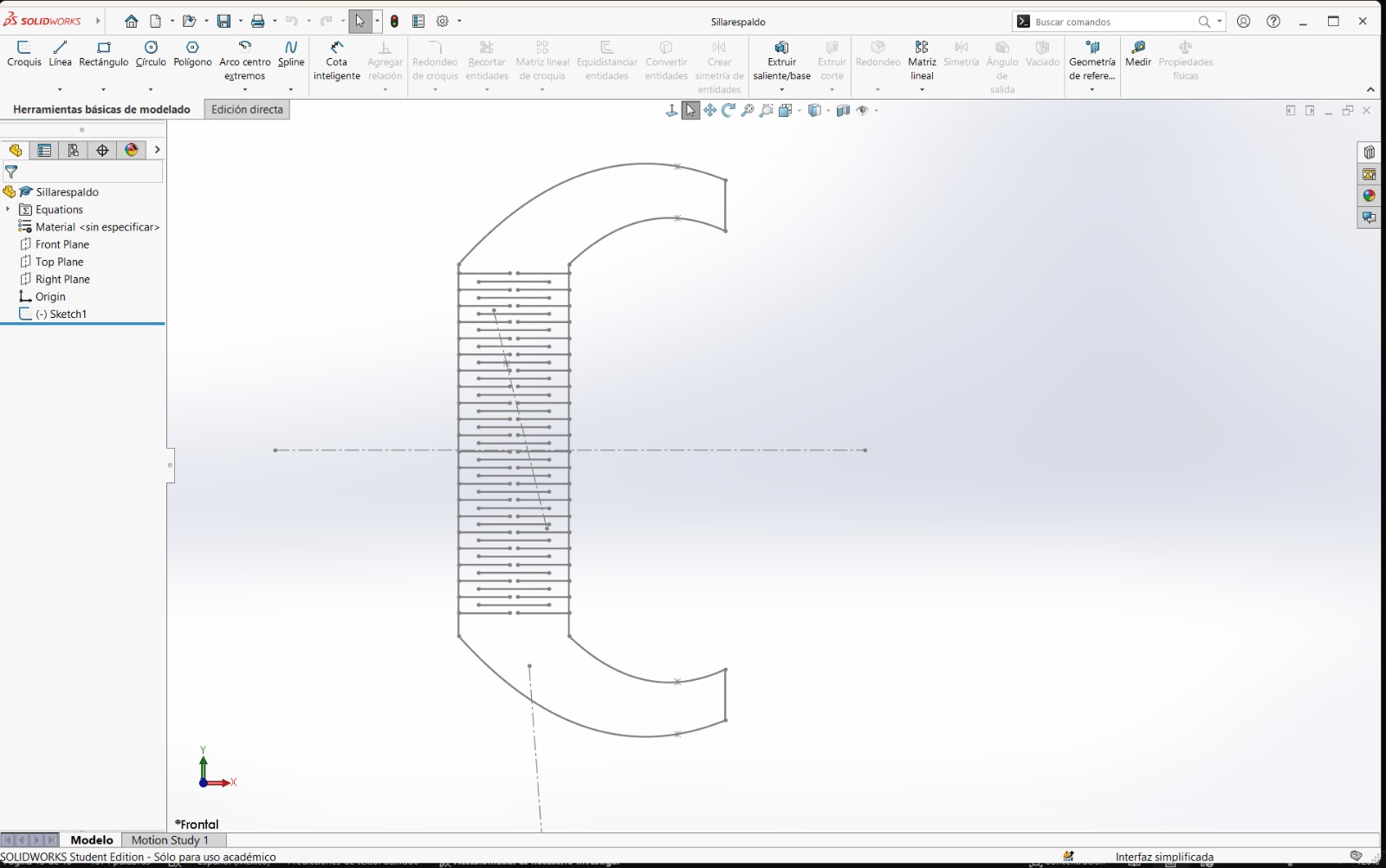
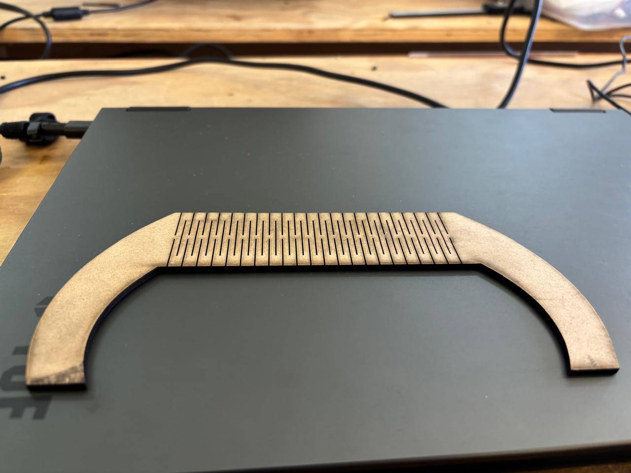
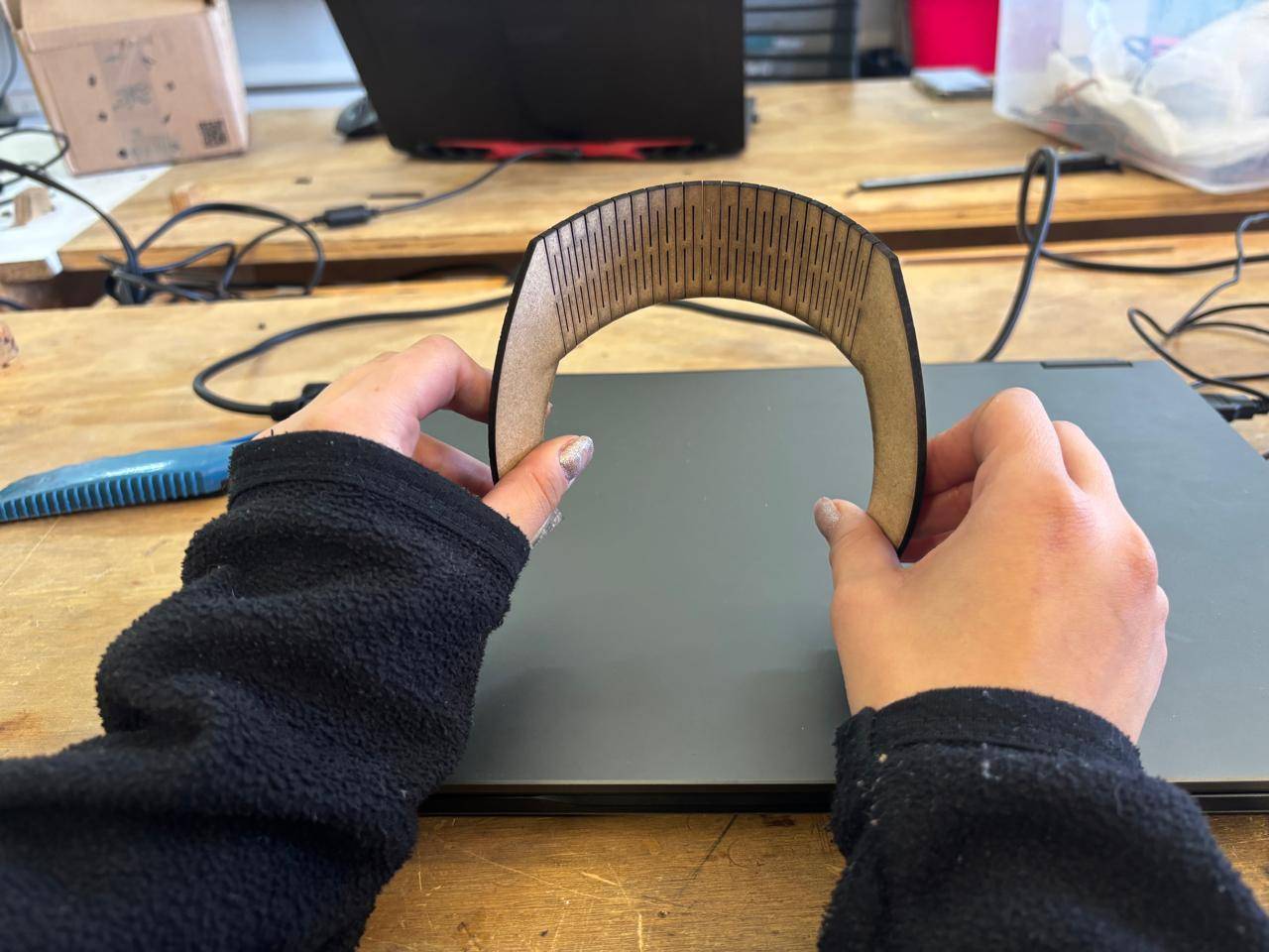
- To design the living hinge, my instructor provided this template, which served as a reference. Modifications were made using the predefined equations. Specifically, I modified the first three ranges to define the material thickness, kerf value, and the desired bending angle. The rest of the design was completed afterward.
What is Kerf?
Kerf refers to the width of the slot generated by the laser cut. There are several techniques to calculate it. In this case, test cuts were performed, and based on the measured distance between the spacing left in the cut and the number of cuts made, a kerf value was obtained. This value was then used to design the square shelf structure.
Another Way to Export Files
From the part file itself, the design can simply be saved as a DXF file. A dialog window will appear, allowing the user to select which views to export.
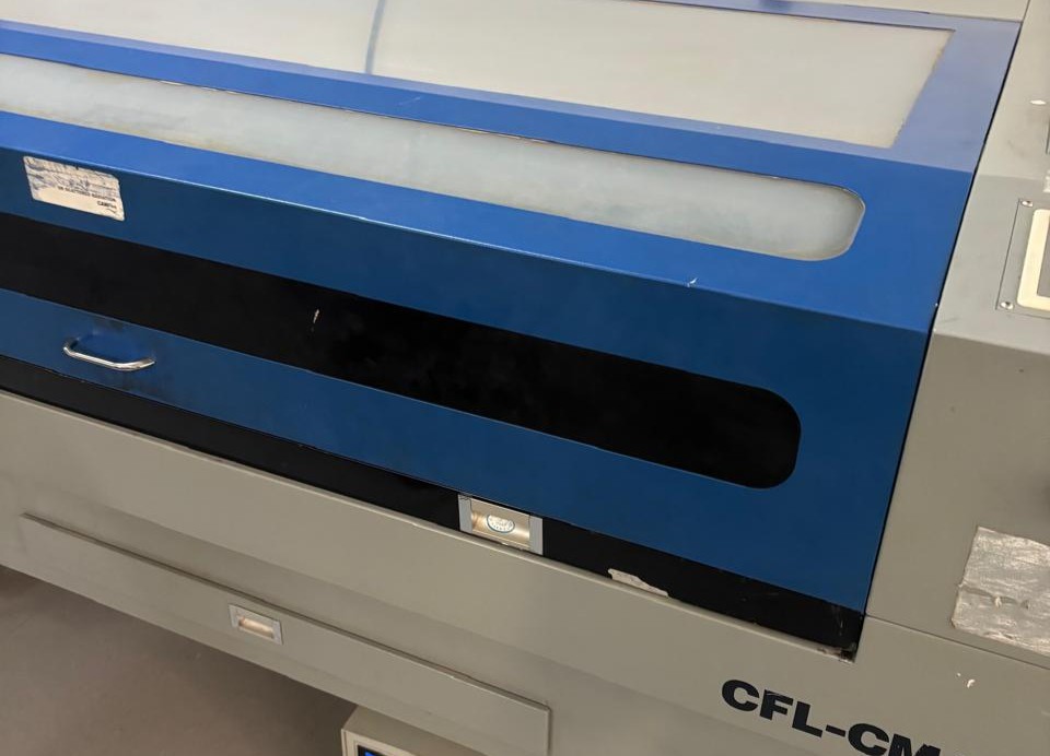
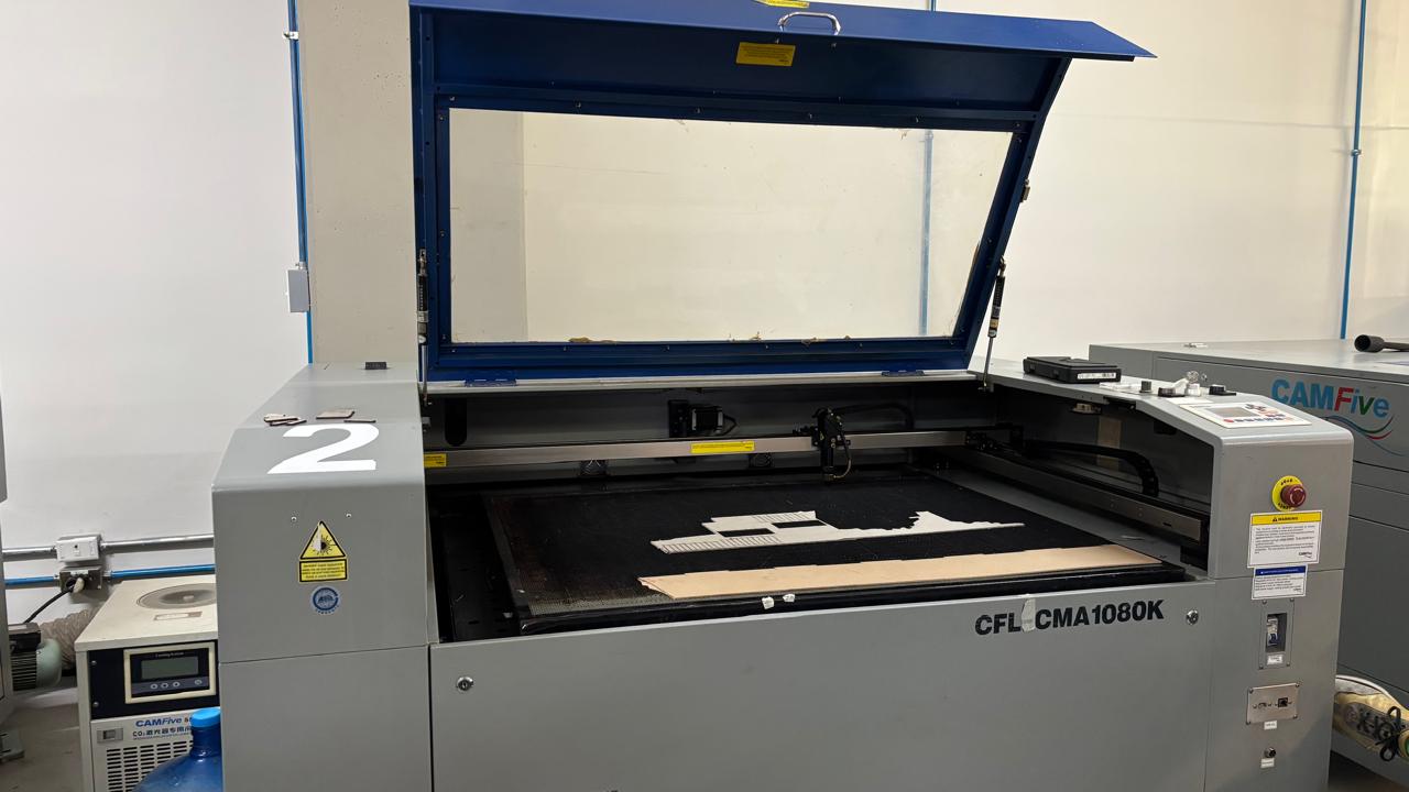
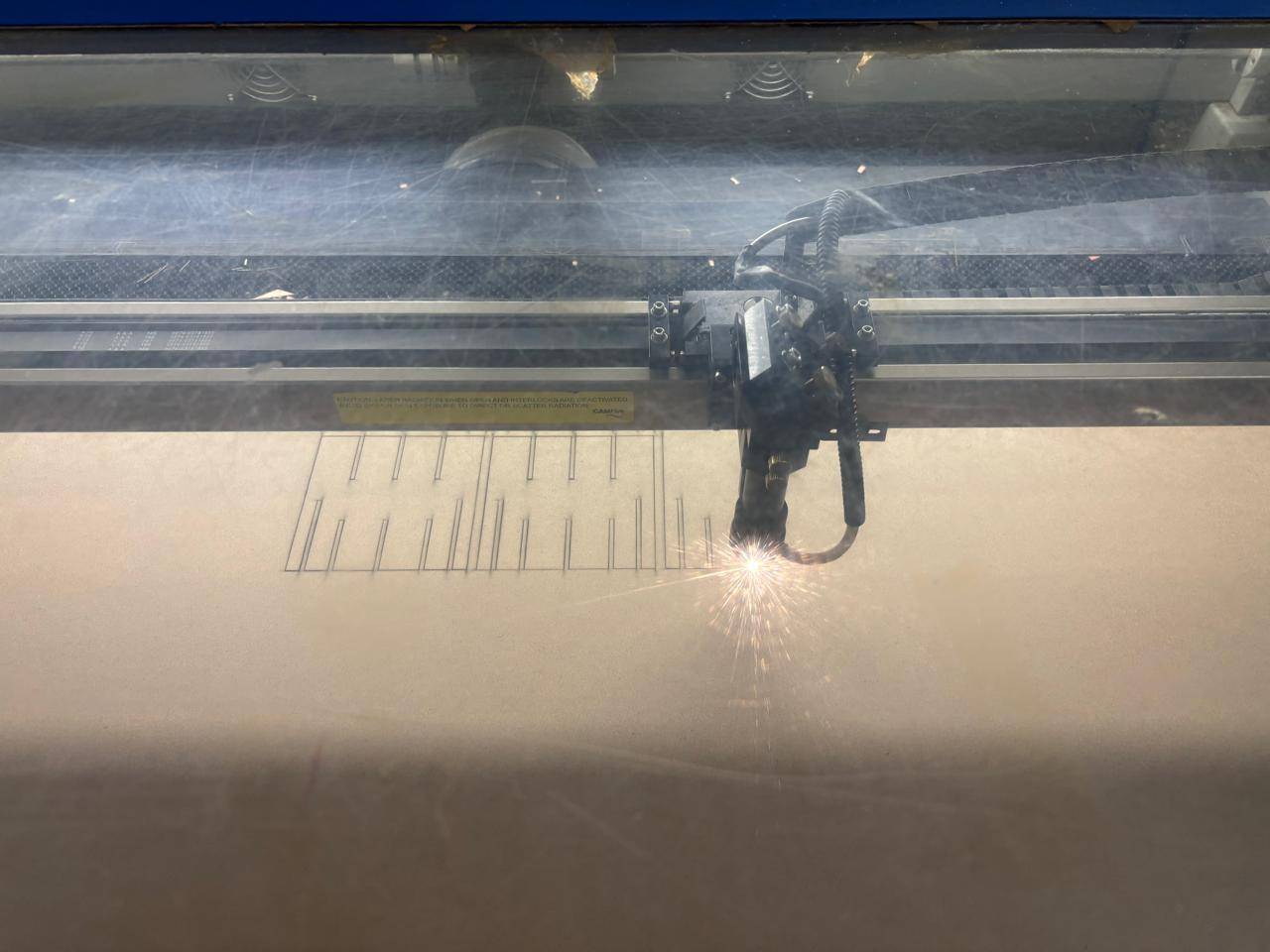
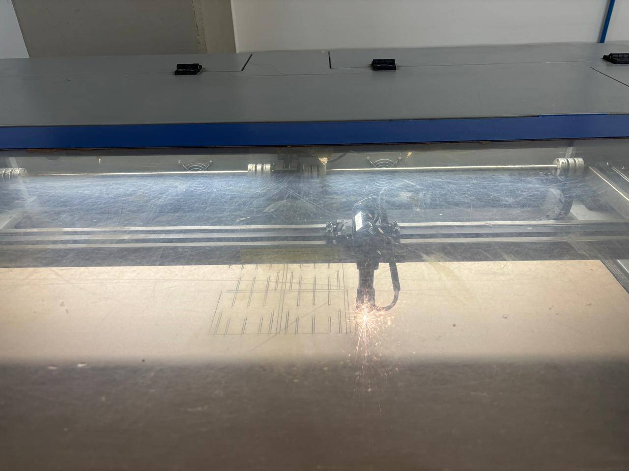
Laser Cutting Process
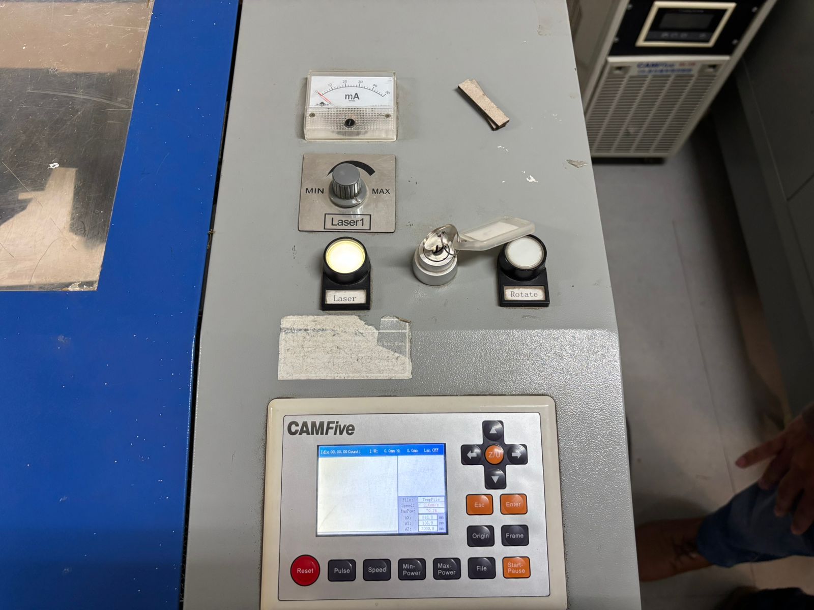
To use the laser machine, I was provided with a safety key to activate the machine and a USB drive containing the cutting software. First, I connected the machine to the power source, turned on the main switches, and disabled the emergency stop.
Once this was completed, I used the provided key to activate the laser cutter. This key functions as a safety lock required for operation.
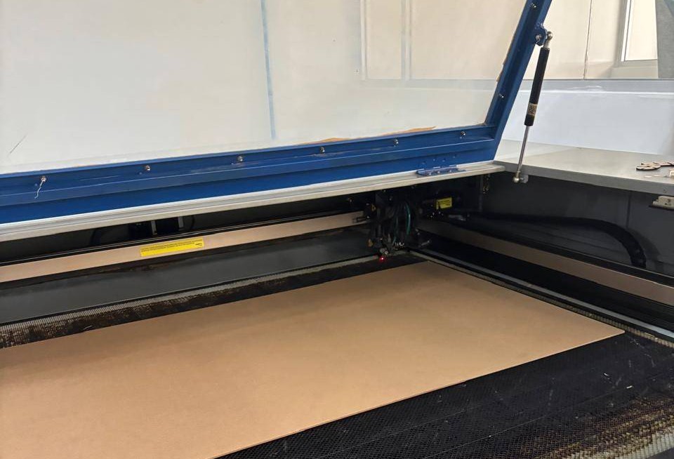
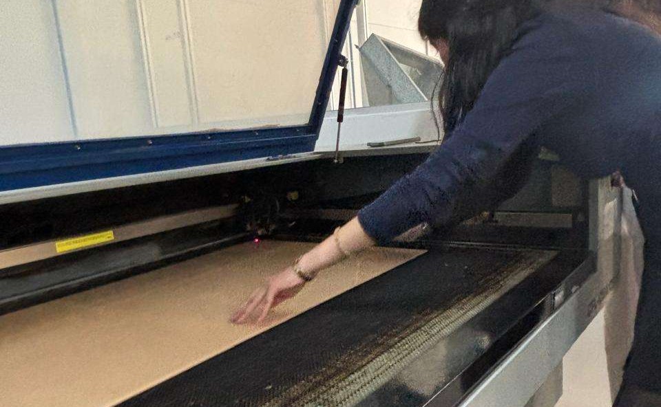
Next, to establish the origin point, I used the arrow buttons to move the laser to the upper-right corner, which is the default and preferred starting point, although the origin can be set anywhere. Then, I pressed the origin button to define the starting point of the cut. To verify the origin, I moved the laser and pressed the Esc button, which should return the laser to the defined origin.
After completing this step, I closed the laser cutter door and inserted the USB drive containing the cutting software, as well as my own USB drive with the DXF files. Within the program, I opened my files and adjusted them according to the desired outcome.
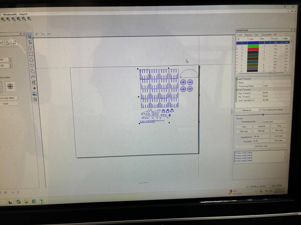
Within the software, it is possible to assign cutting priorities. The first priority is engraving, where the elements to be engraved are selected. Then, by right-clicking on the engraving color and selecting Apply to picked object, those segments are assigned different parameters. For the engraving process, the following values were applied:
| Max. Poder(%) | 30 |
| Min. Poder(%) | 20 |
| Work Speed (mm/s) | 300 |
And the other values:
| Max. Poder(%) | 40 |
| Min. Poder(%) | 38 |
| Work Speed (mm/s) | 22 |
The program also includes an option called Go Scale, which allows visualization of the area that the cuts will occupy. This step is highly recommended, as it ensures that the design fits within the material and prevents potential cutting issues.
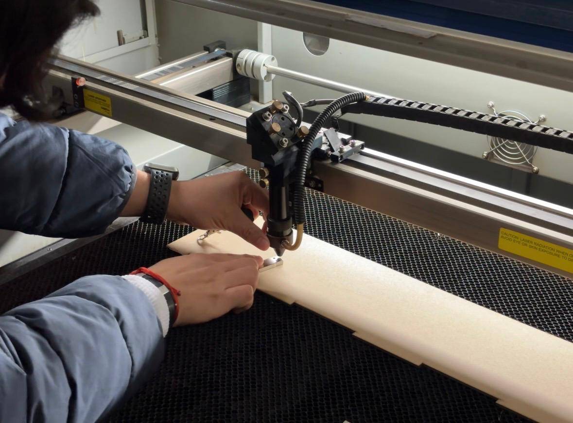
Finally, I increased the laser power and pressed the button to activate the laser beam, initiating the cutting process.
Once cutting was completed, I verified that all pieces were properly cut. The material, pieces, and remaining scraps were removed, leaving the workspace clean.
To turn down the machine, I reduced the laser power and turned off the laser beam. The safety key was removed, the emergency stop was disengaged, and the machine switches were turned off. Finally, the software was closed, and the machine was disconnected from the power source.
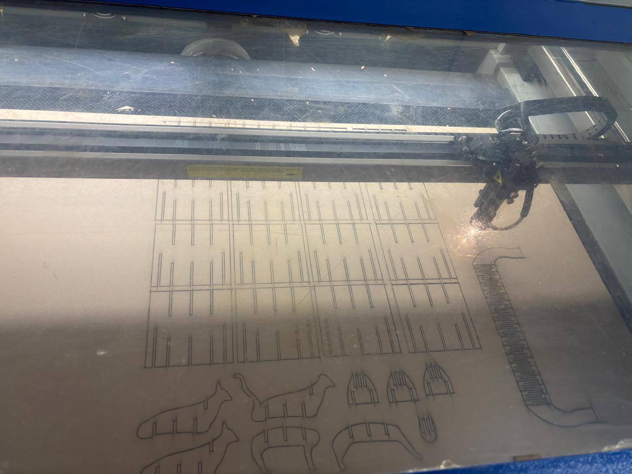
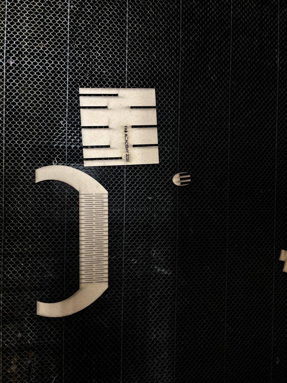
Laser Cutting Results
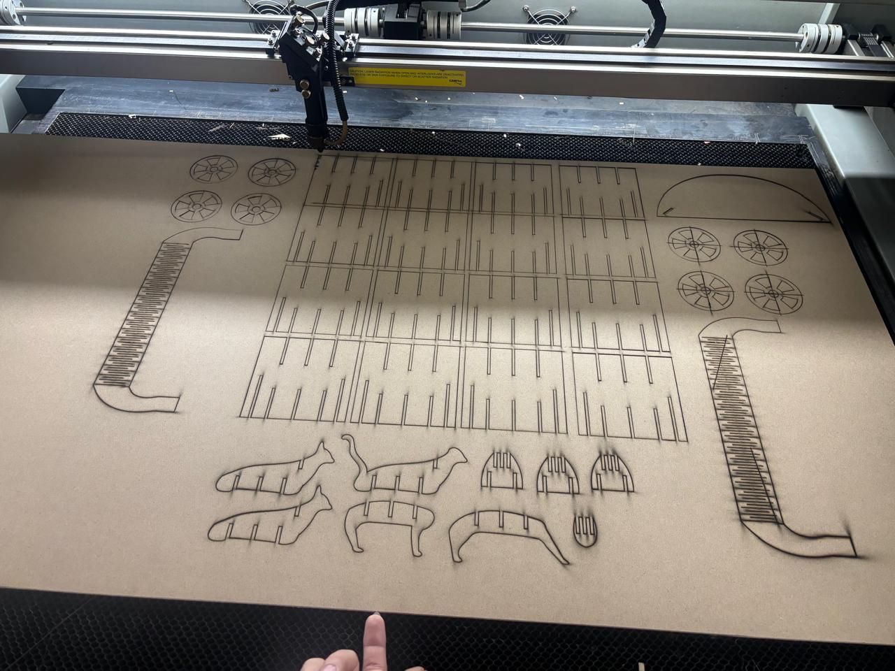
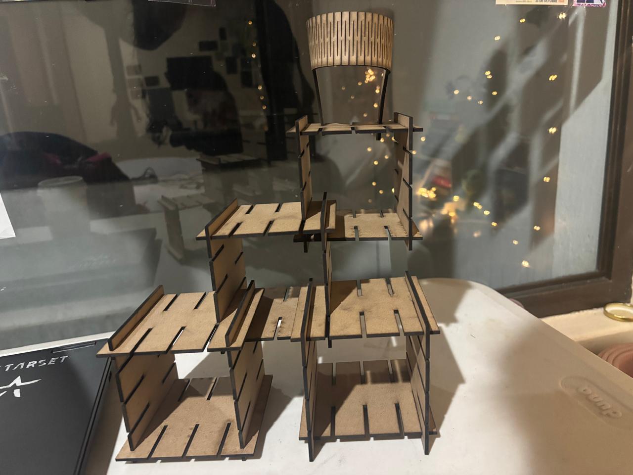
The following pieces were obtained.
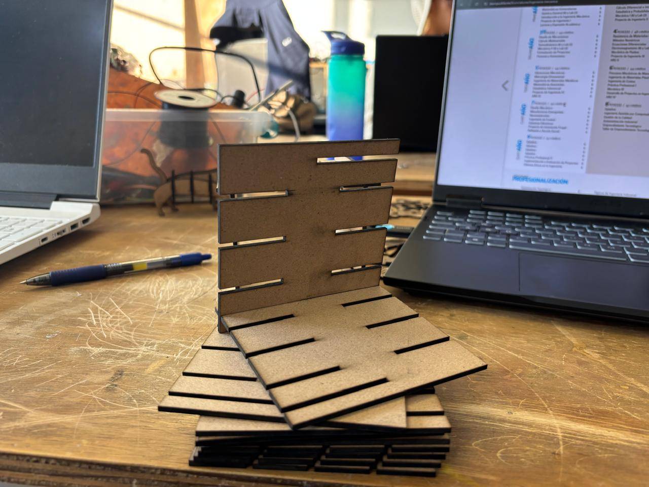
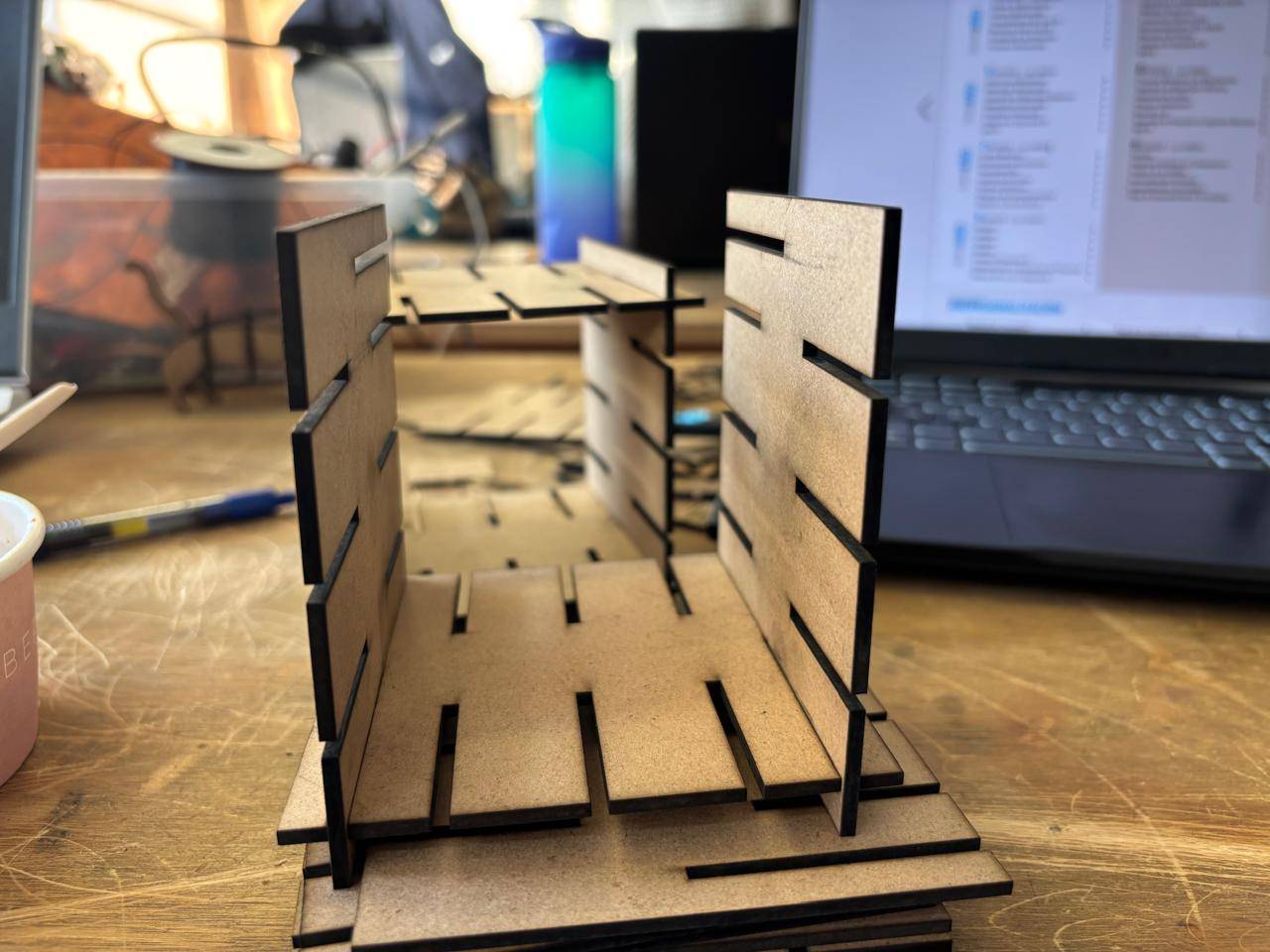
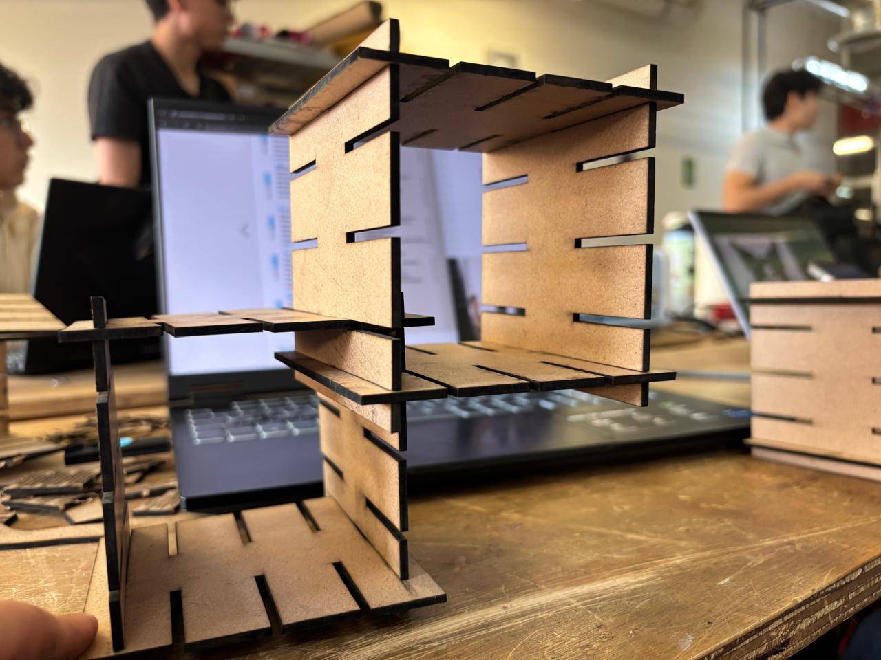
For the shelf assembly, the following result was achieved:
For the cat-shaped assembly, the following result was obtained:
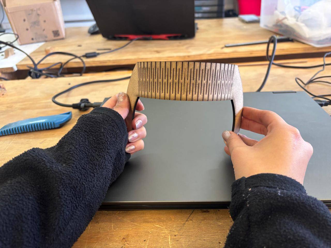
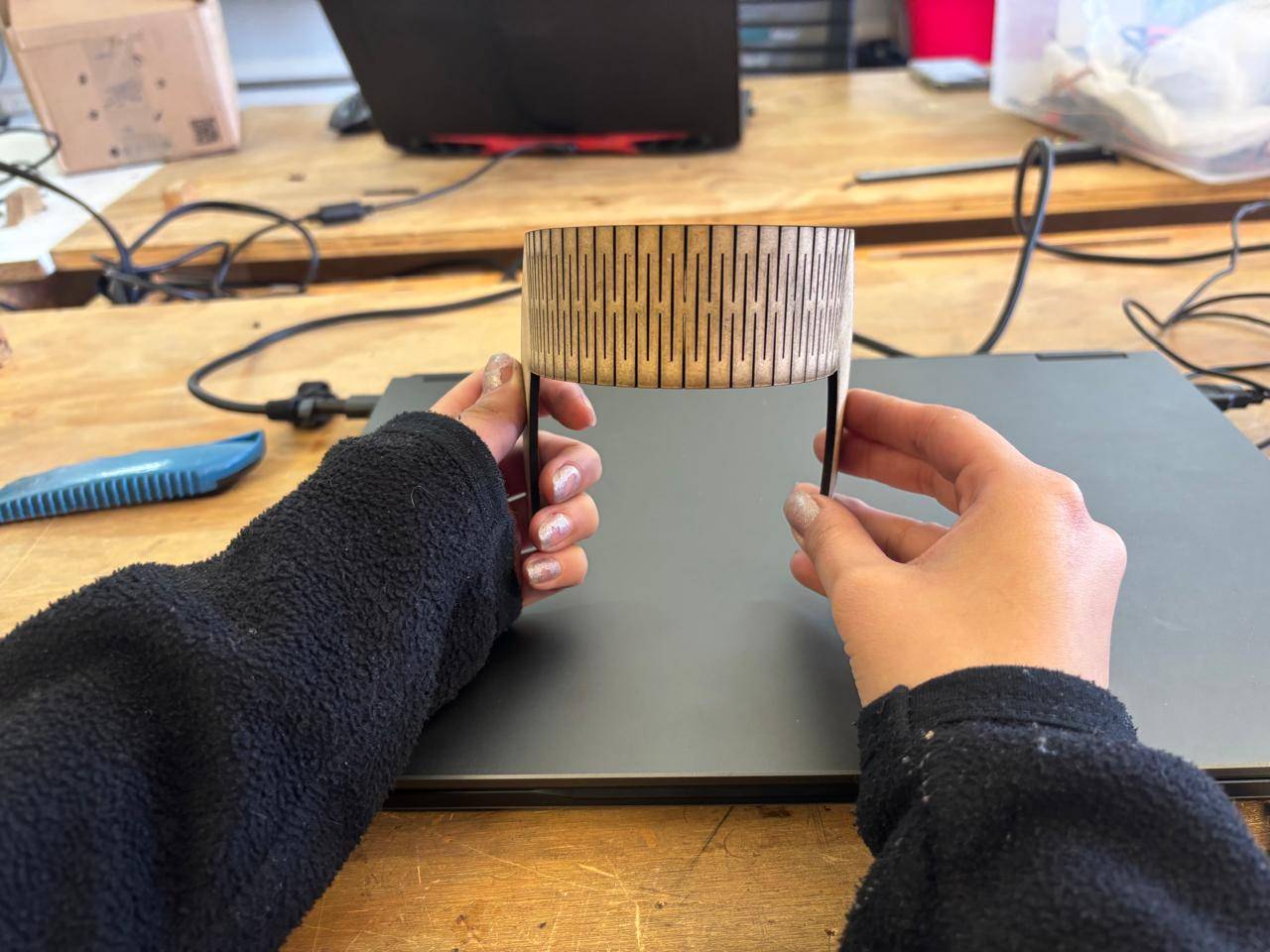
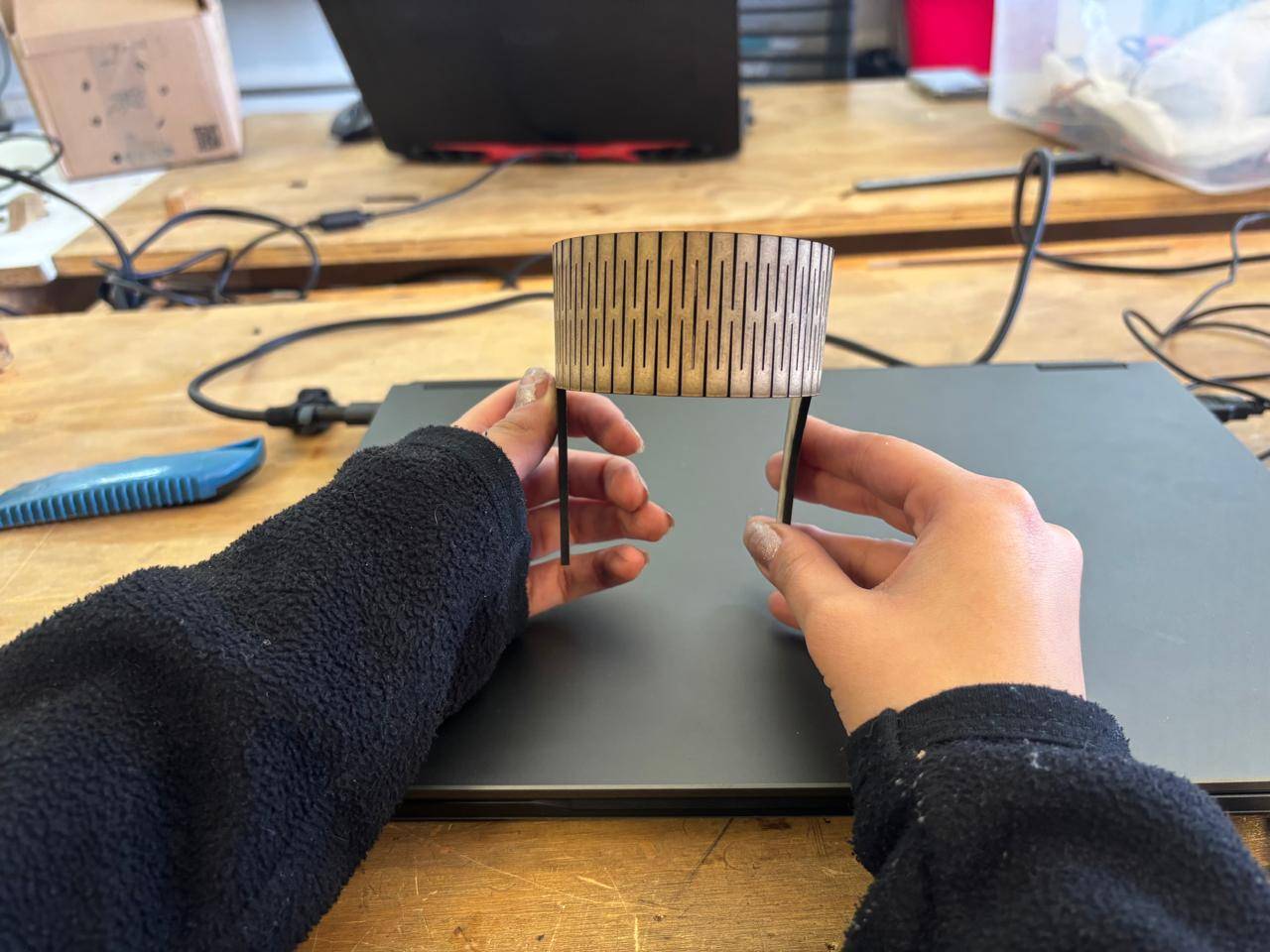
Finally, the assembled living hinge resulted in the following outcome:

Vinyl Cutting
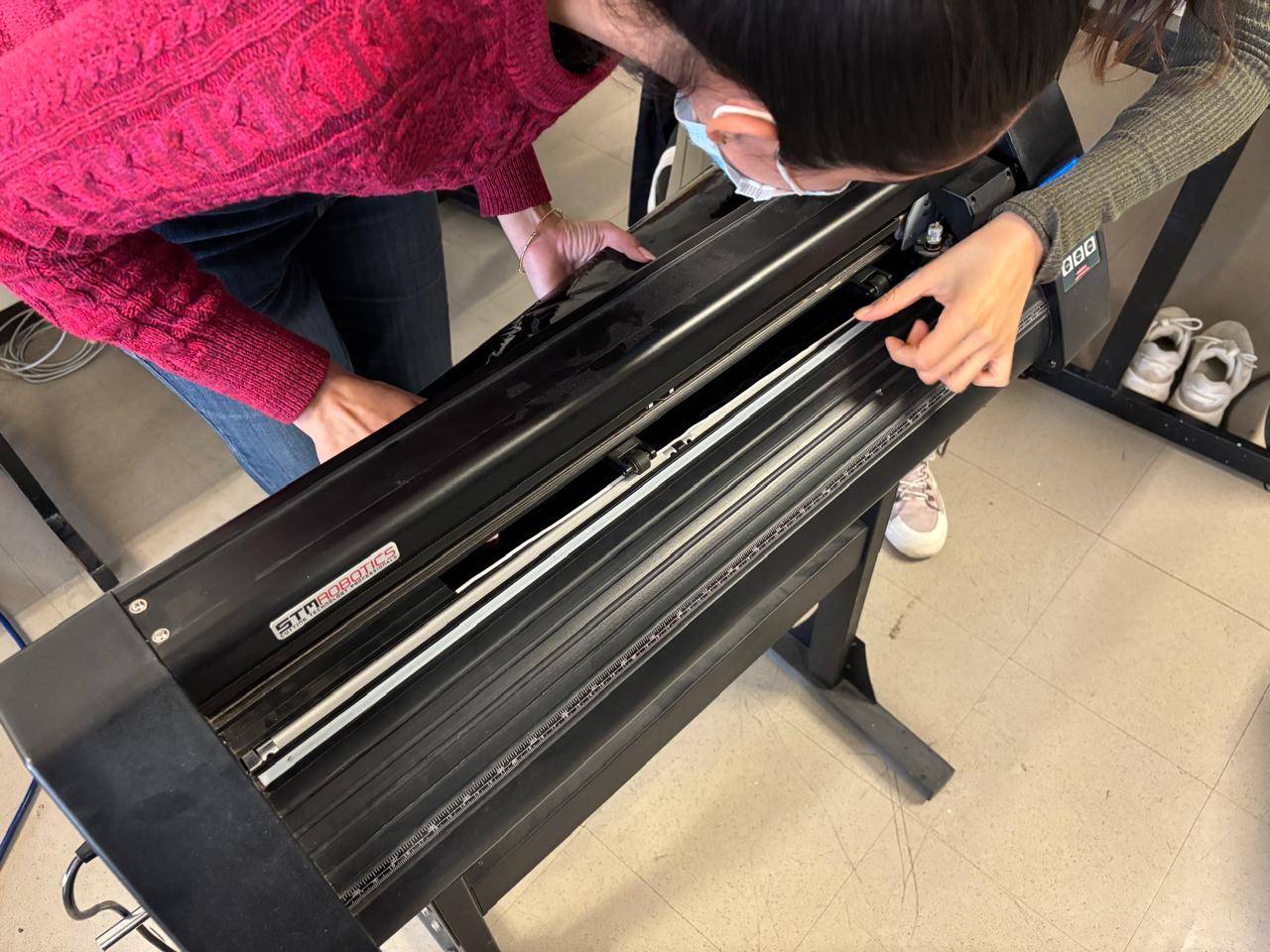
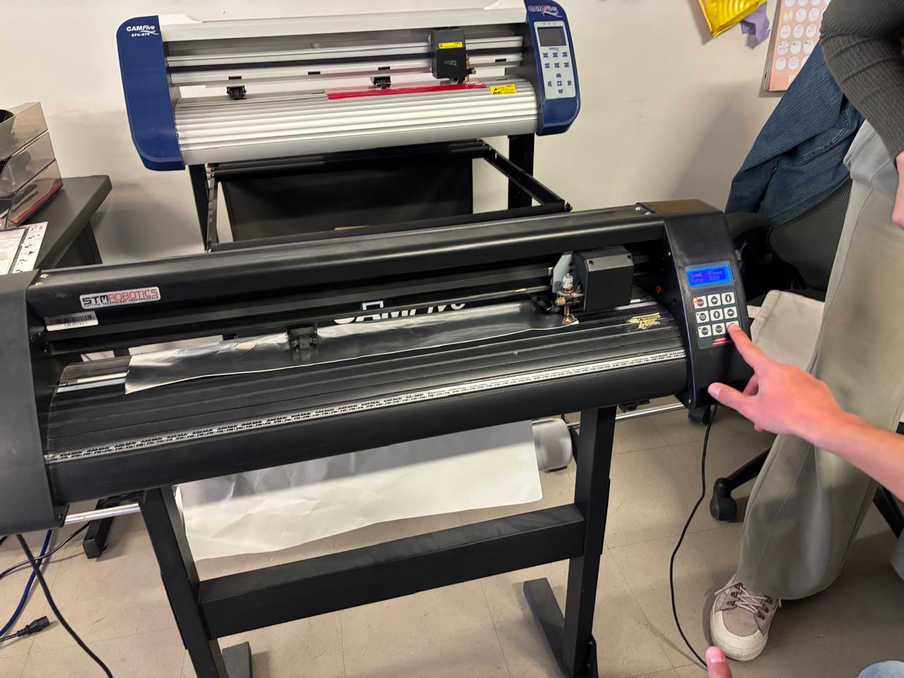
For vinyl cutting, I used the STM Robotics Cutting Plotter, which is designed to cut vinyl, textile, frosted, or reflective materials.
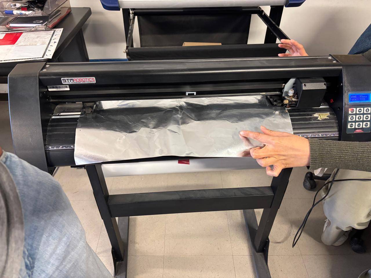
Image Design
To perform cutting, the file must be in .SVG format. In this case, I designed the logo of my favorite band along with characters from anime that I enjoy. The logo was created using Affinity, where the Pen Tool was used to trace the design. The file was then saved in the required format.
Steps to Use the Vinyl Cutter
1.The machine was placed near a power source and a computer containing the driver software. The cutter was connected to the power source, turning it on automatically.
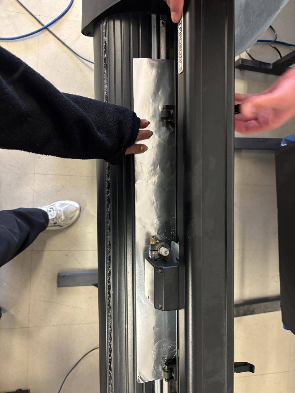
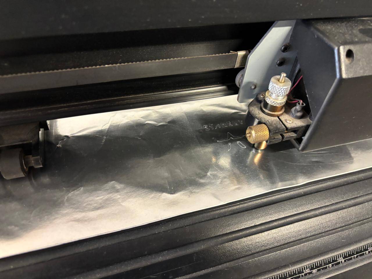
2. Vinyl was used as the main material. The rear clamps were lifted to correctly position the material, and the vinyl was carefully inserted.
Note:
It is important to ensure that the material is not wrinkled, as this may cause tearing or cutting errors.
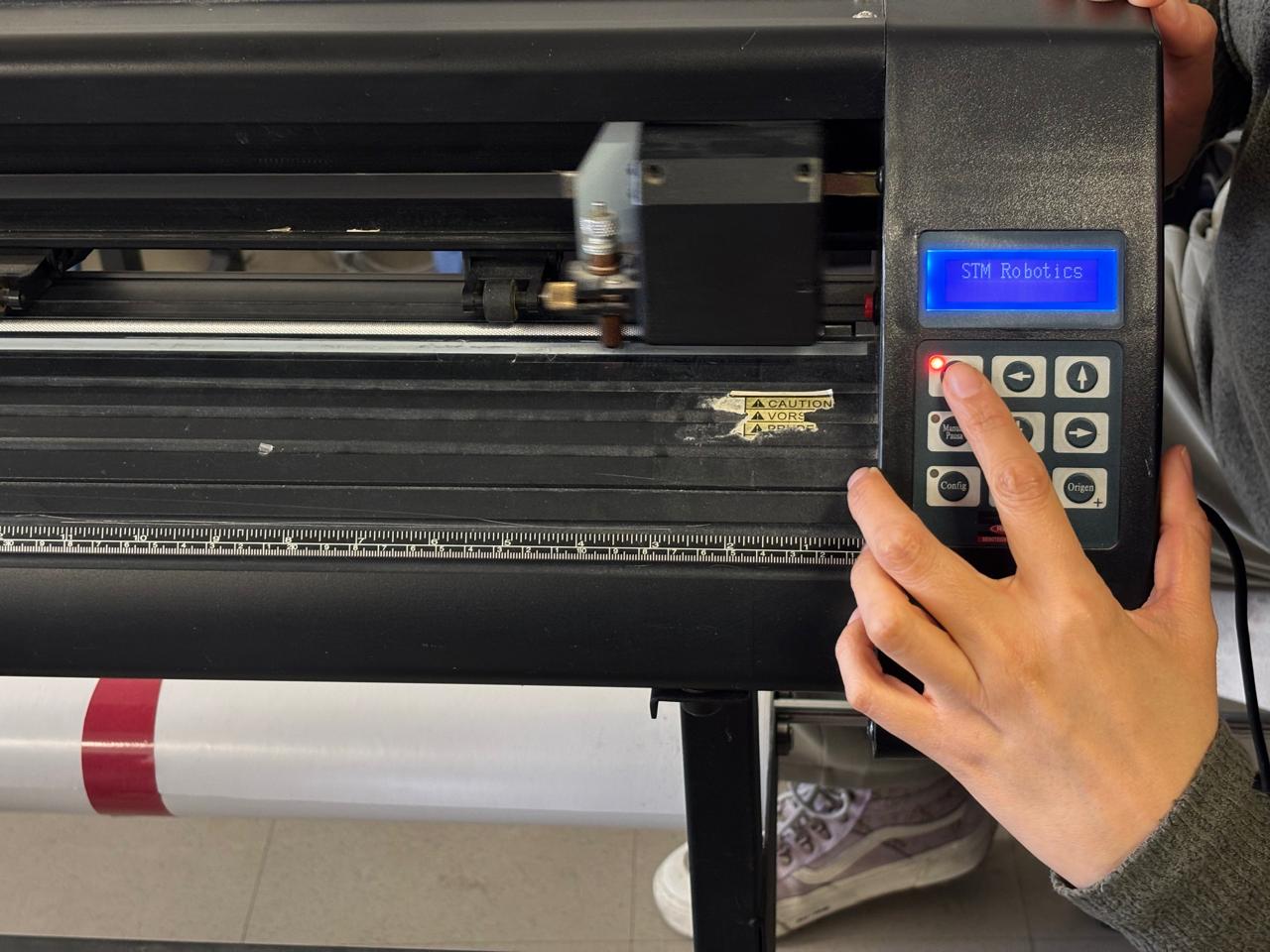
3. Once the vinyl was inserted, the Manual button was pressed. This allowed the origin point to be set. Using the arrow buttons, the cutting head was positioned at the desired location, and the origin button was pressed twice to define the starting point.
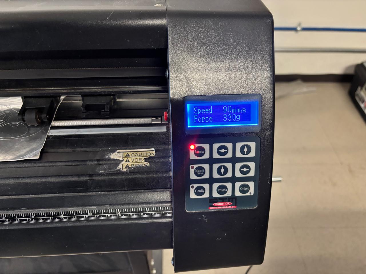
4. To adjust cutting speed and force, the reset button was pressed, and the values were modified using the arrow buttons.
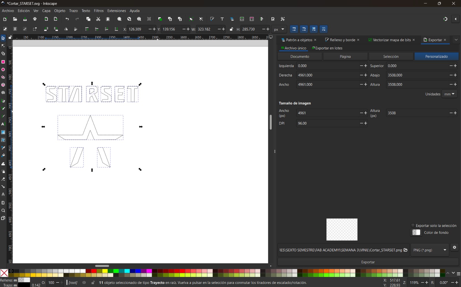
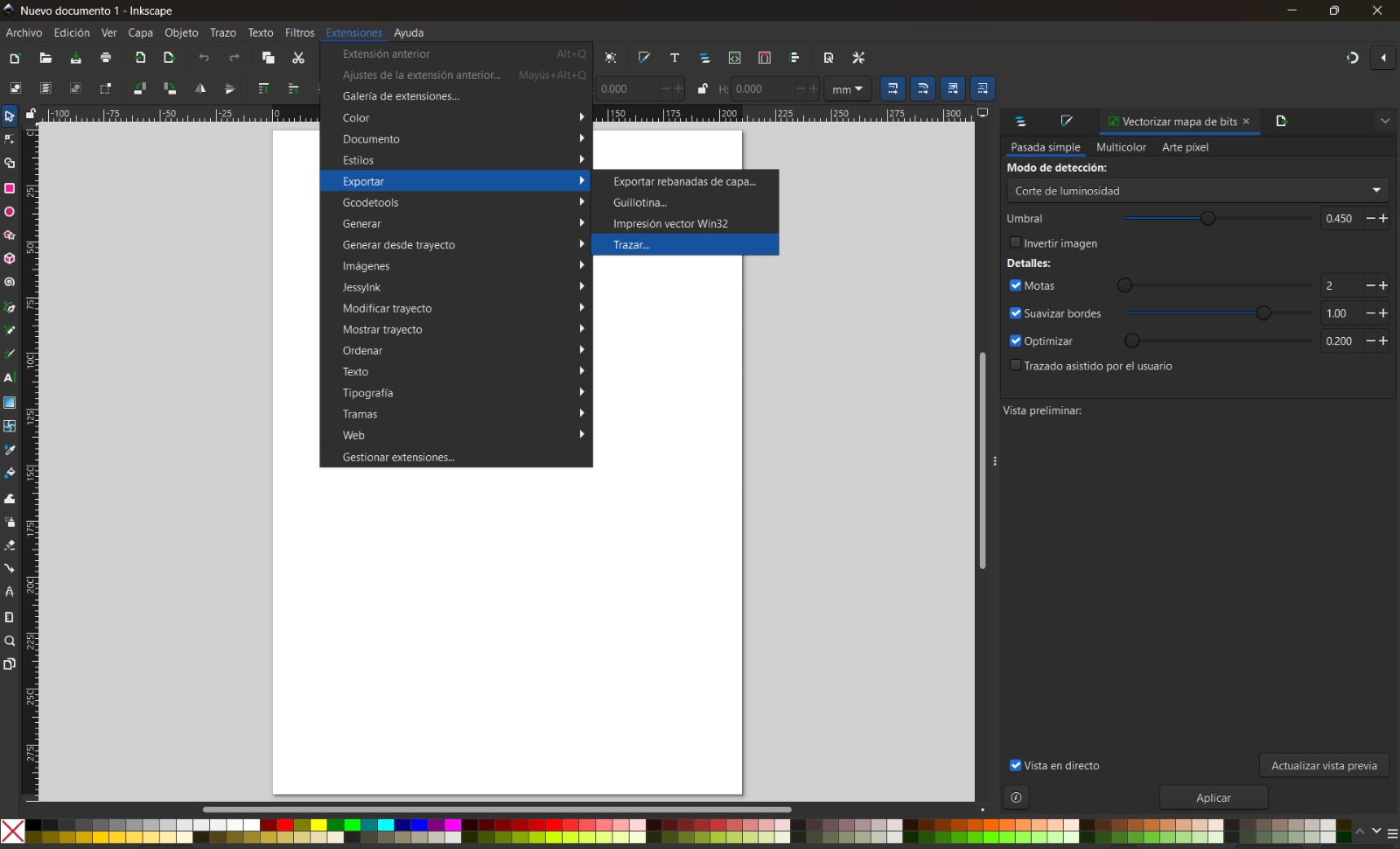
5. In this case, Inkscape was used as the main software to send the vectorized images for cutting. It is important that the files are vectorized, as the installed drivers detect nodes to perform accurate cuts.
6. The vinyl dimensions were measured and assigned to a custom canvas. The .SVG file was then opened, and the cut size was adjusted. This can be accessed by pressing Ctrl + Shift + D.

7. The following menu was selected: Extensions → Export → Plot. A window opened automatically, allowing adjustment of plotting parameters and paper size.
8. For the cutting parameters, speed and pressure I used for speed 90mm/s, and for force 330g.
9. Finally, the process was confirmed to start the cut.
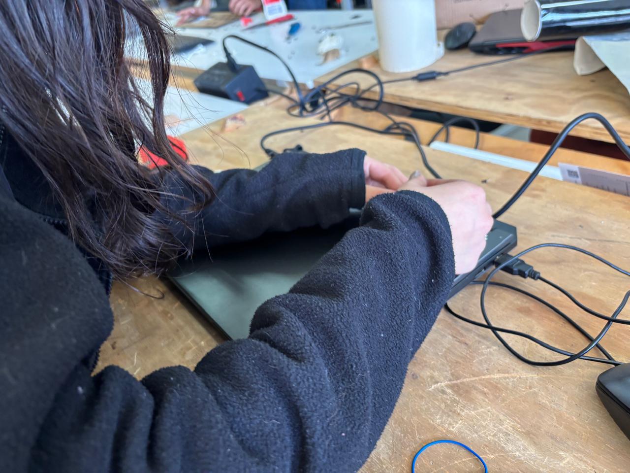
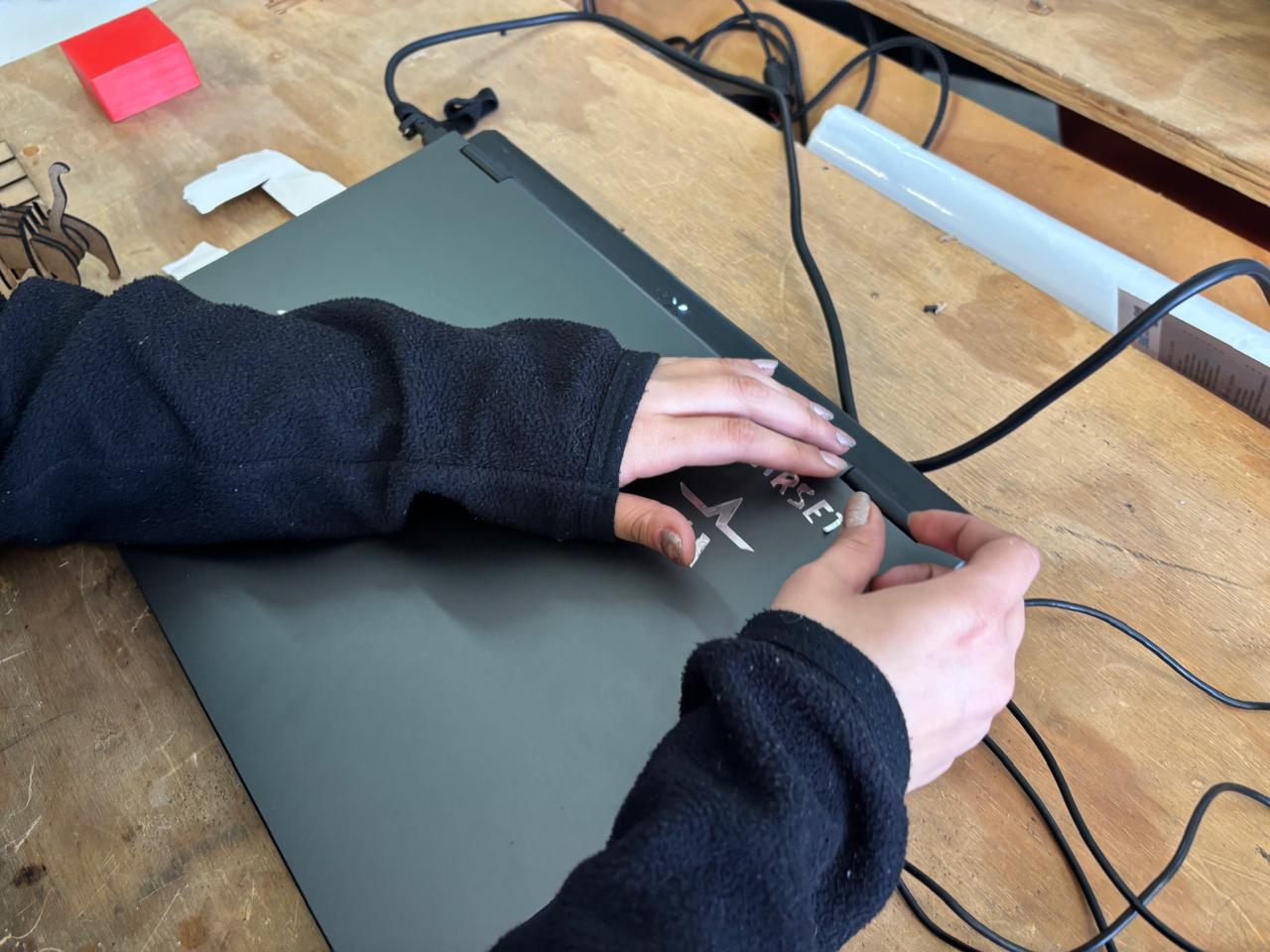
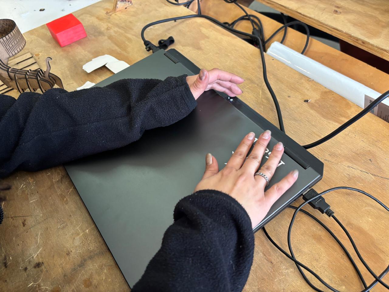
10. Once cutting was completed, the vinyl was removed, the excess material was peeled away, and the design was applied to my computer.
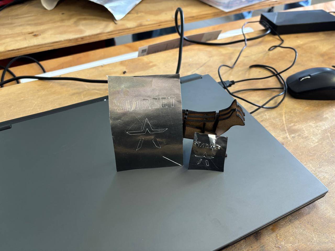
11. This is how it looks like the process of the peeling, and transfering.
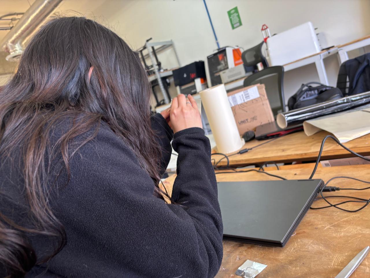
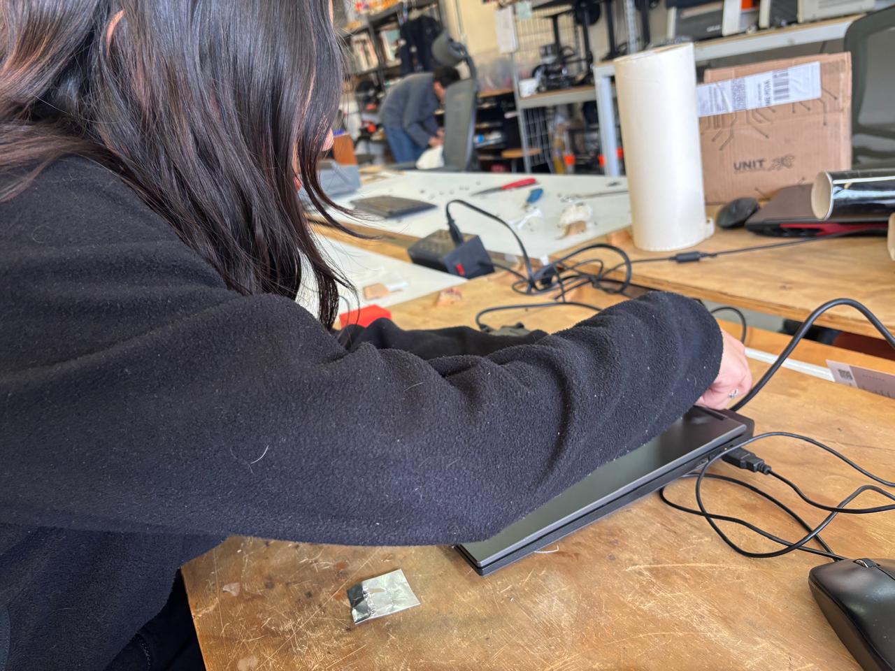
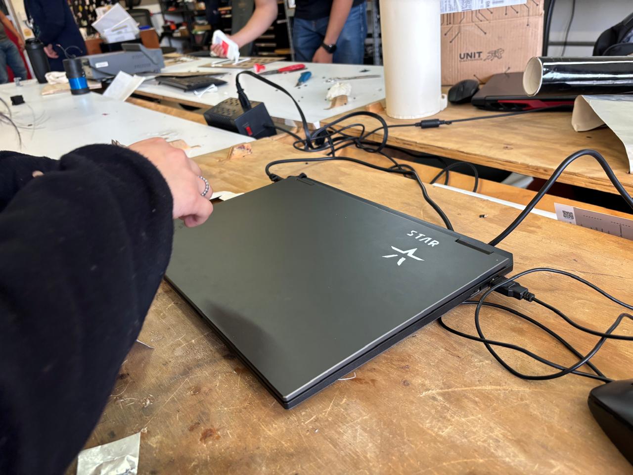
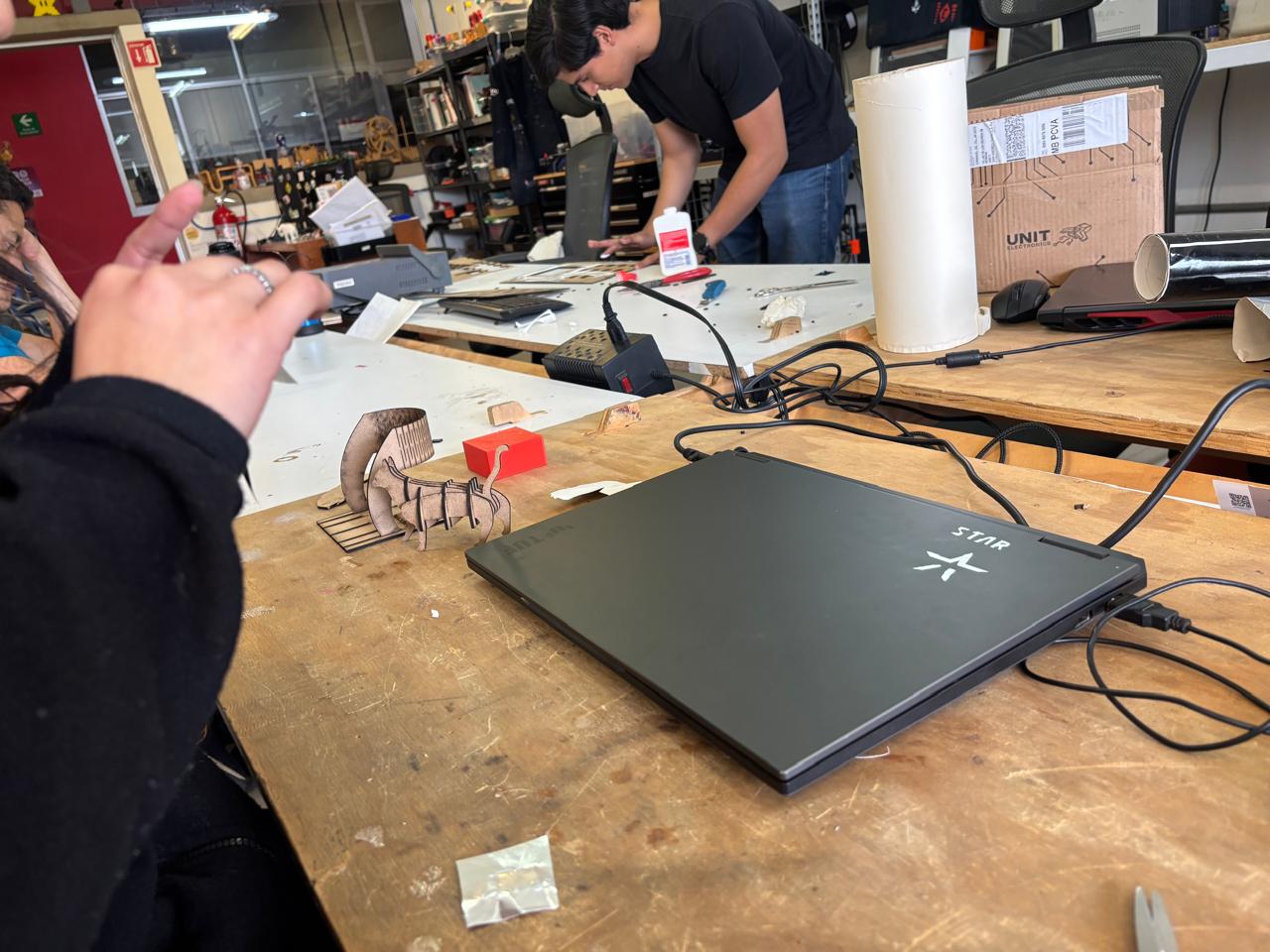
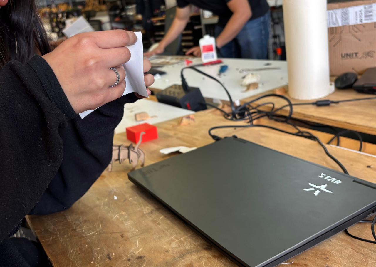
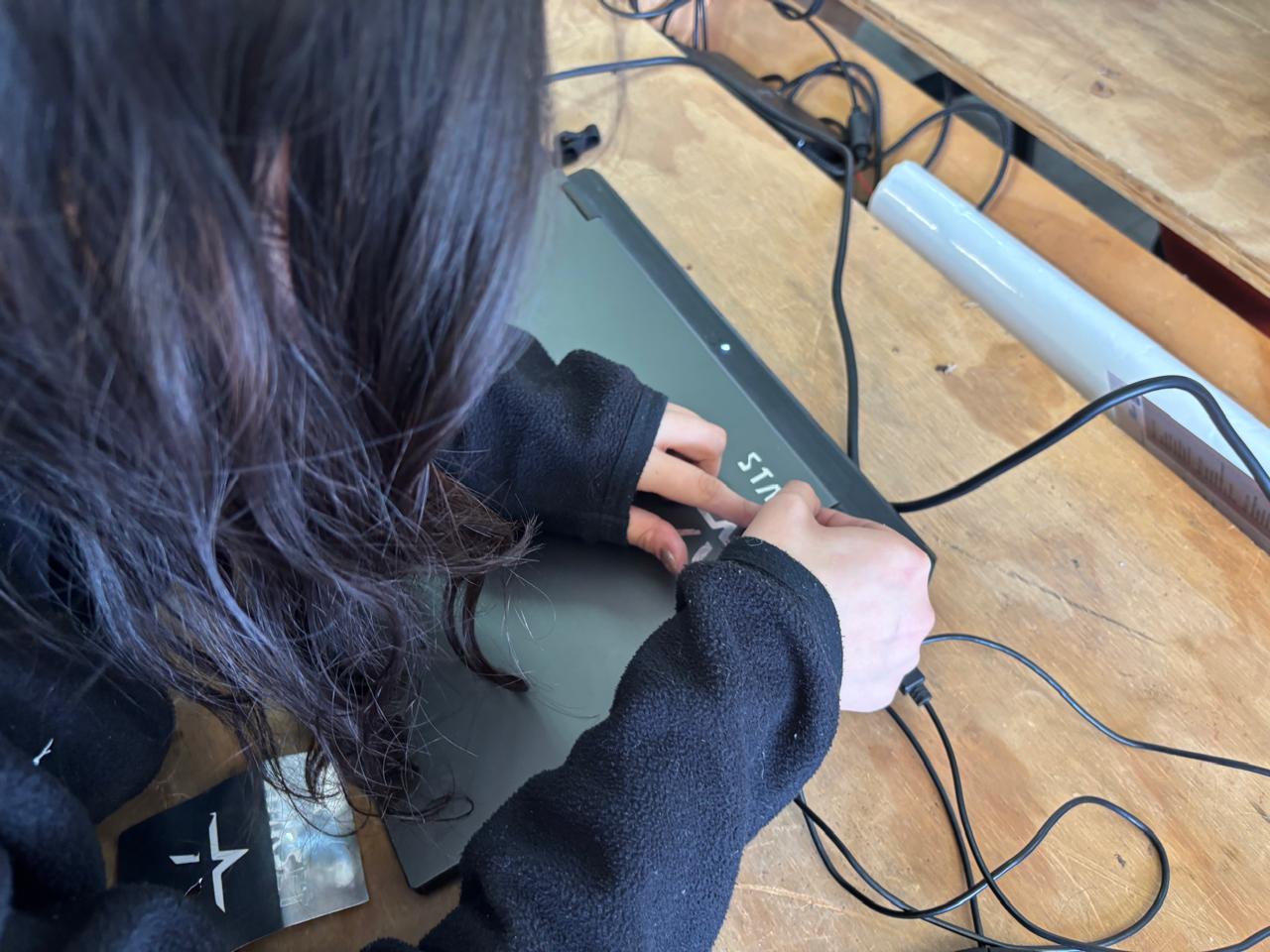
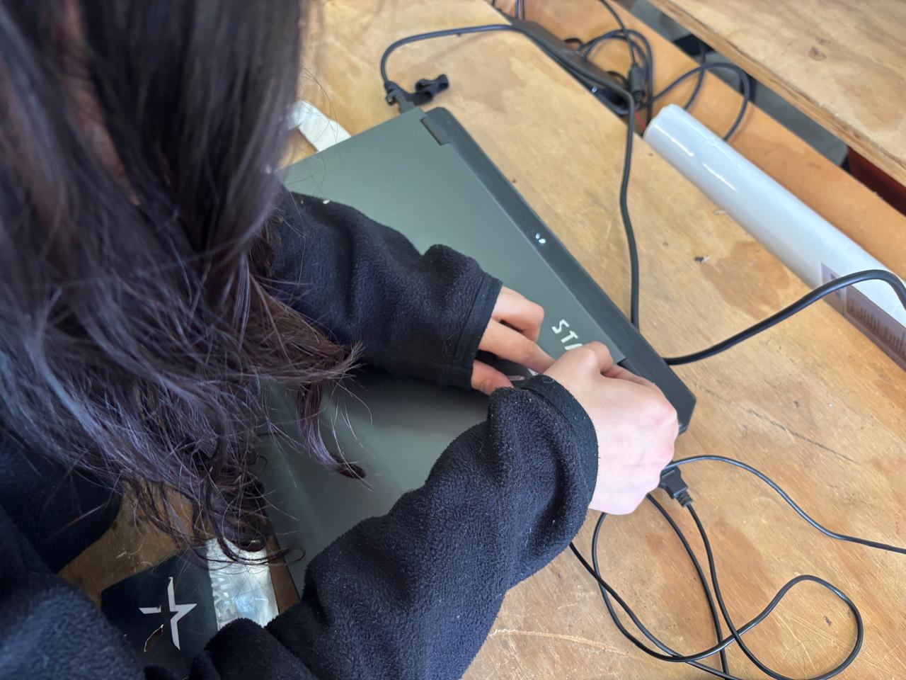
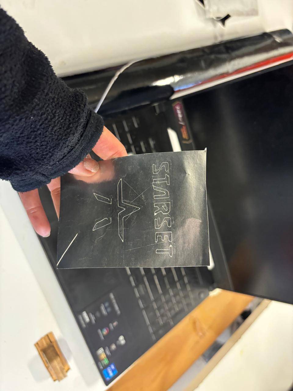
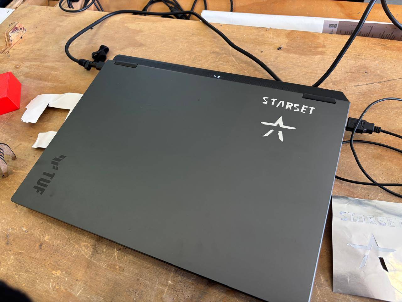
12. Finally, this is how it looks like:
If you want to access to my work from this week, please click here to download!
Finally, for the group assignment for this week, you can find the information here