Week 13 - Molding and Casting
This week's assignment focused on molding and casting. We had to design a mold based on a specific process, create it with a smooth surface finish that did not reveal the production toolpath, and use it to cast parts. For our group assignment , we reviewed the safety data sheets for each of the molding and casting materials. Then, we used these materials to create and compare test casts. Additionally, we compared printed molds with milled molds.
Work log
Completed tasks
- Designed appropriate objects within the limitations of my chosen process.
- Demonstrate workflows used in mold design, construction and casting.
1.What is molding and casting?
Molding and casting are two manufacturing processes used together to create objects by shaping a material into a desired form. Molding involves creating a hollow form, known as the mold, which defines the shape of the final object. This mold serves as a negative of the part intended for production. Casting is the process of filling that mold with a liquid or semi-liquid material, allowing it to solidify before removing the finished part.
- Pattern creation: The pattern is the original object whose shape is to be reproduced; it serves as the reference from which the mold is made. The pattern can be constructed from various materials, including 3D printed parts (such as PLA or resin), machined wood, foam, plastic, sculpted clay, wax, or even an existing object.
- Mold fabrication: The mold serves as the hollow form that shapes the cast material into the intended object. The mold fabrication process begins with constructing a containment wall around the pattern. Once the mold box is built, the mold material (consisting of part A and part B) is mixed in accordance with the manufacturer's specified ratio, typically measured by weight.
- Casting material pour: This step involves filling the completed mold with the actual material for the part. Most resins consist of a two-part system (resin + hardener) that requires precise mixing ratios. During the mixing and pouring process, bubbles may form, so it is recommended to place the filled mold under pressure while it cures. This is typically achieved using a vacuum chamber.
- Solidification: This is the waiting phase during which the cast material transitions from liquid to solid. Temperature is a key factor; higher ambient temperatures generally accelerate curing, while colder conditions slow it down. Pot life refers to the working time after mixing before the material begins to gel. Many resins can be demolded within 30 to 60 minutes, but they do not achieve full mechanical strength for 24 hours.
- Demolding: This process involves removing the solidified part from the mold. To determine if the curing is complete, press on the part; it should feel firm and not tacky. For rigid molds, gently flex or tap the mold. When using silicone molds, carefully peel the mold back, starting from the edges and working inward. The flexibility of silicone allows it to release from undercuts that could damage a rigid mold. In the case of two-part molds, separate the halves before extracting the part.
2. What object did I decide to mold? A Fin-Ray spoke!
A Fin Ray spoke is a flexible triangular or ribbed structure that bends in the direction of the applied force. In the field of soft robotics, Fin Ray spokes can deform around objects due to their internal ribs and crossbeams, which bend when subjected to contact forces. I have been working with Fin Ray spokes for some time, primarily 3D printing them using TPU 95HF. However, my instructor suggested that I try creating a Fin Ray spoke using silicone to compare its performance with the 3D printed versions.
3. Mold design and fabrication
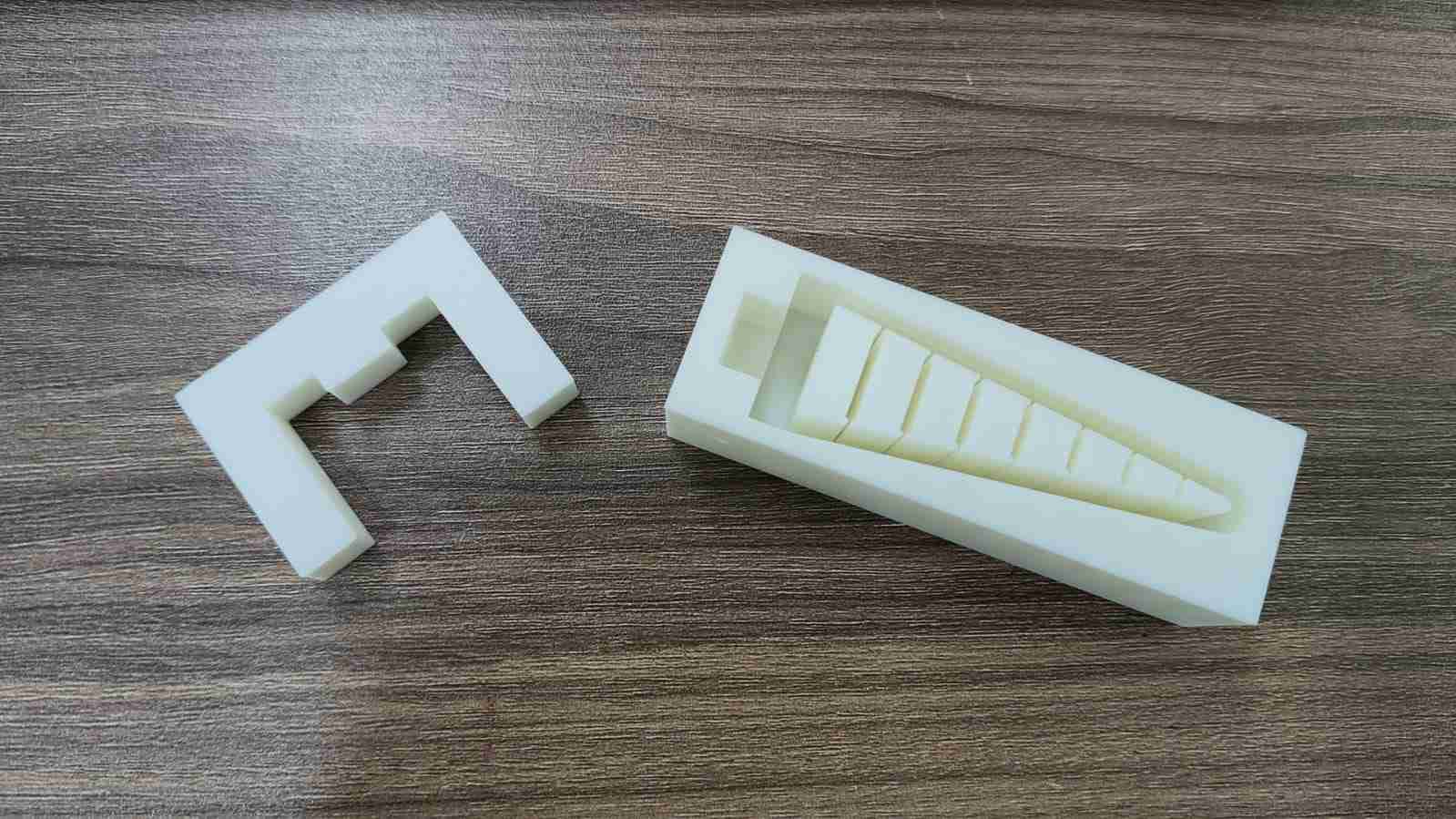
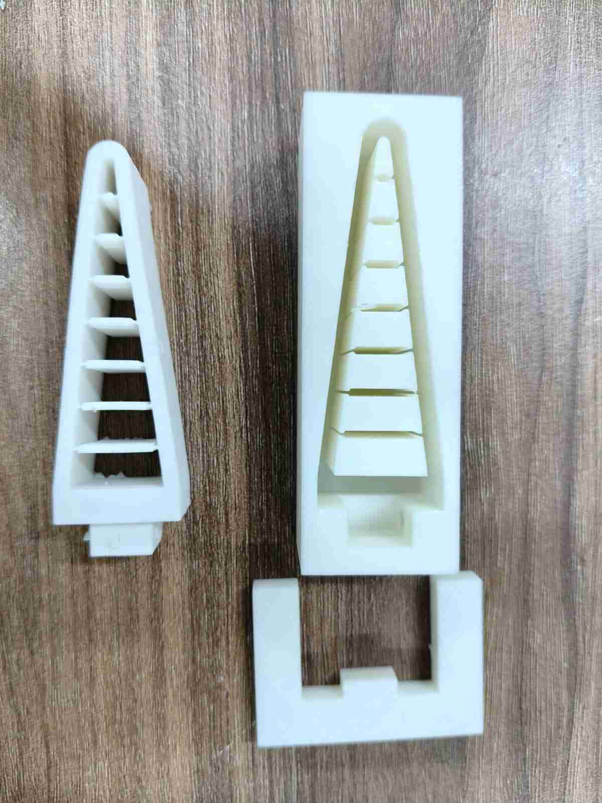
As a first step, I evaluated the Fin Ray spoke appendage currently used in my robot. From the beginning, I identified the mounting hole as the trickiest part to mold. I initially considered molding the Fin Ray without its mounting hole, but then I realized I could design a two-part mold. After deciding on silicone resin as my casting material, I designed my mold to be 3D-printable.

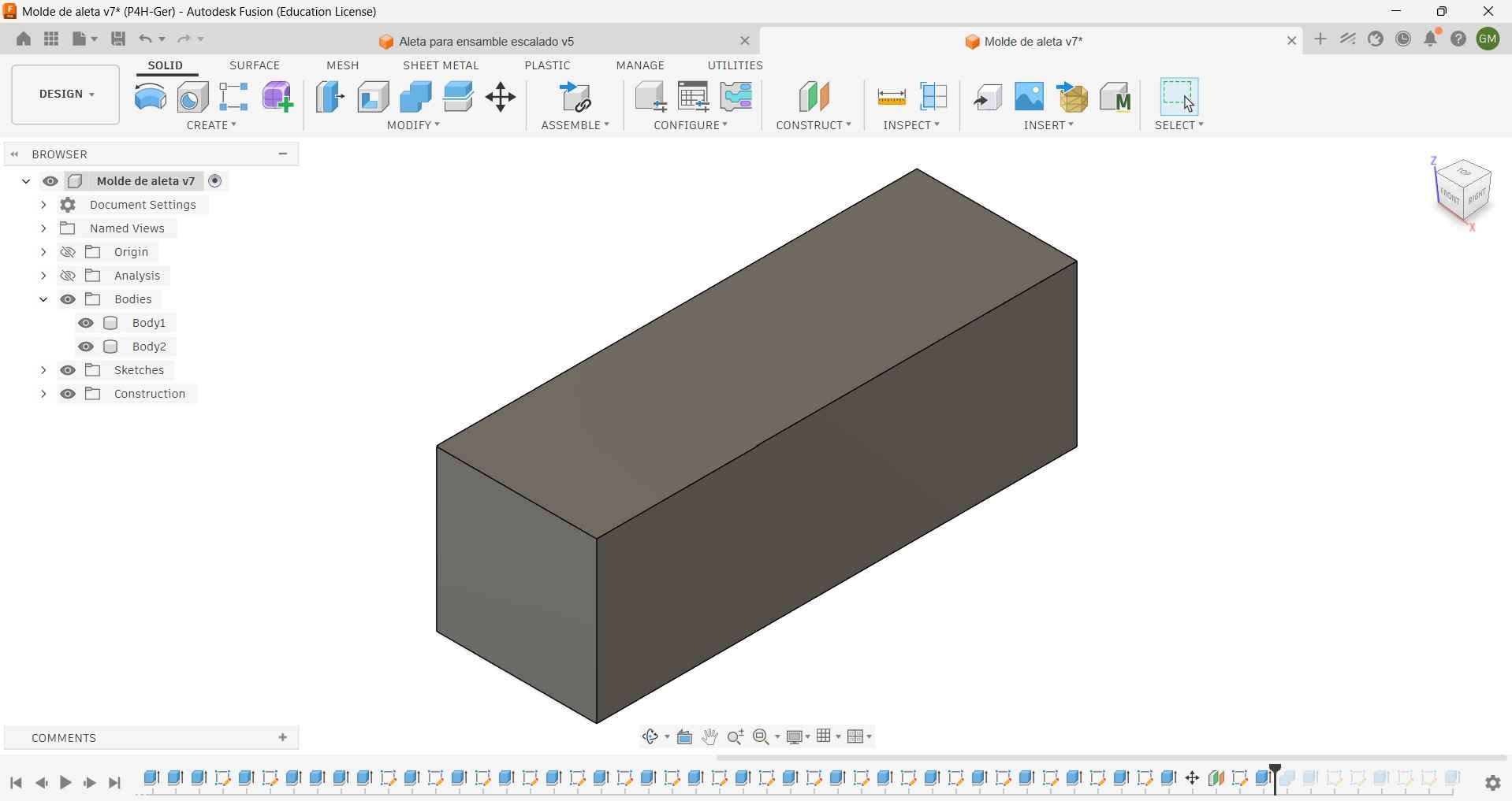
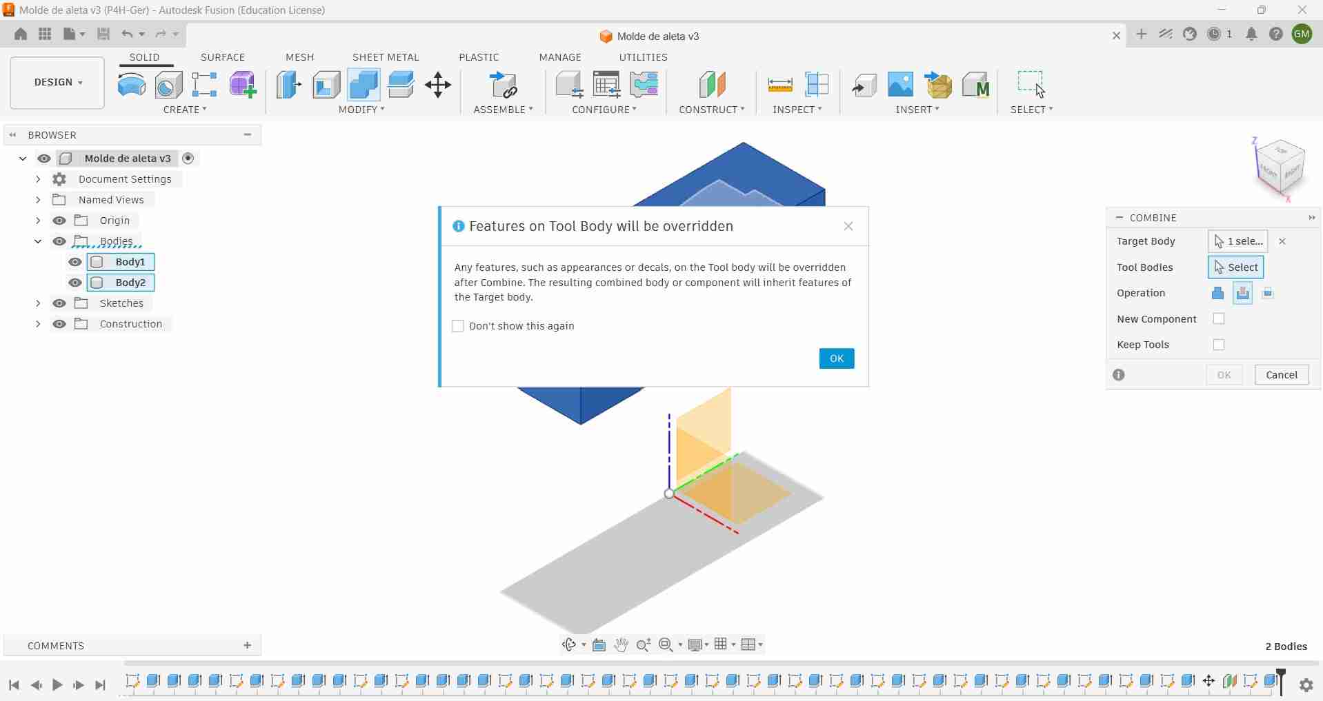
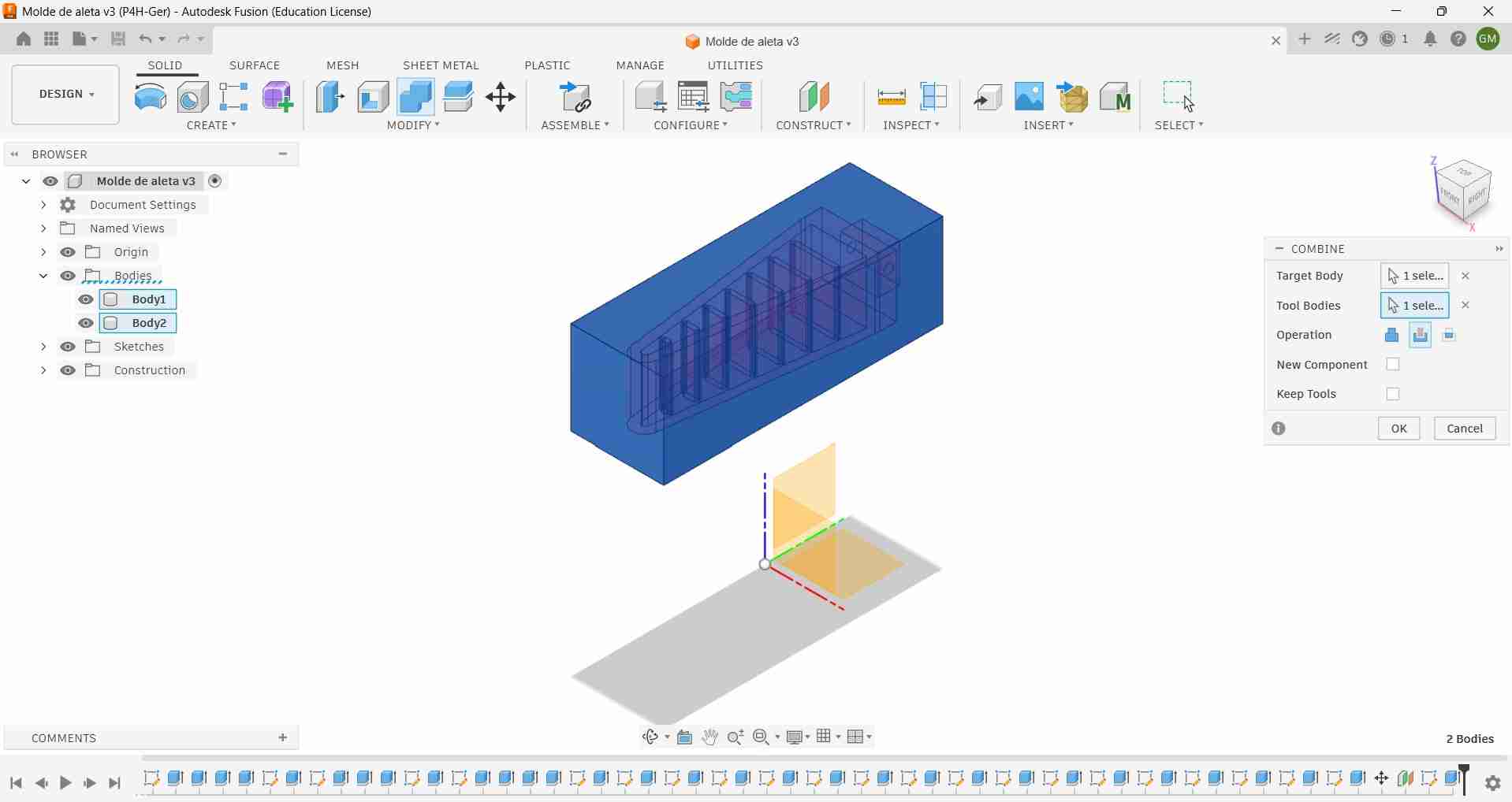
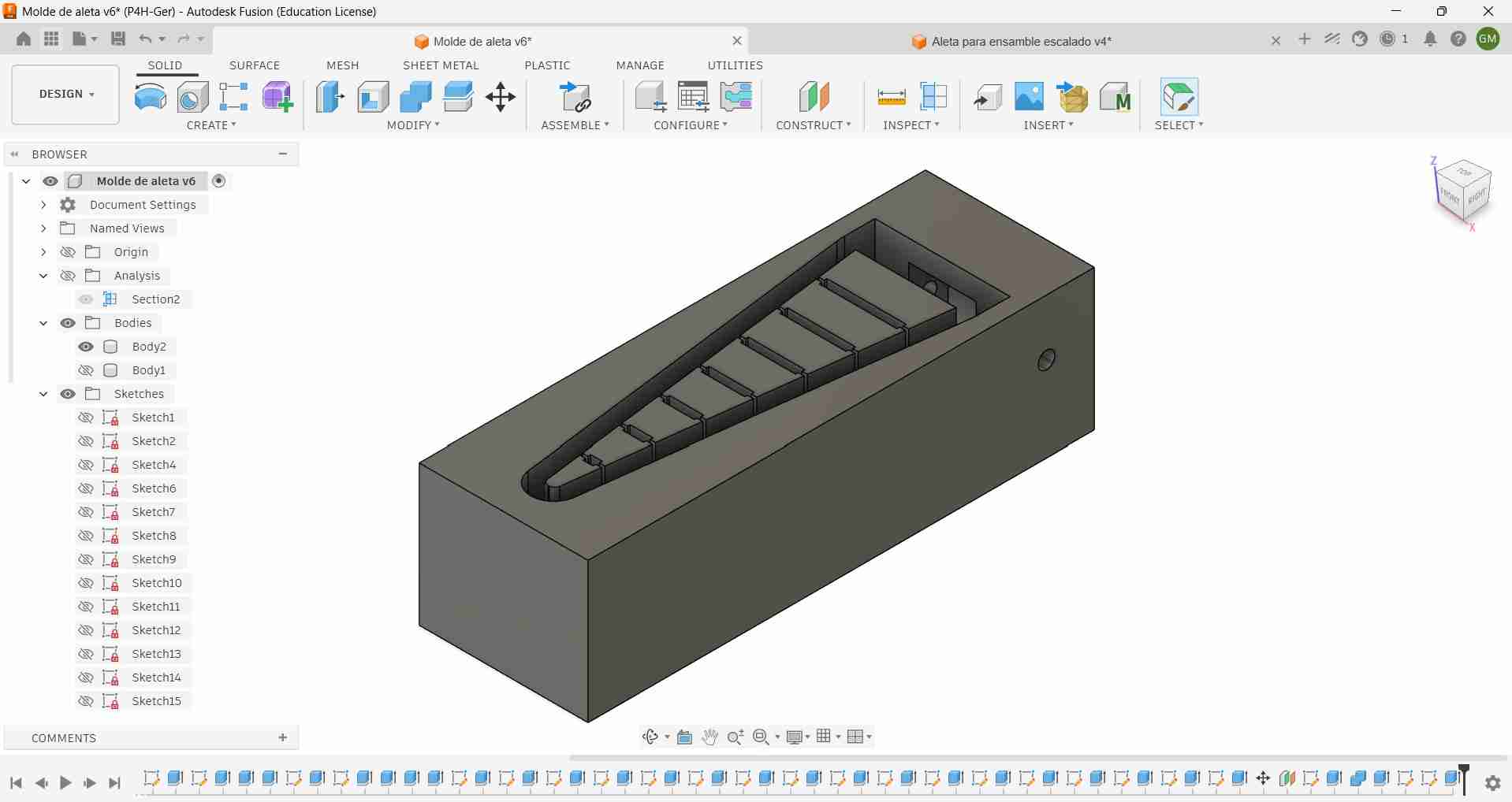
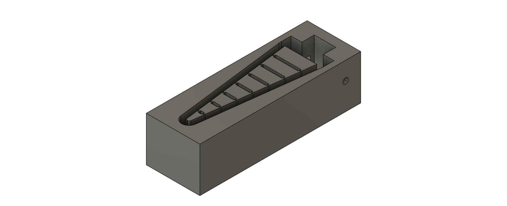
I designed this mold using Fusion 360. This mold could also be replicated in other CAD software using a similar workflow, although the names of operations and options may vary. I began by enclosing my Fin Ray in a rectangular box. Then, I used the subtract option under the Combine operation, with the Fin Ray as the tool and the box as the target. This process created a hollow section inside the box that matches the shape of the Fin Ray.
After hollowing out the box, I applied a negative extrusion operation until the Fin-Ray shape became visible. Next, I performed a circular extrusion in the section designated for the mounting hole, which will attach the Fin Ray to the wheel-leg spokes of my robot. This hole will also serve as the mounting point for the other part of my mold using an M3 screw.
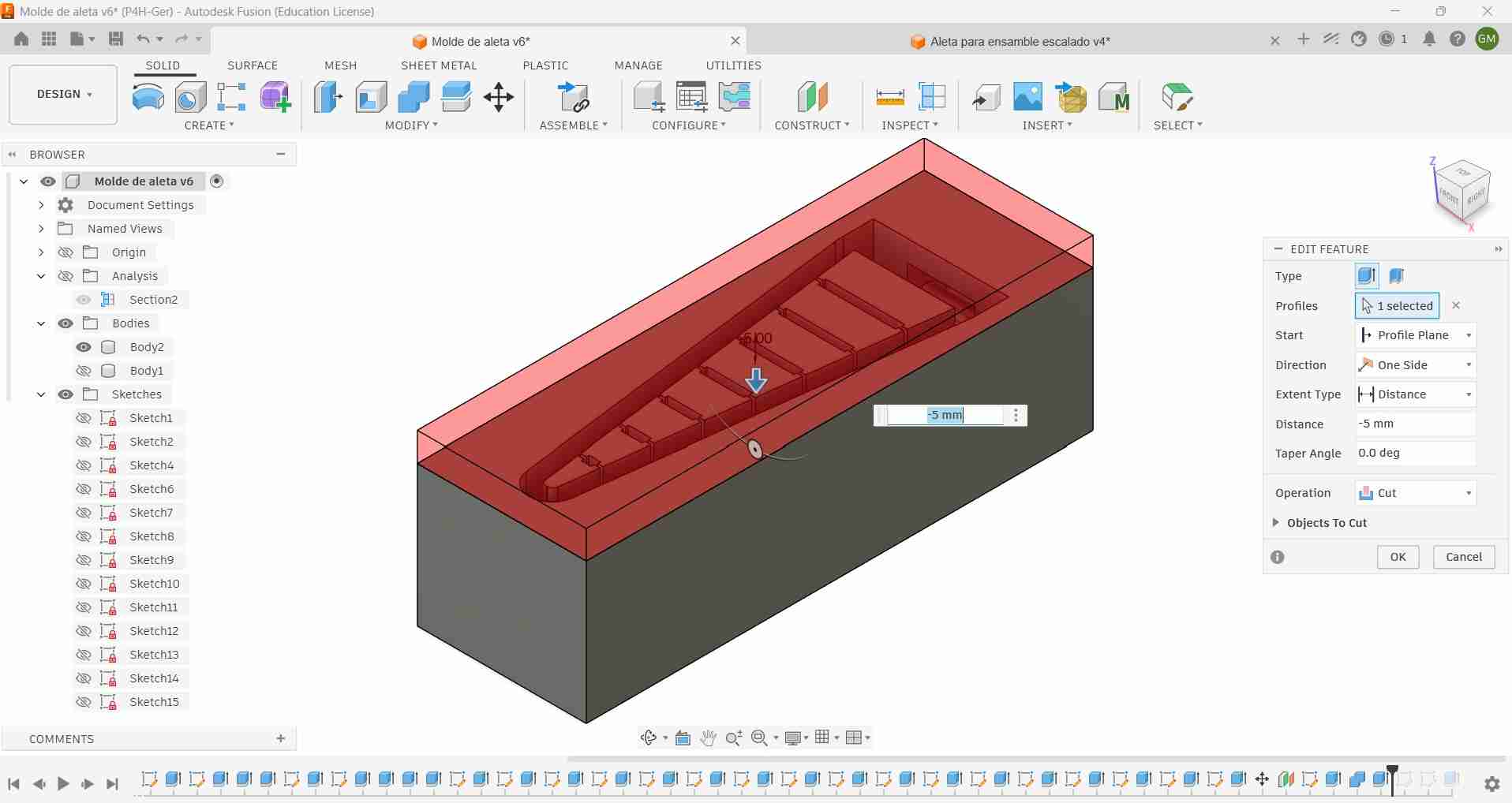
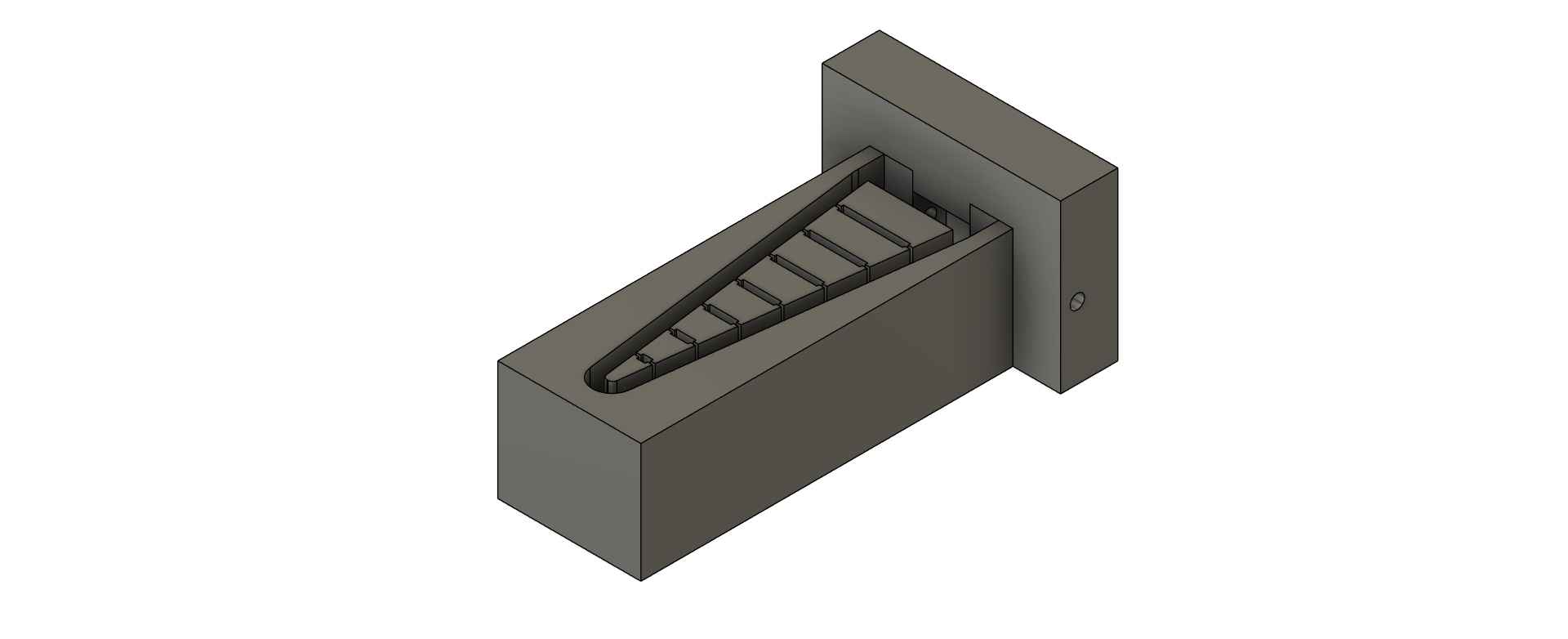
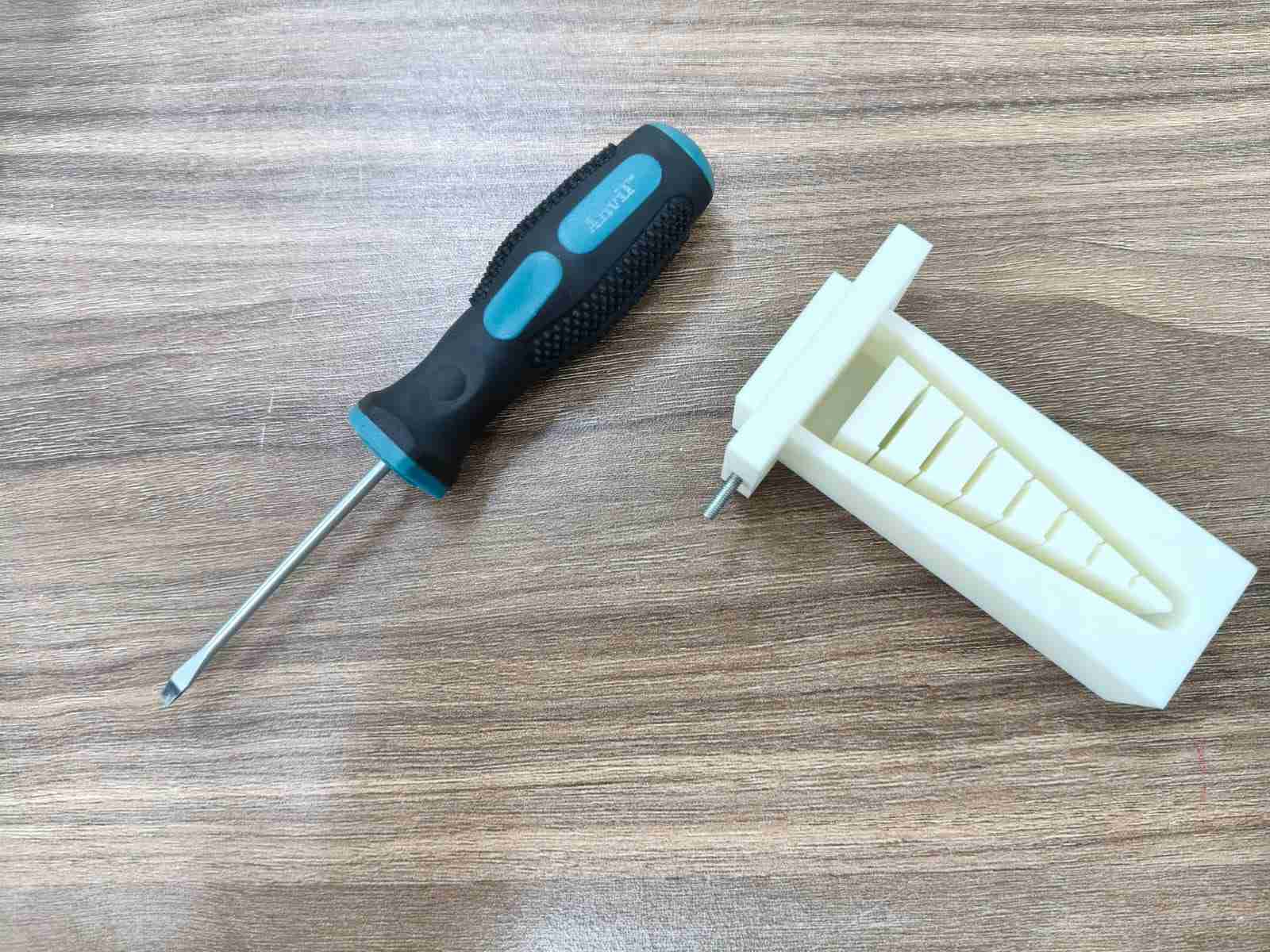
Lastly, I applied a negative extrusion to the mounting hole section. This extrusion was necessary for the removal of the molded part after solidification. The shape of the mounting hole section would then be formed by the removing holder of the mold.
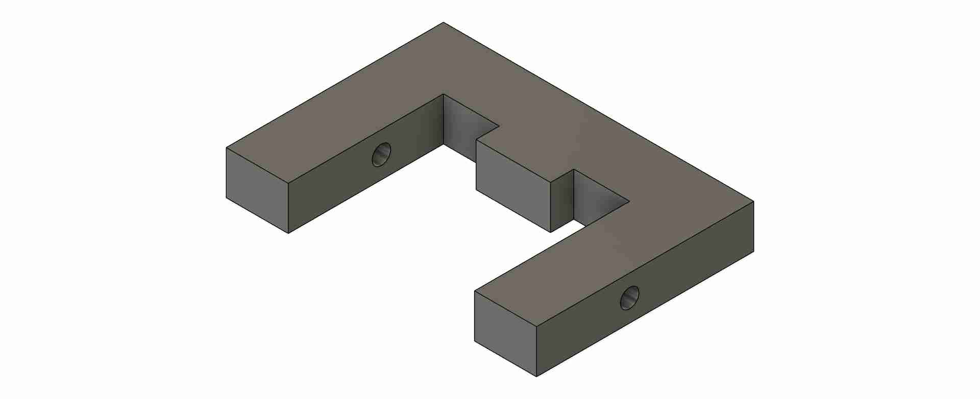
The design of the removing holder includes an M3 hole for creating the mounting hole, along with an extruded surface for the mounting hole section.
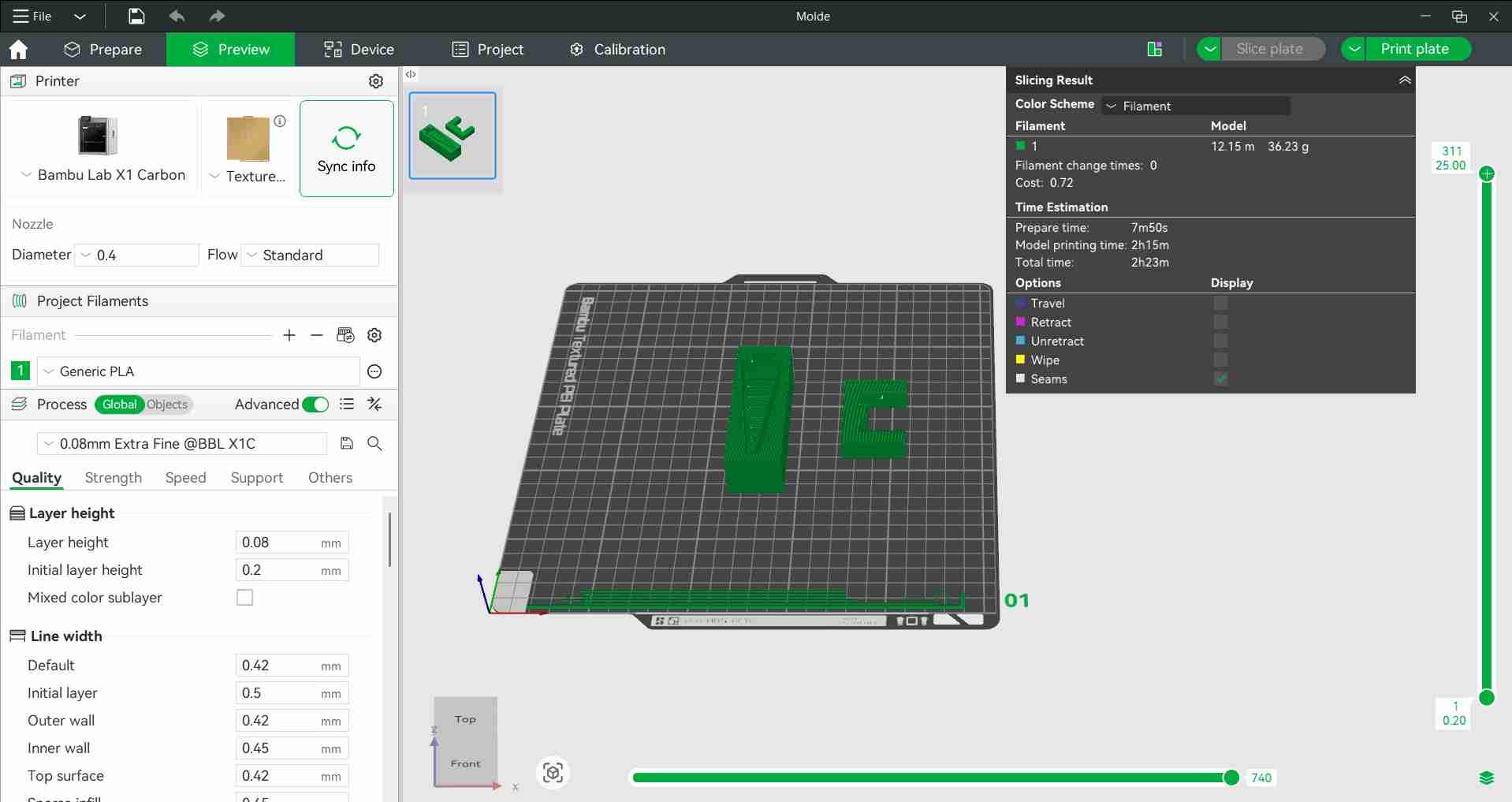
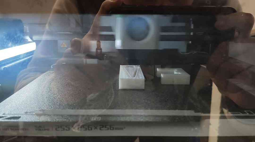
As outlined in the assignment requirements, our molded parts were not required to display the toolpaths necessary for manufacturing. Consequently, I chose to 3D print my mold using an X1C Bambulab printer with a 0.008mm layer height. The printing process took approximately two hours, which surprised me. Nevertheless, I was pleased with the smooth surface that this layer setting produced.
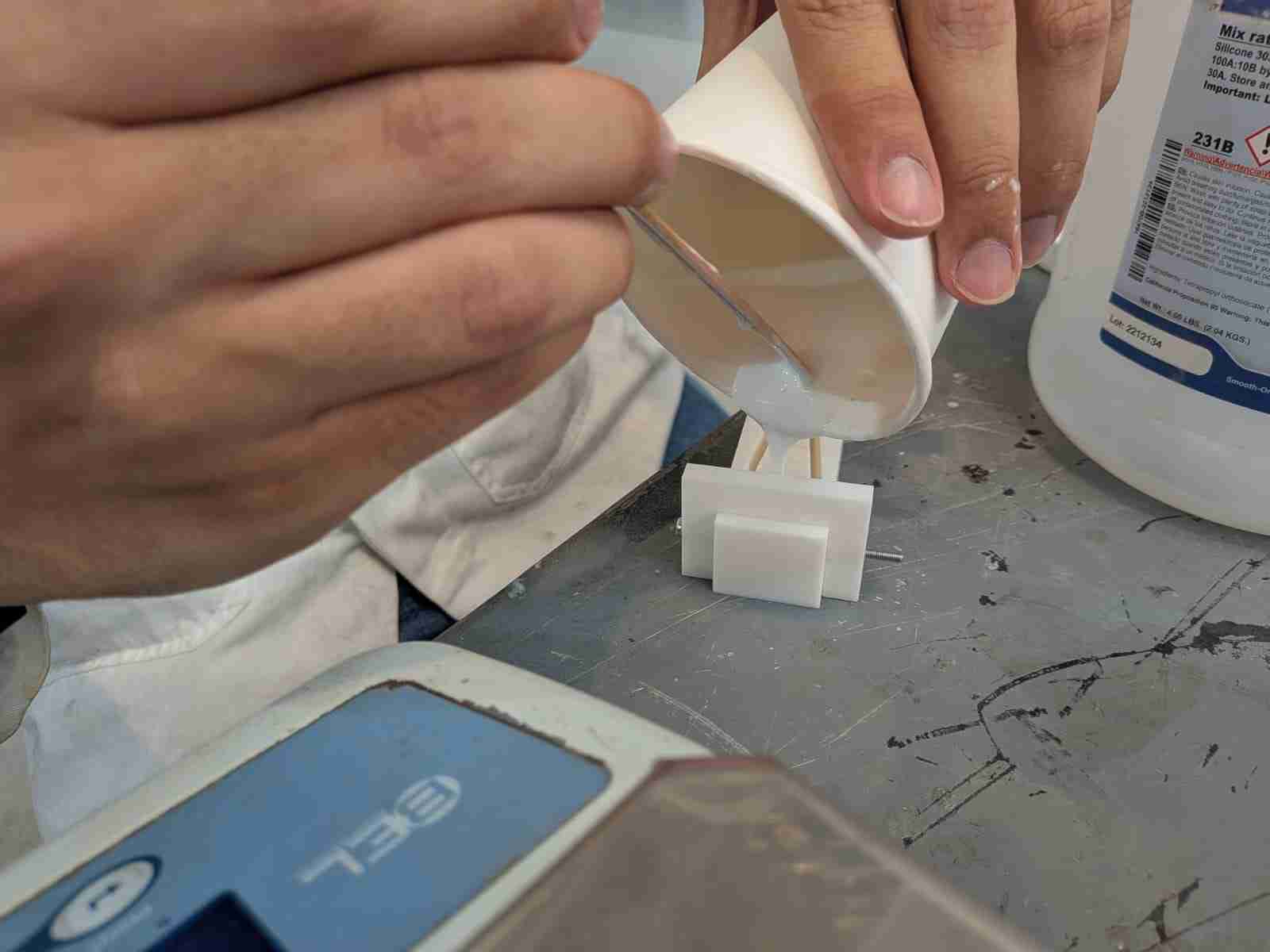
4. Casting Material Pour
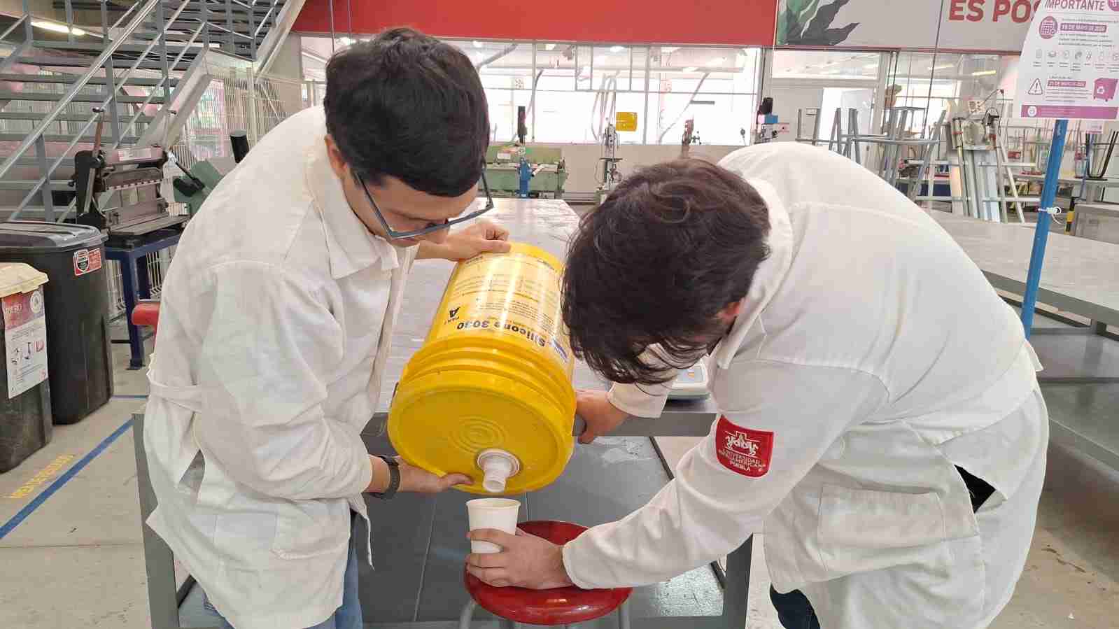
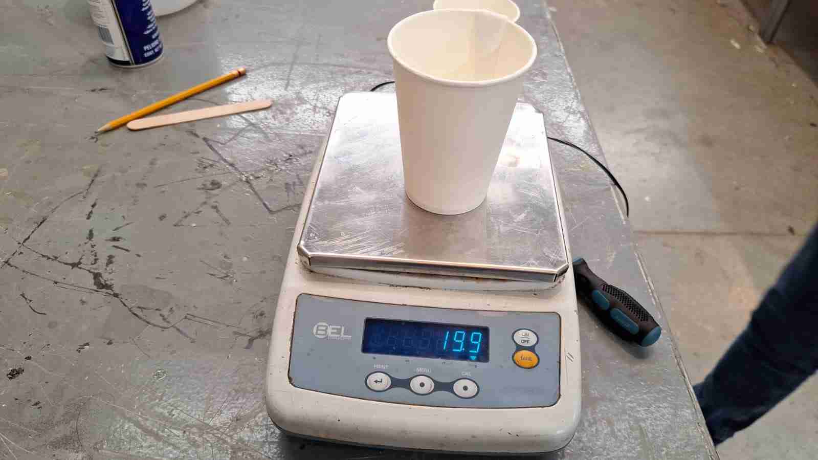
I used Silicone 3030 as the casting material for my mold. While handling the materials, I wore a lab coat and steel-toed boots for safety. Silicone 3030 has a mix ratio of 100A to 10B, which I carefully measured using an electronic scale.
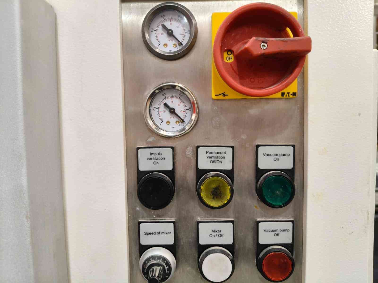
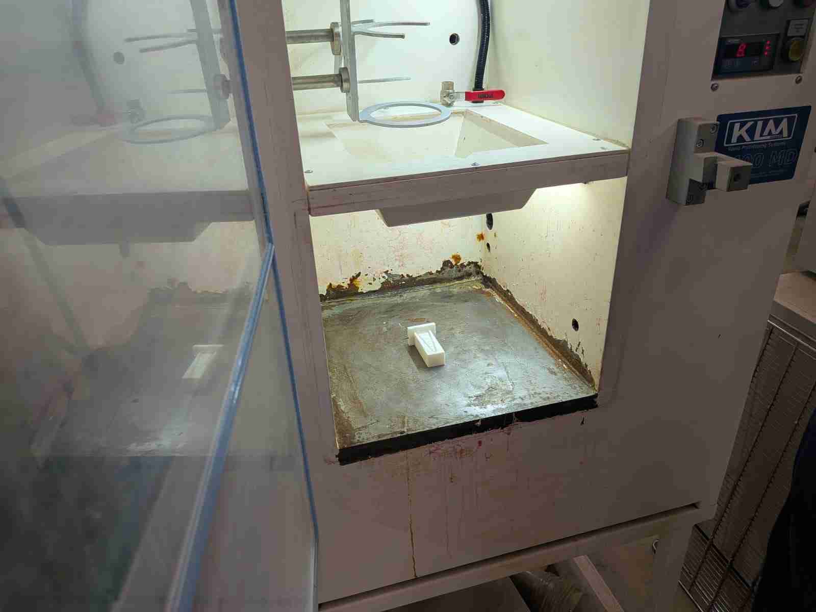
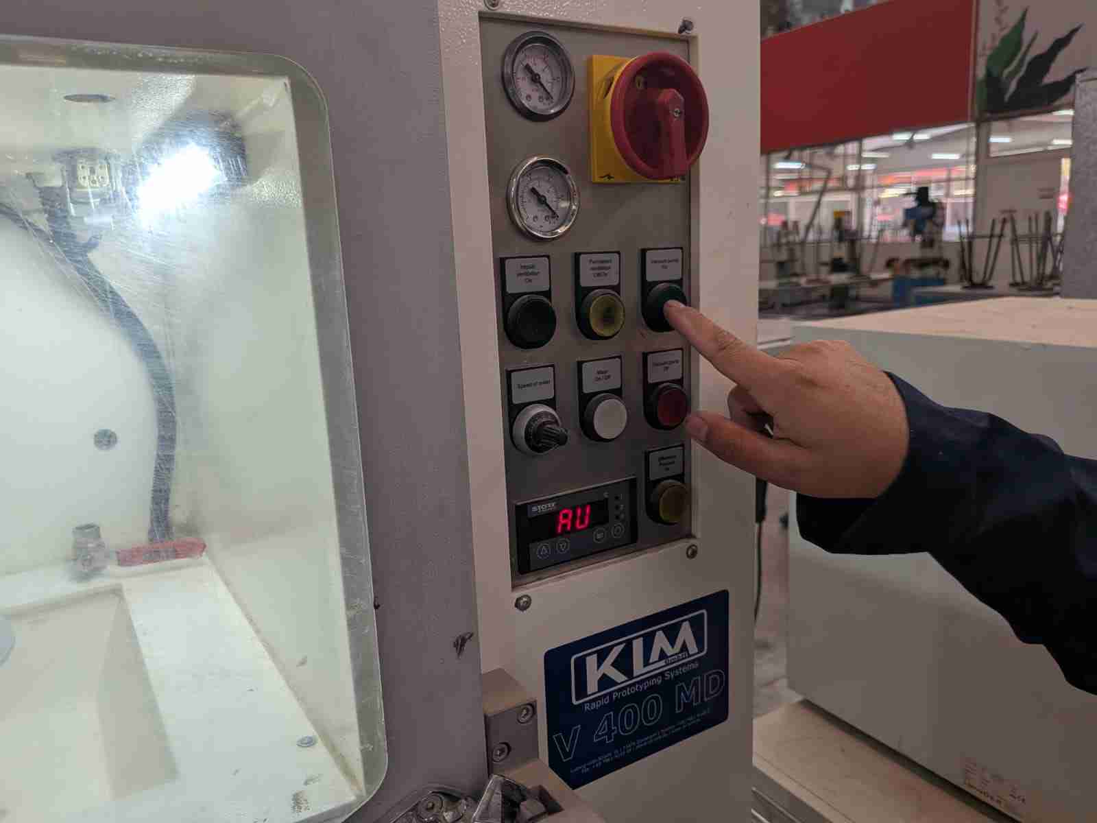
I also used a vacuum chamber to eliminate the bubbles that formed during the mixing and casting of the material. The vacuum machine at FabLab Ibero Puebla is a KLM 400 MD, which I found to be quite straightforward to use. To vacuum a piece, you just need to place the mold inside the chamber, turn it on, press the "Vacuum pump on" button, and wait until the vacuum starts taking effect in the cast material. It is normal to hear bubbles popping, but if the material starts pouring out of the mold, you can press the "Impulse ventilation on" button. After confirming that there are no bubbles, the vacuum pump can be turned off, and the material and pressure can be released by pressing the "Impulse ventilation" button.
5. Solidification and demolding
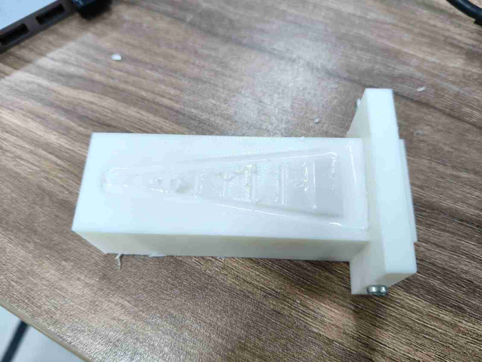
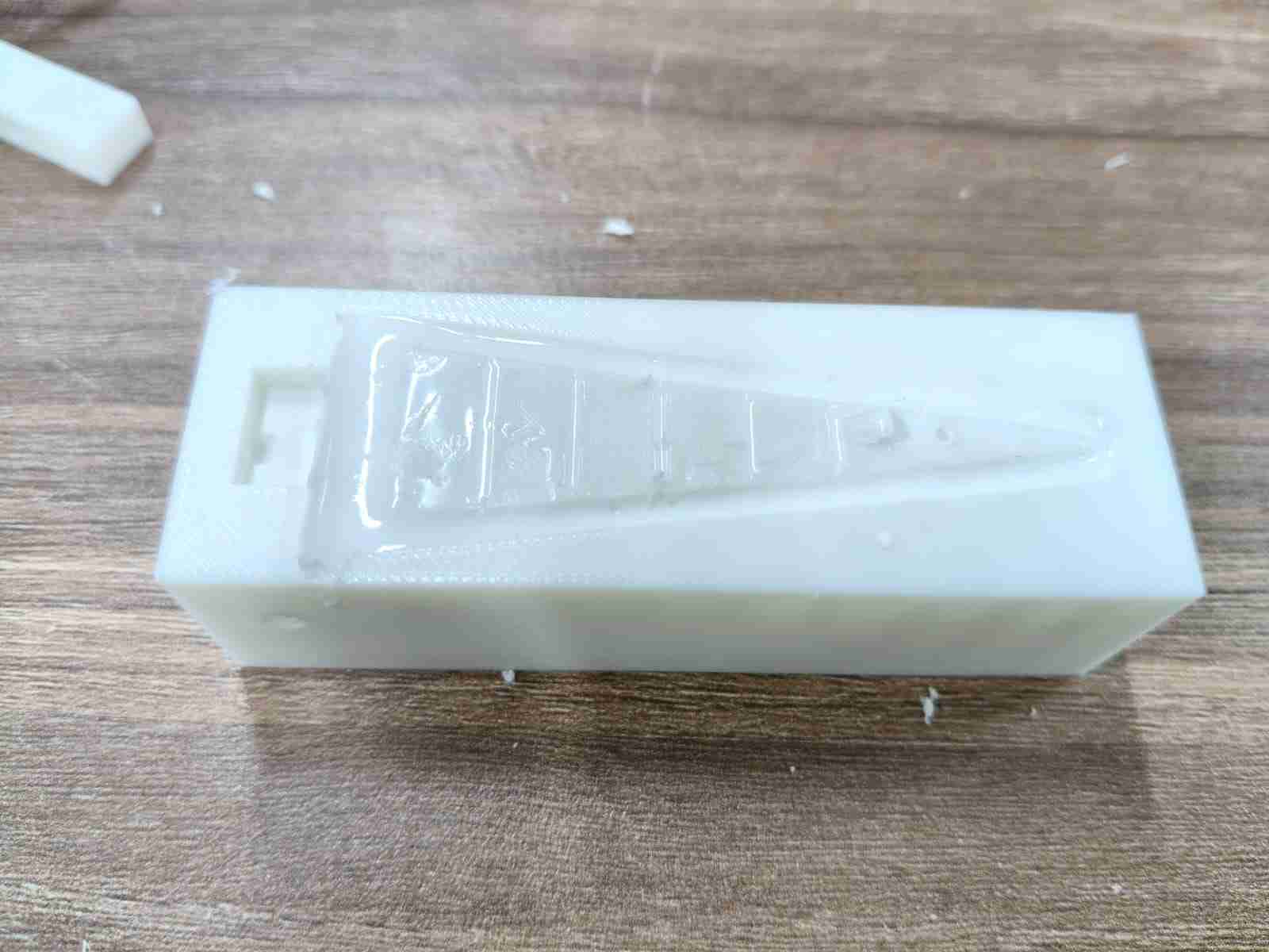
After waiting for six hours, I was finally able to begin demolding my piece by first removing the holder. The absence of any liquid material after I unscrewed it was a good sign that everything had solidified correctly. Now, I needed to carefully remove my Fin Ray spoke to avoid breaking any of the middle beams.
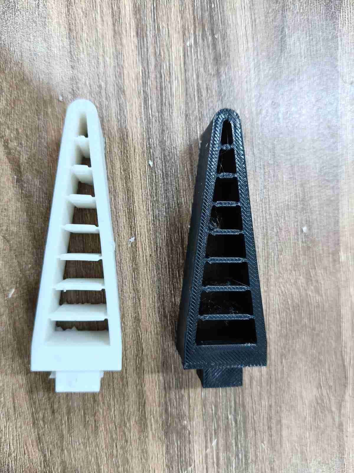
The molded Fin-Ray displayed the characteristic bending motion typical of this type of spoke. I decided to compare its bending with that of one of my original Fin Ray spokes (black). Although the molded Fin Ray was able to bend, it lacked the firmness of its TPU counterpart.
6. Files
Here are the downloadable files for this week:
CAD files for Week 13Reflection
This was my first time molding a piece. I had learned to use a 3D printer before diving into molding and casting, so I knew this experience would provide insight into traditional methods. I initially intended to use this assignment to develop my workflow for the Fin Rays for my final project. Although I managed to create a Fin-Ray appendage, it takes six hours for a single spoke to solidify, and the demolding process is quite tricky. Therefore, I will stick to my 3D-printed Fin Ray spokes.