Final Project
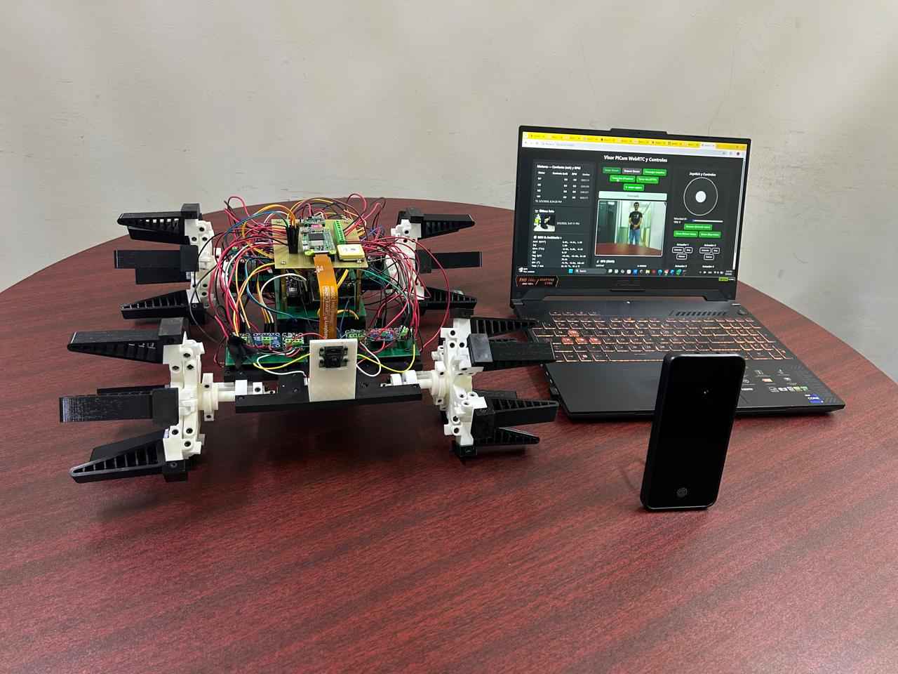
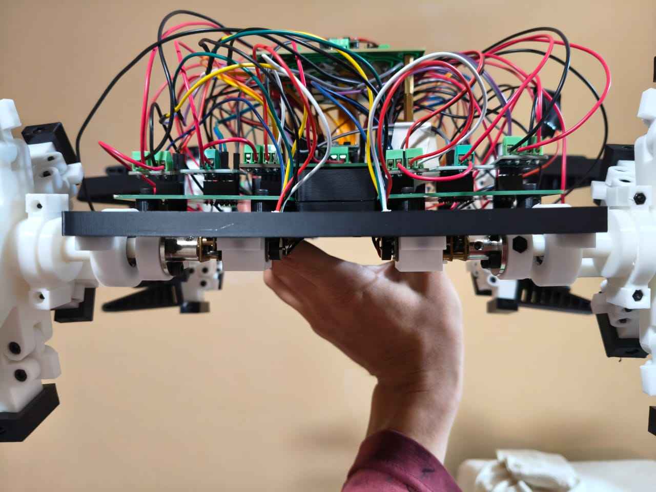
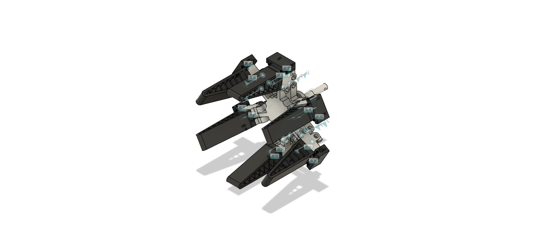
My initial idea for the final project is an RTK-guided ground robot equipped with a camera and an open architecture for modular sensor packages, based on a prototype I developed during the latter half of my master's degree. This prototype employs transforming fin-ray wheel-legs instead of traditional wheels to traverse obstacles more effectively. It supports a wheel-leg mode for climbing rigid obstacles and a compliant mode in which the fin-ray appendages contact the ground for superior terrain traversal. Additionally, it includes a XIAO GNSS module for positioning and a camera for enhanced situational awareness.
The research group I am currently part of focuses on developing Triboelectric Nanogenerators as self-powered sensors for environmental monitoring and precision agriculture. Thus, I aim to provide a robotic platform that serves as a testbed for these sensors in real-world outdoor navigation and data collection scenarios.
For this project, what do I plan to do?
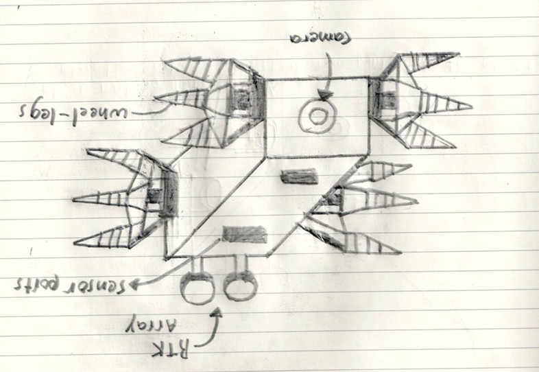
- Redesign the robot's structure to enclose and protect the electronics from environmental factors like dust and humidity.
- Incorporate RTK GNSS navigation for precise positioning, with the robot acting as a "rover" receiving fixes from a "base" station. This will enable autonomous navigation to specific locations on a map.
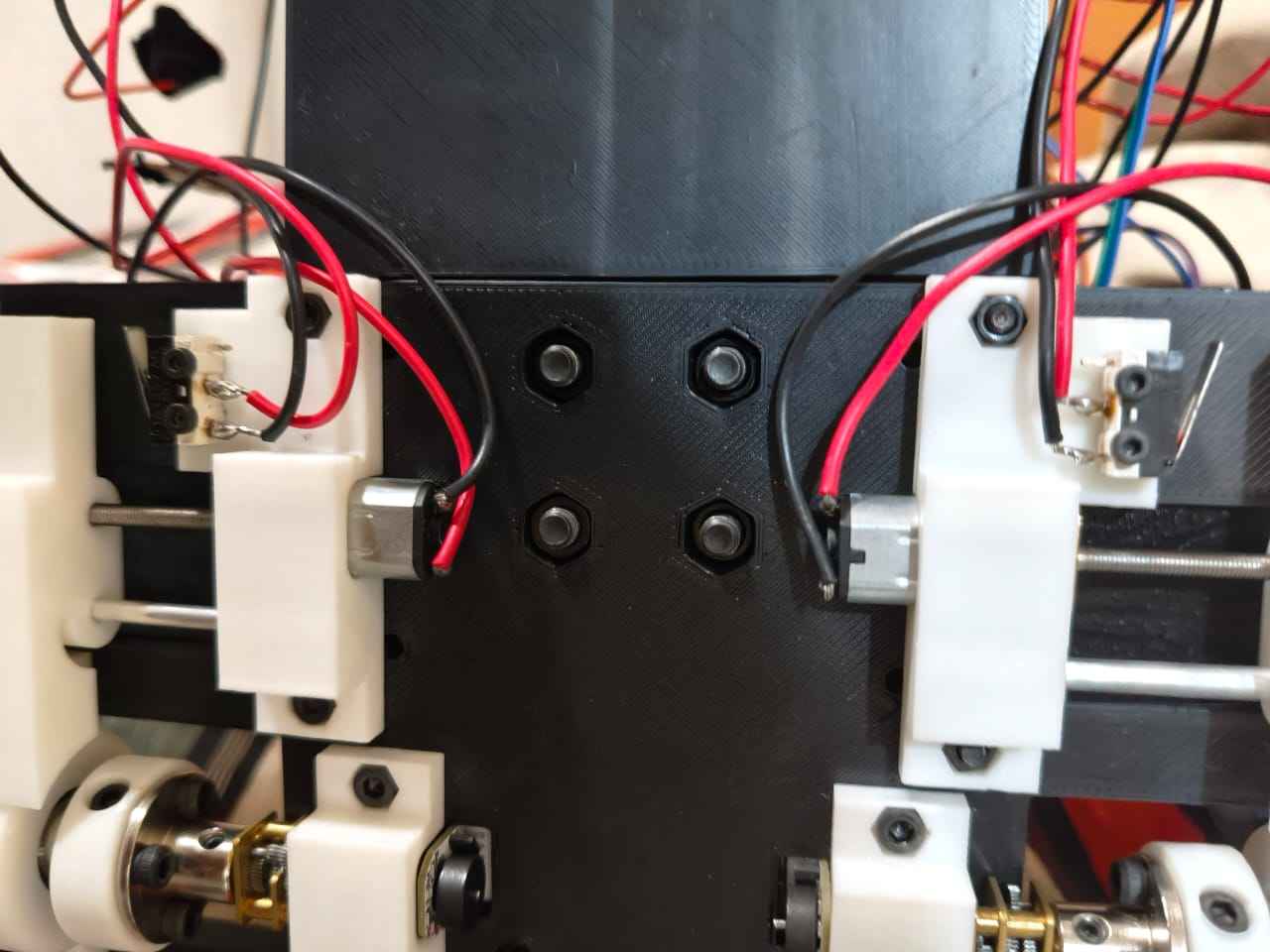
- Rework the wheel-leg transformation mechanism to reduce weight and cabling. Currently, each wheel features a linear worm drive actuator for mode toggling and a pair of limit switches for position feedback.
- Redesign the electronics boards to enable easy integration of additional sensor packages, similar to Arduino Shield Boards.
- Integrate long-range communication equipment to extend the data exchange range.
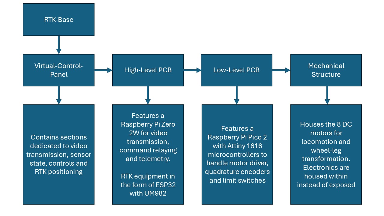
Project block diagram
Tasks to be completed
1. Electronics Design and Production
- Determine how many Attiny 1616 or 1614 chips are necessary to complement a Raspberry Pi Pico 2 in controlling motors for wheel-leg transformations. The Attiny boards should be able to receive commands for activating the motors and stopping them when a limit switch comes active.
- Test the Programmable I/O (PIO) blocks of the Raspberry Pi Pico 2 for encoder quadrature signal reading. PIO blocks could offload processing from the main CPU.
- Define how the PCBs will connect to each other. DuPont cables are not a reliable solution for this; they tend to come loose and are brittle.
- Design the layouts for the new PCBs; these designs should take into account the interfaces between PCBs and the means of attaching them to the mechanical structure of the robot. PCB design should also allow for easy integration of additional modules.
- Manufacture the new PCBs.
2. Mechanical Design and Fabrication
- Design a new wheel-leg pad to be manufactured through the molding and casting process. As TPU is already present in the design, a different material could help the robot adapt to different terrains.
- Redesign motor holders to prevent backsliding.
- Redesign the mechanical structure of the robot to prevent buckling caused by the continous transformation of the wheel-legs.
- Redesign the mechanical structure so it can house the electronics of the robot while leaving the RTK antennae exposed.
- 3D print the revised components and manufacture the molds.
3. Programming and debugging
- Incorporating RTK data visualization into the robot control panel, this will involve connecting the ESP32 with the UM982 module to the Raspberry Pi via UART.
- Program the Raspberry Pi Pico and Attinys to handle movement commands for going straight, backwards or turning via front-panel commands.
- Test the compatibility of platforms like ArduPilot Rover for autonomous navigation.
4. System integration and documentation
- Assemble the electronics and mechanical components.
- Document each milestone and failure.
Schedule
Week 1: 5/4/2026-5/11/2026
- Determine Attiny chips needed for motor control.
- Test the Programmable I/O (PIO) blocks of the Raspberry Pi Pico 2.
- Define PCB connections.
- Redesign motor holders.
- PCB design
Week 2: 5/11/2026-5/18/2026
- Design wheel-leg pads.
- PCB manufacturing.
- Redesign robot mechanical structure.
- 3D print the revised components and manufacture the molds.
Week 3: 5/18/2026-5/25/2026
- Manufacture molded parts.
- Integrate the PCBs and mechanical components.
- Program V-panel and movement routines.
Week 4: 5/25/2026-6/1/2026
- Test RTK equipment and the ability of the robot to get fixes.
- Test the robots ability to follow a trajectory through the use of RTK data.
What I have so far...
I have tested my Attiny 1616 and DRV8871 PCBs.
const uint8_t IN1 = PIN_PA1;
const uint8_t IN2 = PIN_PA2;

uint8_t speedValue = 180;  // 0 to 255

void motorStop() {
  digitalWrite(IN1, LOW);
  digitalWrite(IN2, LOW);
}

void motorForward(uint8_t pwm) {
  analogWrite(IN1, pwm);
  digitalWrite(IN2, LOW);
}

void motorReverse(uint8_t pwm) {
  digitalWrite(IN1, LOW);
  analogWrite(IN2, pwm);
}

void setup() {
  pinMode(IN1, OUTPUT);
  pinMode(IN2, OUTPUT);

  motorStop();

  Serial.begin(9600);
  delay(100);

  Serial.println("Ready. F, R, S, 0-9 for speed");
}

void loop() {
  if (Serial.available() > 0) {
    char cmd = Serial.read();

    if (cmd == 'F' || cmd == 'f') {
      motorForward(speedValue);
      Serial.print("Forward, PWM=");
      Serial.println(speedValue);
    }
    else if (cmd == 'R' || cmd == 'r') {
      motorReverse(speedValue);
      Serial.print("Reverse, PWM=");
      Serial.println(speedValue);
    }
    else if (cmd == 'S' || cmd == 's') {
      motorStop();
      Serial.println("Motor stopped");
    }
    else if (cmd >= '0' && cmd <= '9') {
      speedValue = map(cmd - '0', 0, 9, 0, 255);
      Serial.print("New PWM speed=");
      Serial.println(speedValue);
    }
    else if (cmd == '\n' || cmd == '\r') {
      // ignore
    }
    else {
      Serial.print("Invalid command: ");
      Serial.println(cmd);
    }
  }
}
Development
Wheel-Leg Closed position
Wheel-Leg Open position