Week 12 - Mechanical Design and Machine Design
This week's assignment involved collaborating with fellow Fab Academy students to create a CNC machine. Initially, our group aimed to develop an automated pipetting machine; however, we soon realized that this project was too ambitious given the time constraints of Fab Academy. Consequently, we decided to pivot and focus on building a light-painting machine instead. For more details about overall project development, please click here .
Work log
Completed tasks
- Participated in designing a machine that encompasses mechanism, actuation, automation, and application.
- Engaged in every stage of the machine's development cycle.
- Documented my individual contributions.
1.What is a CNC Machine nad what was the first proposal from my team?
First of all, what is a CNC machine? CNC stands for Computer Numerical Control. Instead of a person manually moving a tool, a computer follows programmed instructions—usually written in G-code—to move actuators along various axes. I always thought that a CNC machine primarily involved a cutting tool automatically moving along different axes, so learning this definition was an eye-opening moment.
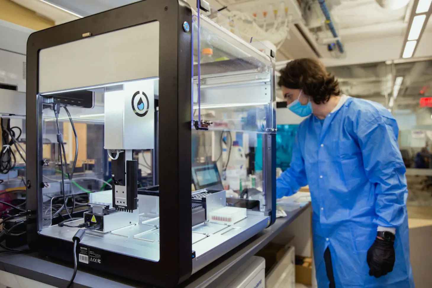
This week's assignment involved designing and fabricating a CNC machine (not a milling machine). My team and I took on the challenge of creating a pipetting machine based on the OT-2 by Opentrons. The Opentrons OT-2 is a benchtop liquid-handling robot designed to automate repetitive pipetting tasks that researchers typically perform by hand. In simpler terms, it functions as a CNC machine for liquids: rather than moving a cutting tool along X, Y, and Z axes, it moves pipettes over labware to transfer precise amounts of liquid between tubes, plates, reservoirs, and other containers.
While lab personnel are capable of performing the tasks that the OT-2 handles, this machine excels at precisely placing small droplets at specific positions in a Petri dish, particularly when the required spacing is in the millimeter range.
2. What were my contributions for this first proposal?
I was not in Puebla when my team first gathered to discuss and assign tasks for our pipetting machine project. However, I maintained constant communication with my teammates to explore different options for each stage of development. At the outset, I proposed that the motion system of our machine be based on a gantry design using screw stepper motors instead of a pulley system. My reasoning for this choice was that handling substances requires precision and repeatability, rather than speed. My team agreed with this reasoning, and we delegated tasks based on each member's preferences. Since my teammates were able to work at FabLab Ibero Puebla with the available tools, machines, and components, I began considering how we could actuate the pipette with precision and consistency.
My main concern was how to actuate the pipette in a precise manner. Although I had used pipettes before, they were nothing like the ones my team and I were given for this assignment. I knew I had to come up with a solution quickly, and it needed to be easy to implement, since I was also aware that I could contribute to other areas of the project. After all, the pipetting machine was not a simple, inexpensive task.
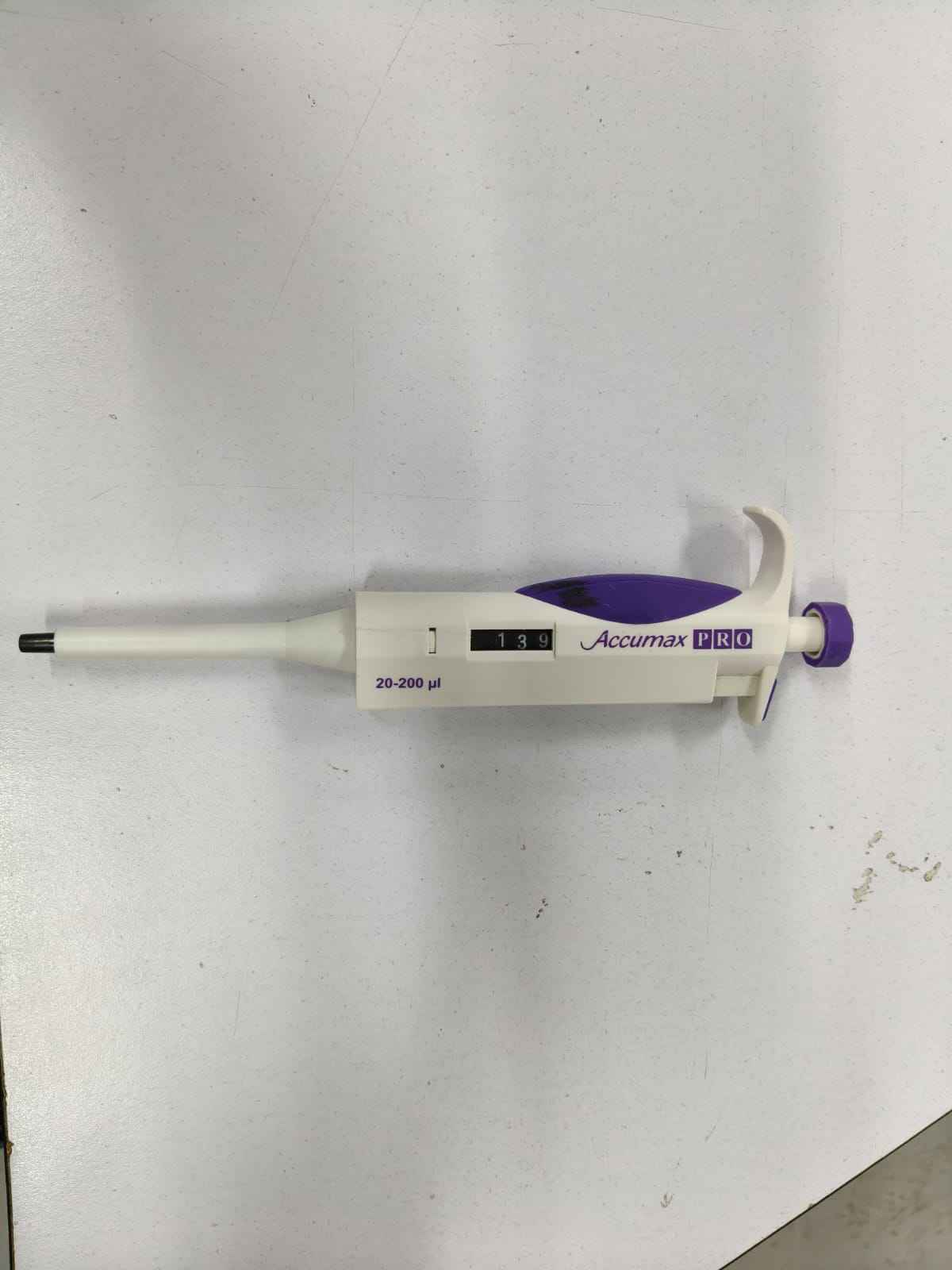
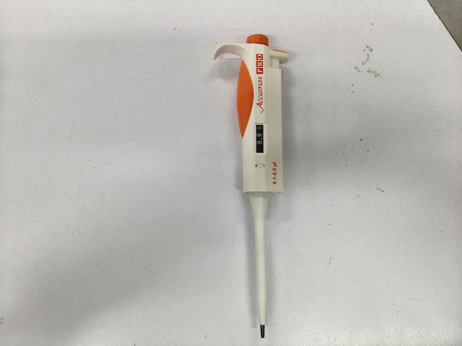
To start working, my team and I were given an adjustable micropipette, specifically an Accumax PRO 20-200 µL pipette, which is used to measure and transfer small liquid volumes, usually in biology, chemistry, microbiology, or medical labs. The 20–200 µL label indicates this pipette can accurately measure volumes between 20 microliters and 200 microliters. A microliter, written as "µL," is a minuscule quantity: 1000 µL = 1 mL. So, in simpler terms, this pipette handles volumes from 0.020 mL to 0.200 mL. This type of pipette is usually an air-displacement pipette; its inner workings include a piston. When the plunger is pressed, the piston moves and pushes air out; when the plunger is released, the piston moves back and creates suction, pulling liquid into the disposable tip. A liquid does not enter directly into the pipette body; it stays inside a plastic pipette tip, which attaches to the black/white cone at the front.
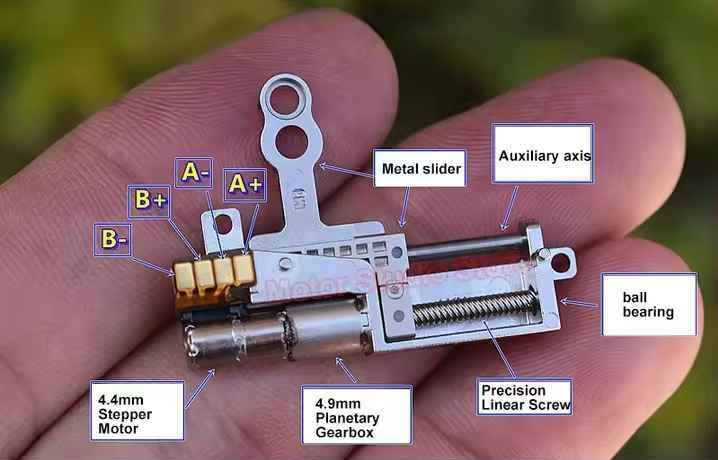
Once my teammates showed me the pipette, I asked whether it was necessary to fully press the plunger to operate it. To my relief, they confirmed that the plunger functioned properly when pressed only 8 mm. Fortunately, I had a surplus of three different 8 mm microstepper linear actuators. I packed them, along with the necessary circuitry, and headed to Puebla. My first task was to determine which of the actuators had enough force to reliably pull the plunger.
I acquired two variants of the microstepper linear actuators from the same vendor, who categorizes them as A1 and A2. These linear actuators can be driven using a TB6612FNG breakout board, which provides enough output pins to handle two independent DC motors or both windings of a bipolar stepper motor. I chose this circuit because other available stepper motor drivers, like the DRV8825, can only handle stepper motors with a minimum operating voltage of 6 volts. Unfortunately, all three linear actuator variants operated at 5 volts, so the TB6612FNG was the suitable choice.
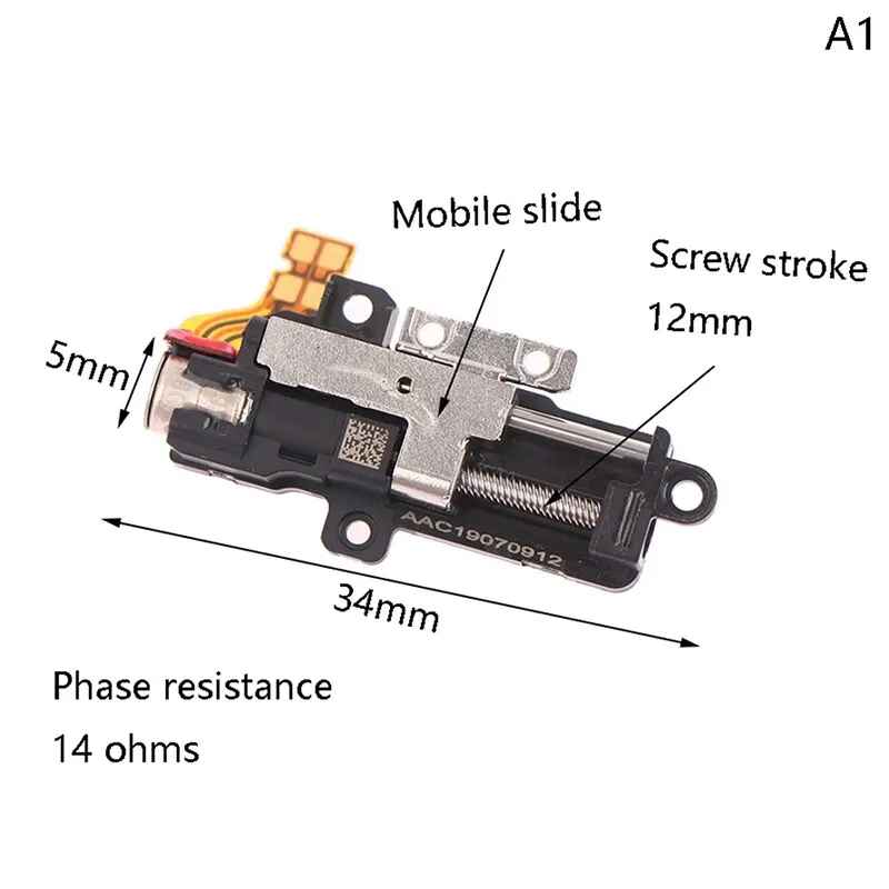
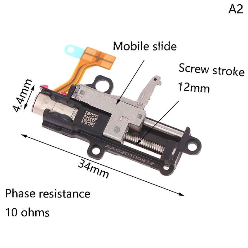
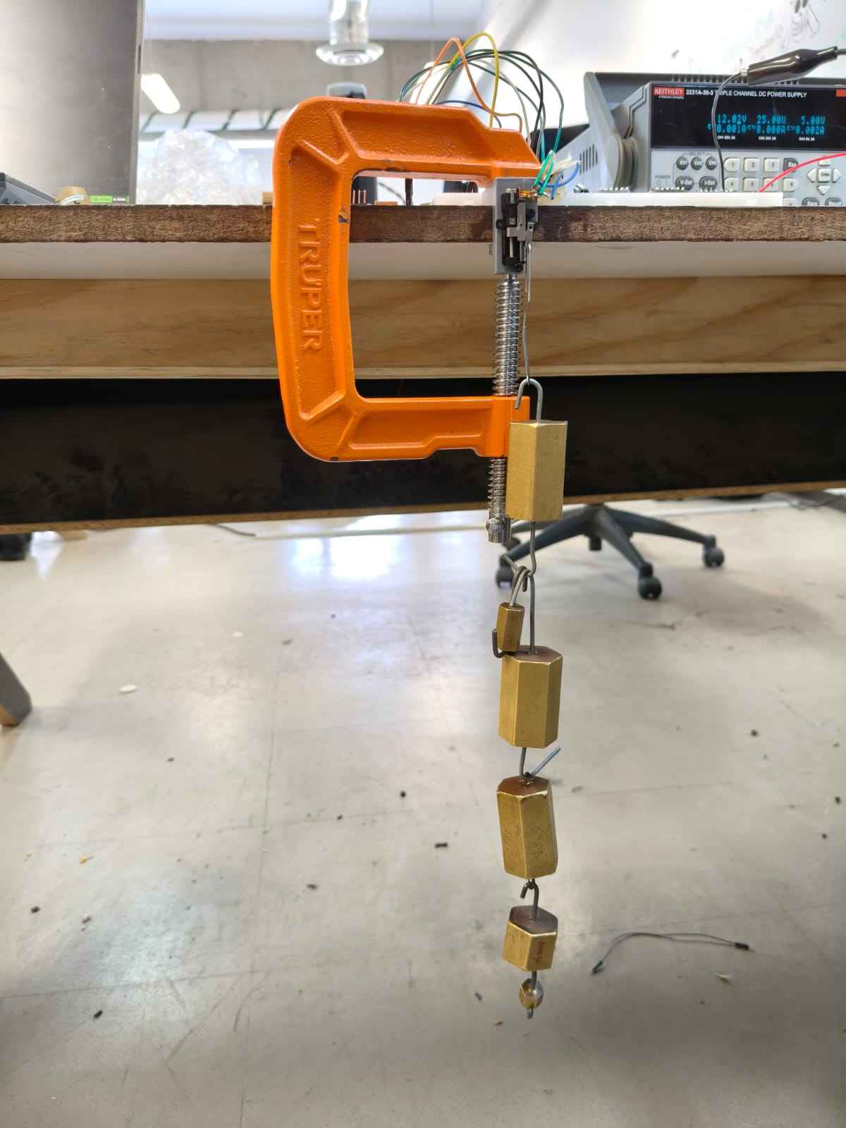
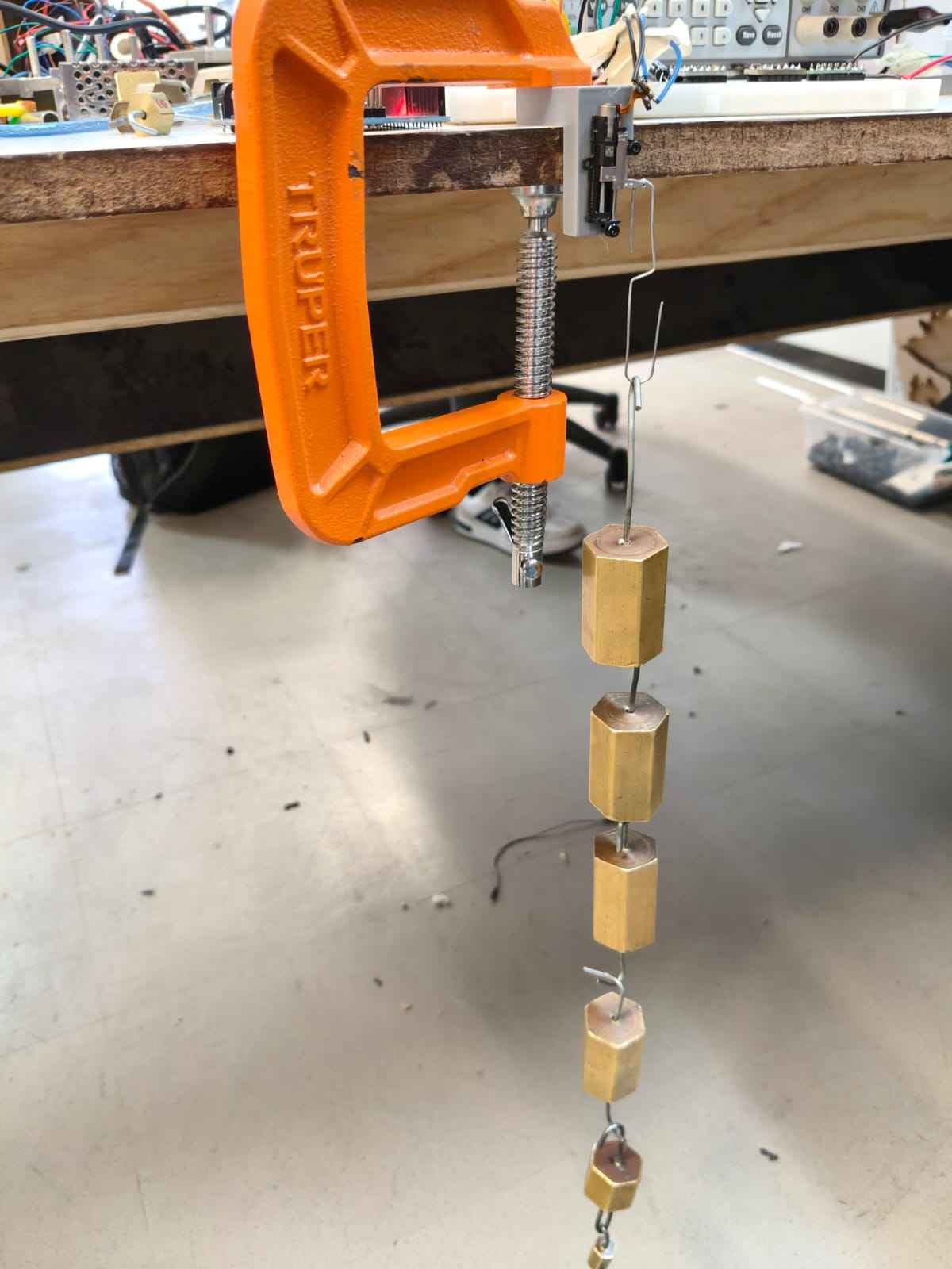
I tested the microlinear actuators using an Arduino board for quick debugging. I first evaluated the A1 and A2 variants with calibration weights to determine their maximum pull-force. I 3D-printed a stand for the A1 and A2 variants and gradually added more weight until the motors could no longer pull. Through these tests, I found that the A1 variant could pull 850 grams, while the A2 could pull 970 grams. Both options looked promising.
I asked ChatGPT for assistance in writing the code to test the motors. The core function of this code is the sequence of winding activation. Since the TB6612FNG requires its STBY signal to be HIGH to operate, it is kept at that level for the duration of the sequence. Both PWM pins are maintained at a 100% duty cycle, while the AIN1, AIN2, BIN1, and BIN2 pins receive activation signals to energize the motor windings. Each of the three motors required 2,500 steps to complete a sequence. Stepper motors cannot accelerate instantly from rest to high speed. If the delay between steps is too short, the motor may vibrate instead of moving, skip steps, lose torque, stall, or move inconsistently. A longer delay allows the rotor more time to physically reach each step position before the next magnetic field change occurs.
            // Winding A
            const int AIN1 = 5;
            const int AIN2 = 4;
            const int PWMA = 3;

            // Winding B
            const int BIN1 = 6;
            const int BIN2 = 7;
            const int PWMB = 9;

            const int STBY = 8;

            const int totalSteps = 2500; // 8 mm of travel
            const int stepDelay = 1;    // Time between steps in ms

            // Full-step sequence
            // Order: AIN1, AIN2, BIN1, BIN2
            const int sequence[4][4] = {
              {1, 0, 1, 0}, // Step 1
              {0, 1, 1, 0}, // Step 2
              {0, 1, 0, 1}, // Step 3
              {1, 0, 0, 1}  // Step 4
            };

            void setup() {
              pinMode(AIN1, OUTPUT);
              pinMode(AIN2, OUTPUT);
              pinMode(PWMA, OUTPUT);

              pinMode(BIN1, OUTPUT);
              pinMode(BIN2, OUTPUT);
              pinMode(PWMB, OUTPUT);

              pinMode(STBY, OUTPUT);

              digitalWrite(STBY, HIGH); // Enables the driver

              // Enable both motor channels at full power
              analogWrite(PWMA, 255);
              analogWrite(PWMB, 255);

              Serial.begin(9600);
              Serial.println("Ready to receive commands:");
              Serial.println("f = forward");
              Serial.println("b = backward");
              Serial.println("s = stop / turn off motor");
            }

            void loop() {
              if (Serial.available()) {
                char command = Serial.read();

                if (command == 'f') {
                  Serial.println("Moving forward...");
                  moveSteps(totalSteps, stepDelay);
                  Serial.println("Forward movement complete.");
                }
                else if (command == 'b') {
                  Serial.println("Moving backward...");
                  moveSteps(-totalSteps, stepDelay);
                  Serial.println("Backward movement complete.");
                }
                else if (command == 's') {
                  Serial.println("Motor turned off.");
                  turnOffMotor();
                }
              }
            }

            void moveSteps(int steps, int delayTime) {
              // Make sure the driver and motor channels are enabled
              digitalWrite(STBY, HIGH);
              analogWrite(PWMA, 255);
              analogWrite(PWMB, 255);

              int direction = 1;

              if (steps < 0) {
                direction = -1;
                steps = -steps;
              }

              for (int i = 0; i < steps; i++) {
                int stepIndex;

                if (direction == 1) {
                  stepIndex = i % 4;
                } else {
                  stepIndex = 3 - (i % 4);
                }

                digitalWrite(AIN1, sequence[stepIndex][0]);
                digitalWrite(AIN2, sequence[stepIndex][1]);
                digitalWrite(BIN1, sequence[stepIndex][2]);
                digitalWrite(BIN2, sequence[stepIndex][3]);

                delay(delayTime);
              }
            }

            void turnOffMotor() {
              digitalWrite(AIN1, LOW);
              digitalWrite(AIN2, LOW);
              digitalWrite(BIN1, LOW);
              digitalWrite(BIN2, LOW);

              analogWrite(PWMA, 0);
              analogWrite(PWMB, 0);

              digitalWrite(STBY, LOW); // Puts the TB6612FNG in standby mode
            }
Unfortunately, neither option could produce enough force to press the plunger. As a result, I had to use the third microstepper variant, which featured a planetary gearhead. This linear actuator was able to reliably pull the plunger past 8 mm, but it generated a significant amount of heat. Still, I considered the issue resolved for the time being.
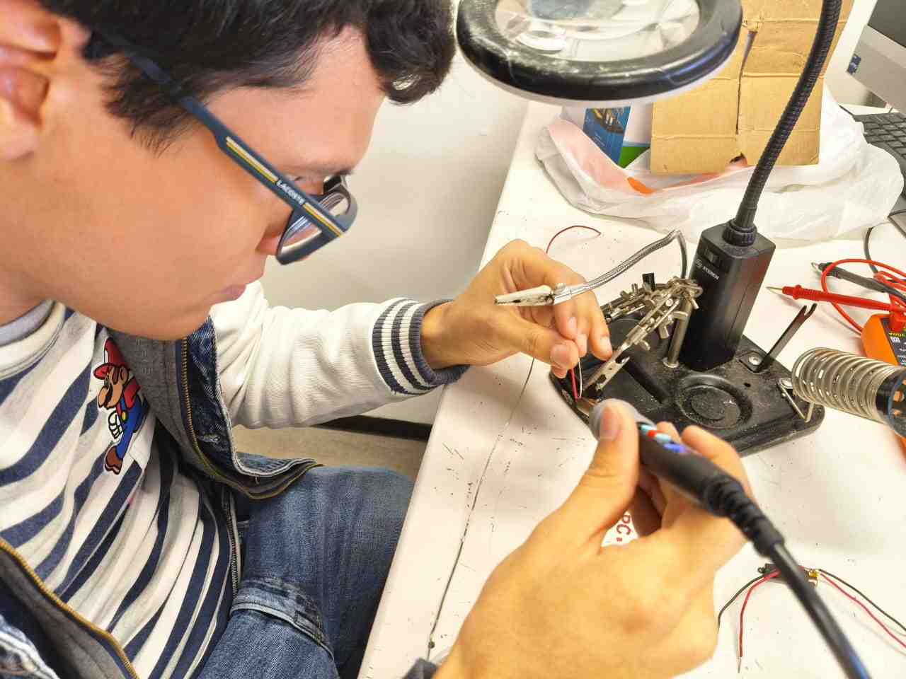
It is important to note that none of the three linear actuator variants come with wires pre-soldered to their terminals; it is up to the user to complete the connections before the actuators can be used.
The following videos show the testing of the linear actuators movement before using the calibration weights:
My relief was short-lived, as the next day we were informed that we would be using an Accumax PRO 0.1–2.5 µL pipette instead of the one we were originally given. The reason for this change was that our machine needed to deliver 1 µL per drop, and this new pipette required even greater force to operate its plunger. Unfortunately, the third linear actuator was unable to meet this requirement. As a result, I decided to try using servomotors instead.
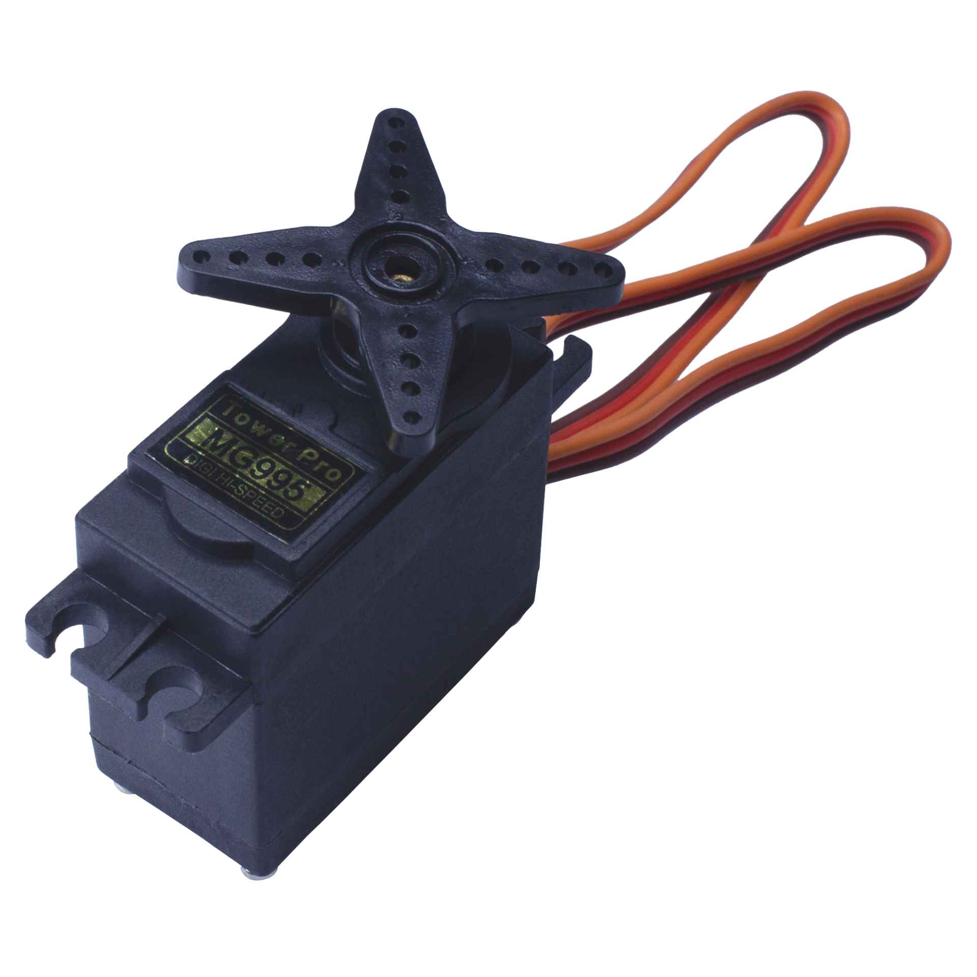
The servomotor I chose was the MG995. Different vendors list slightly different values for stall torque and operating voltage, which is common with MG995 servos due to the many clones and variants available. Some datasheets specify 8.5 kg·cm at 4.8 V and 10 kg·cm at 6 V, while others report around 9.4 kg·cm at 4.8 V and 11 kg·cm at 6 V. In any case, these values are greater than those I observed with the microstepper linear actuators.
One advantage of using a servomotor over a microlinear actuator is the simplicity of the circuitry. To properly actuate the pipette, our system would have required two micro linear actuators, one for the main plunger and another for ejecting the used plastic tip without manual contact. This would have necessitated two TB6612FNG drivers. Neither a single ESP32 nor a Raspberry Pi Pico 2 has enough pins to handle multiple TB6612FNG drivers and stepper motor drivers. Addressing this limitation would have required adding another microcontroller, such as an ATtiny1616, further increasing system complexity. Fortunately, using two servomotors only requires two PWM outputs, allowing the entire system to be controlled by a single ESP32 board.
With the assistance of ChatGPT, I wrote another code to test servo positions and store their coordinates. This allowed me to determine whether the servomotors could effectively manipulate the pipette and to identify the optimal positions for operation.
            #include

            Servo myServo;

            const int servoPin = 18;

            int positionA = 0;
            int positionB = 90;
            int currentPosition = 0;

            void setup() {
              Serial.begin(115200);

              myServo.setPeriodHertz(50);
              myServo.attach(servoPin, 500, 2400);

              myServo.write(currentPosition);

              Serial.println("Servo ready.");
              Serial.println("Available commands:");
              Serial.println("a = save current position as position A");
              Serial.println("b = save current position as position B");
              Serial.println("1 = move to position A");
              Serial.println("2 = move to position B");
              Serial.println("0-180 = move servo to that angle");
            }

            void loop() {
              if (Serial.available() > 0) {
                String input = Serial.readStringUntil('\n');
                input.trim();

                if (input == "a") {
                  positionA = currentPosition;
                  Serial.print("Position A saved: ");
                  Serial.println(positionA);
                }
                else if (input == "b") {
                  positionB = currentPosition;
                  Serial.print("Position B saved: ");
                  Serial.println(positionB);
                }
                else if (input == "1") {
                  currentPosition = positionA;
                  myServo.write(currentPosition);

                  Serial.print("Moving to position A: ");
                  Serial.println(currentPosition);
                }
                else if (input == "2") {
                  currentPosition = positionB;
                  myServo.write(currentPosition);

                  Serial.print("Moving to position B: ");
                  Serial.println(currentPosition);
                }
                else {
                  int angle = input.toInt();

                  if (angle >= 0 && angle <= 180) {
                    currentPosition = angle;
                    myServo.write(currentPosition);

                    Serial.print("Moving to angle: ");
                    Serial.println(currentPosition);
                  } else {
                    Serial.println("Invalid command.");
                  }
                }
              }
            }
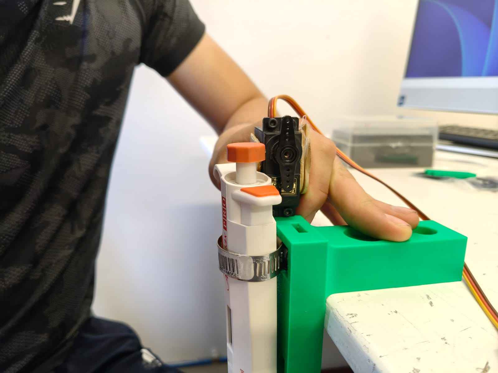
The choice of servo proved appropriate, as it could reliably actuate both the main plunger for liquid dispensing and the secondary plunger for tip ejection.
The following video demonstrates the servo pressing the main plunger to absorb liquid:
The following video shows the servo releasing the liquid:
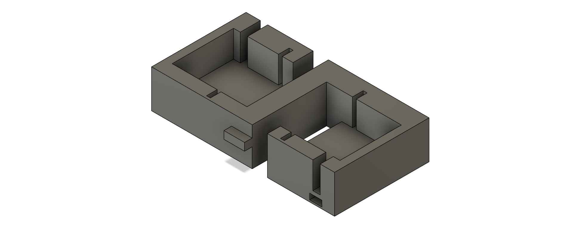
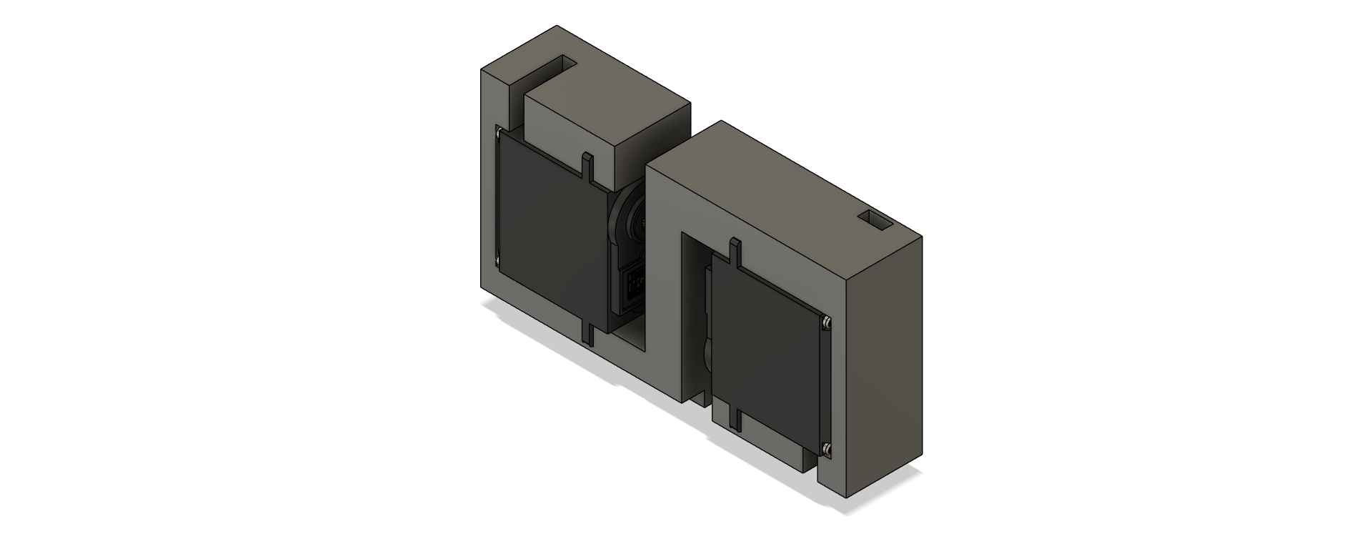
To accommodate the two servomotors required for actuating the pipette, I designed a holder component with press-fit cavities to securely position the servomotors.
3. Change of plans
Despite steady progress, my team and I encountered mounting technical challenges that required a change of direction. Instead of continuing with our original Opentrons-like machine, we decided to develop a light painting machine. More details about our decision and the technical issues involved can be found on my CNC group page. A light painting machine automates the process of light painting photography—a technique where a camera’s shutter remains open in a dark environment while a moving light source "draws" patterns or images, all captured in a long-exposure photo. Rather than manually waving a flashlight, our machine precisely controls the movement of a light source along a programmed path, allowing for the creation of intricate images or text. To achieve this, we repurposed the motion system from our Opentrons prototype, converting it into a Cartesian plotter capable of moving the light source in X and Y directions. This setup enables the machine to "draw" pixel-by-pixel images or text in the air while the camera captures the effect.
With this new project direction, I shifted my attention back to developing the machine's end-effector. My local instructor provided two 16-neopixel rings—one designated for the machine, and the other kept as a backup in case of any issues. To begin, I tested a neopixel ring using my reliable microcontroller PCB from Week 8. I powered the neopixel ring with a 12-volt supply, regulated through an MP1584 buck converter.
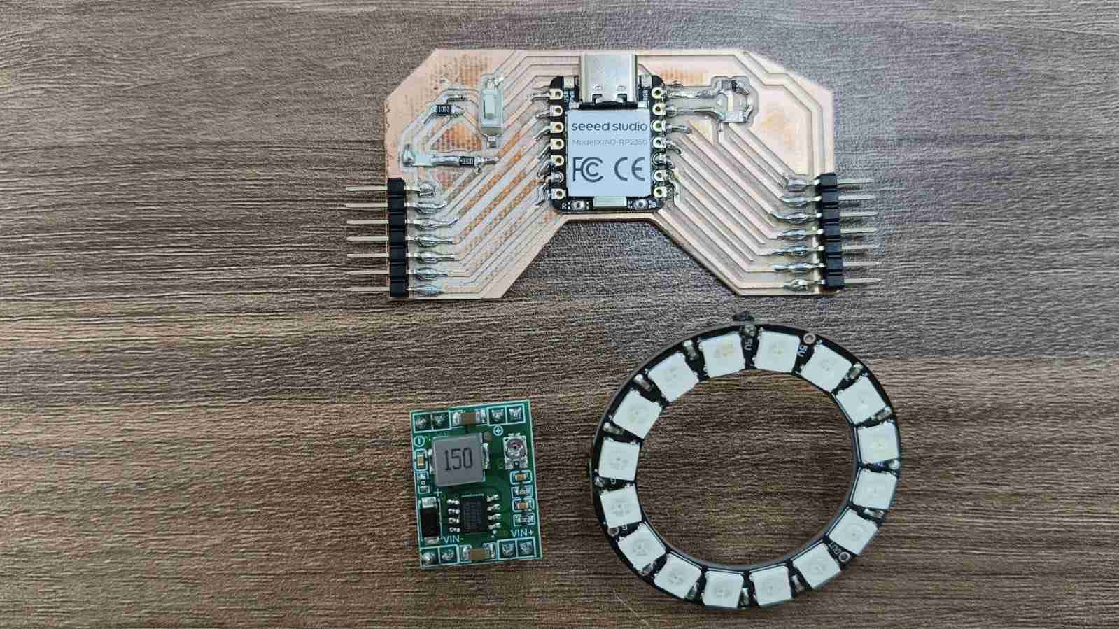
One of the advantages of neopixels is their ability to be controlled by a single data line, regardless of how many LEDs are in the ring. This means that controlling all 16 neopixels only requires one output pin, not 16. Before integrating the ring into our system, I ran a simple test to confirm that the neopixel ring was functioning correctly and undamaged. The test code—written with the help of ChatGPT—is provided below.
            #include

            #define NEOPIXEL_PIN D0
            #define NUM_PIXELS 16

            Adafruit_NeoPixel strip(NUM_PIXELS, NEOPIXEL_PIN, NEO_GRB + NEO_KHZ800);

            void setup() {
              strip.begin();
              strip.setBrightness(50);   // brightness from 0 to 255
              strip.show();              // turns all pixels off at startup
            }

            void loop() {
              // Red
              fillColor(strip.Color(255, 0, 0));
              delay(1000);

              // Green
              fillColor(strip.Color(0, 255, 0));
              delay(1000);

              // Blue
              fillColor(strip.Color(0, 0, 255));
              delay(1000);

              // White
              fillColor(strip.Color(255, 255, 255));
              delay(1000);

              // Off
              fillColor(strip.Color(0, 0, 0));
              delay(1000);

              // One-by-one effect
              colorWipe(strip.Color(255, 100, 0), 80);
              colorWipe(strip.Color(0, 0, 0), 40);
            }

            void fillColor(uint32_t color) {
              for (int i = 0; i < NUM_PIXELS; i++) {
                strip.setPixelColor(i, color);
              }
              strip.show();
            }

            void colorWipe(uint32_t color, int waitMs) {
              for (int i = 0; i < NUM_PIXELS; i++) {
                strip.setPixelColor(i, color);
                strip.show();
                delay(waitMs);
              }
            }
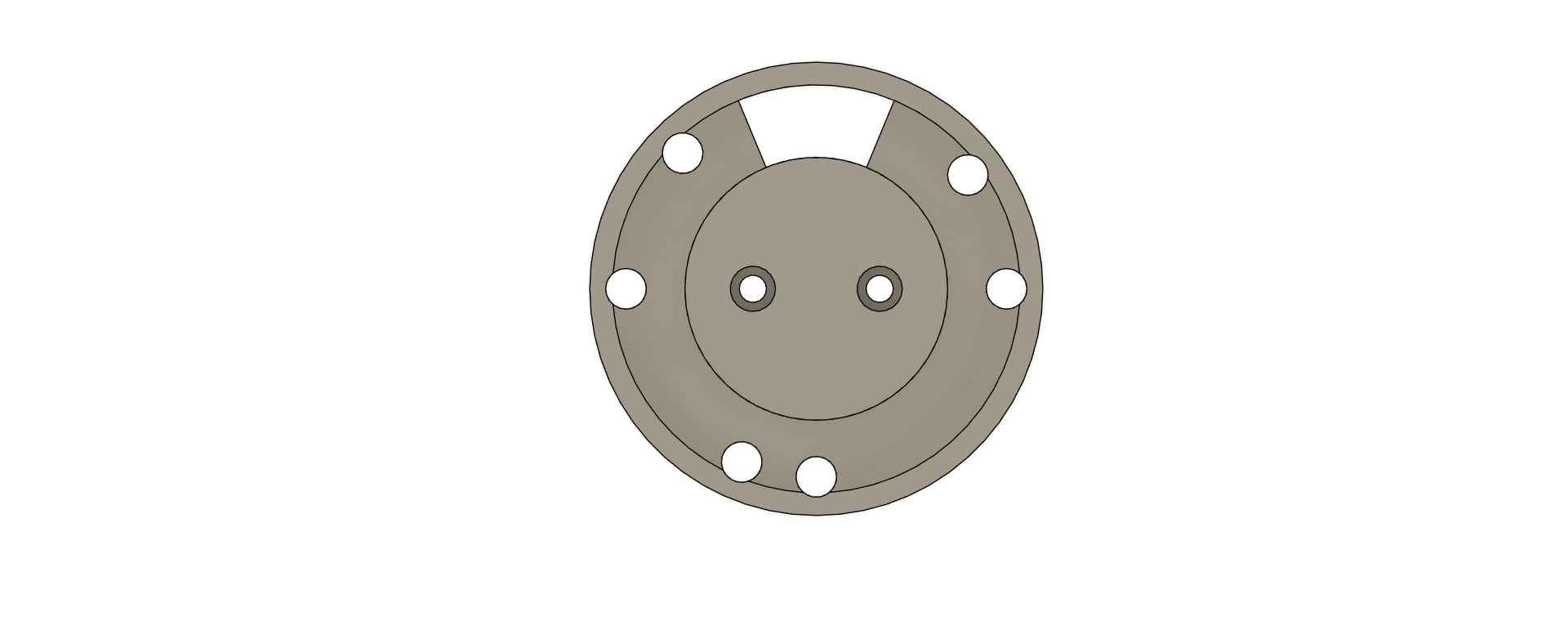
After confirming that the Neopixel ring was fully functional, I moved on to designing a holder for it. To start, I downloaded a 3D model closely matching the 16-neopixel ring I was using. You can download the model by clicking here .
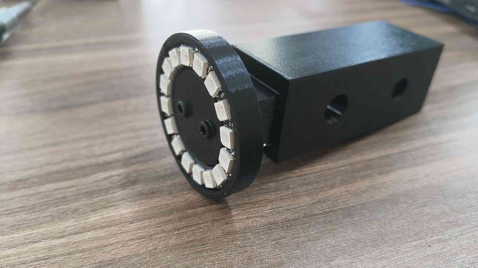
I designed the machine’s end effector to be manufactured using 3D printing. The ring holder was created as a single piece, featuring built-in cavities to allow male pin headers to pass through easily. I also left a section of the holder hollow, making it easier to remove the Neopixel ring with a pen or fingers if necessary. These design choices were made to simplify both the connection between the Neopixel ring and the microcontroller, as well as to facilitate easy replacement in case of damage.
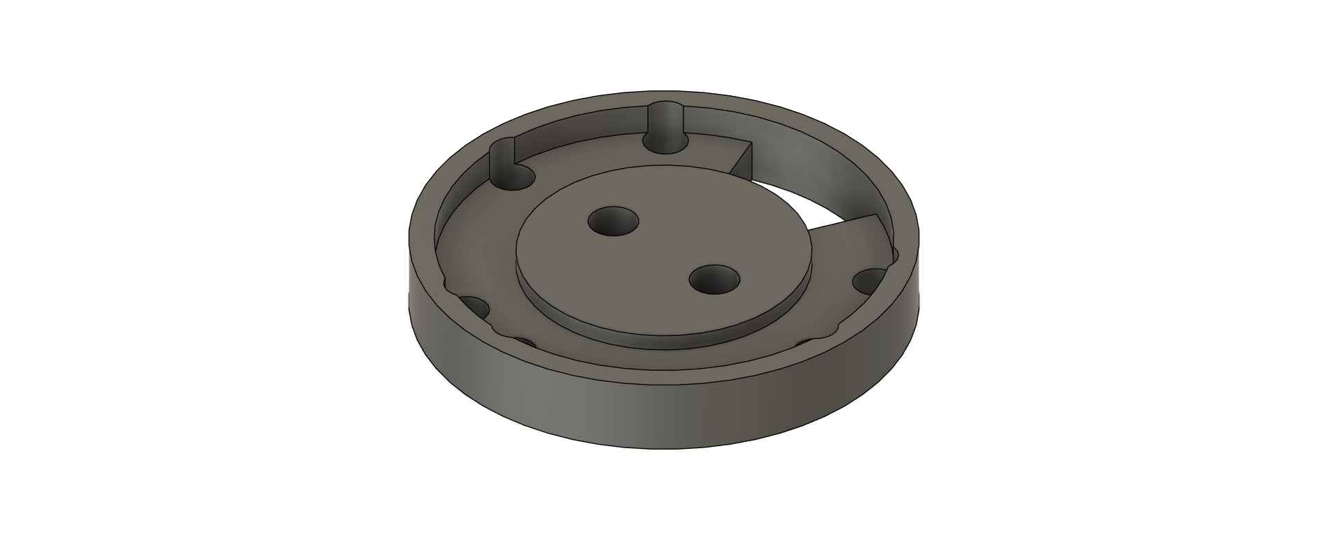
The Neopixel ring holder was 3D printed using a Prusa MK4S Plus with generic PLA settings. The following pictures demonstrate how the Neopixel ring fits securely into the holder.
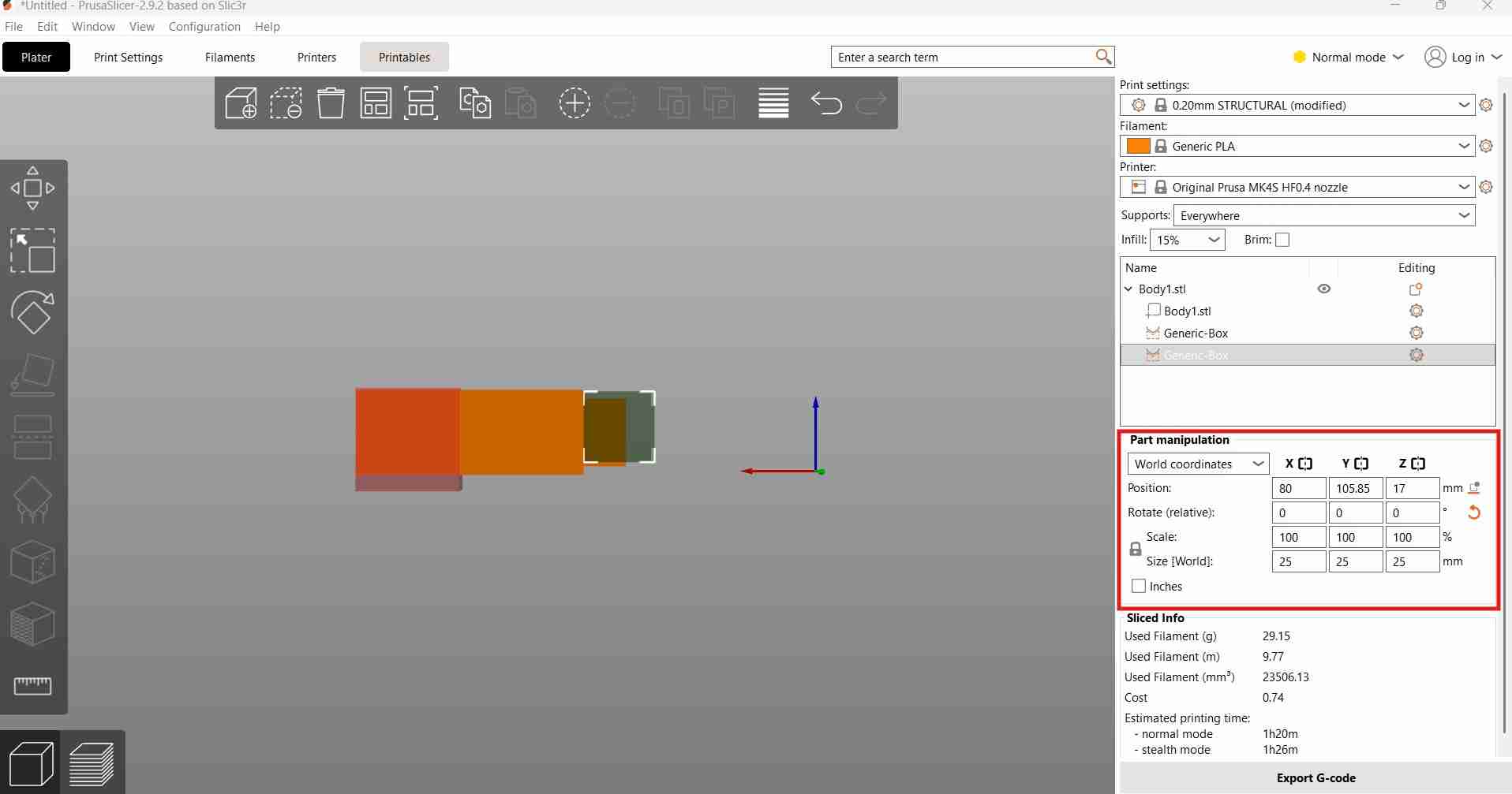
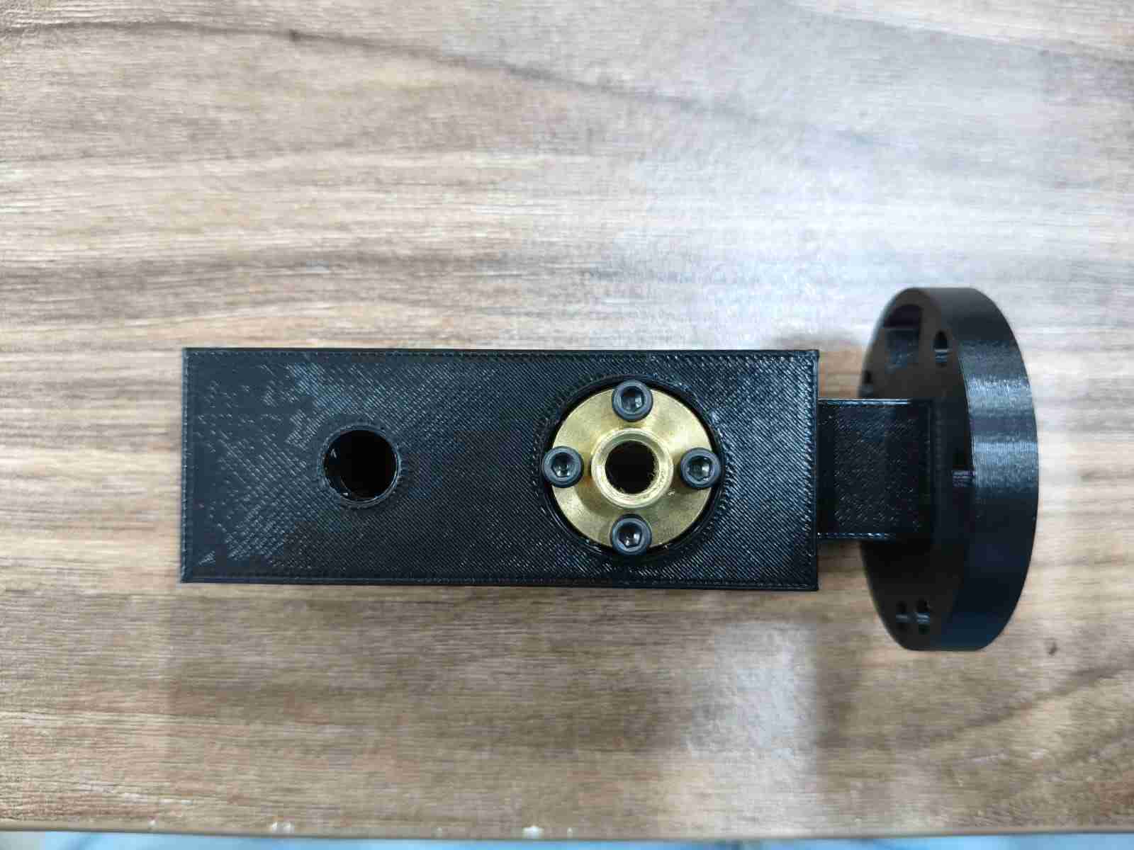
The ring carrier was designed with specific cavities to accommodate the ring holder, a screw nut, and a linear ball bearing. This component is intended to fit M3 x 25 mm screws for secure assembly.
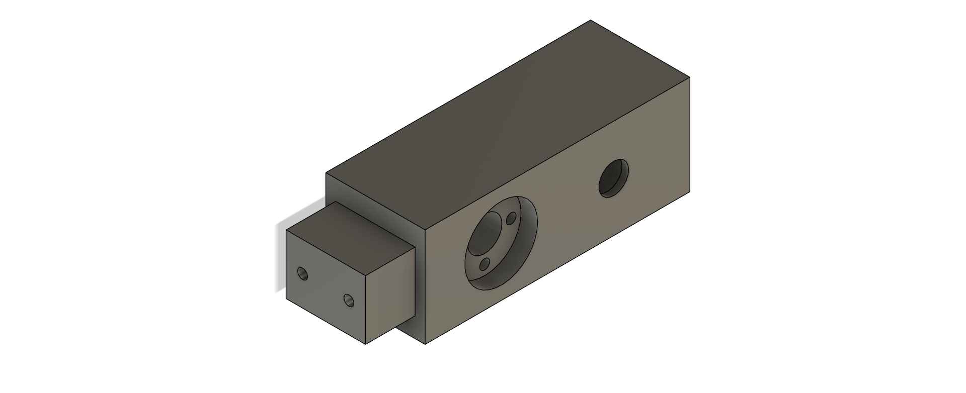
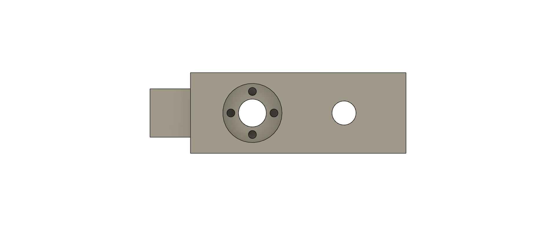
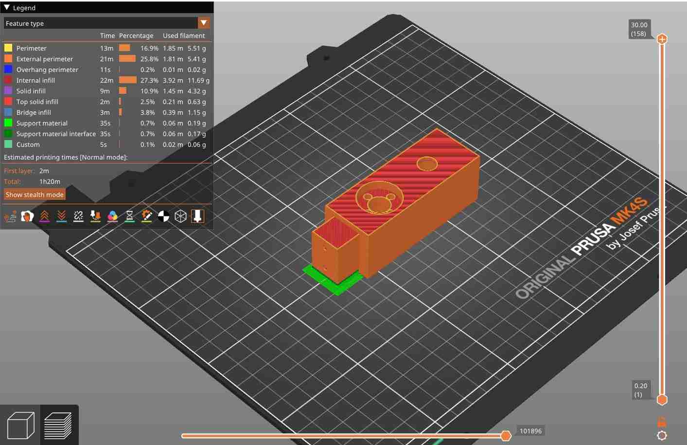
Printing the carrier presented some challenges, as certain sections required support material. The slicer software automatically filled the ball bearing cavity with supports, which made removal difficult once the part was printed.
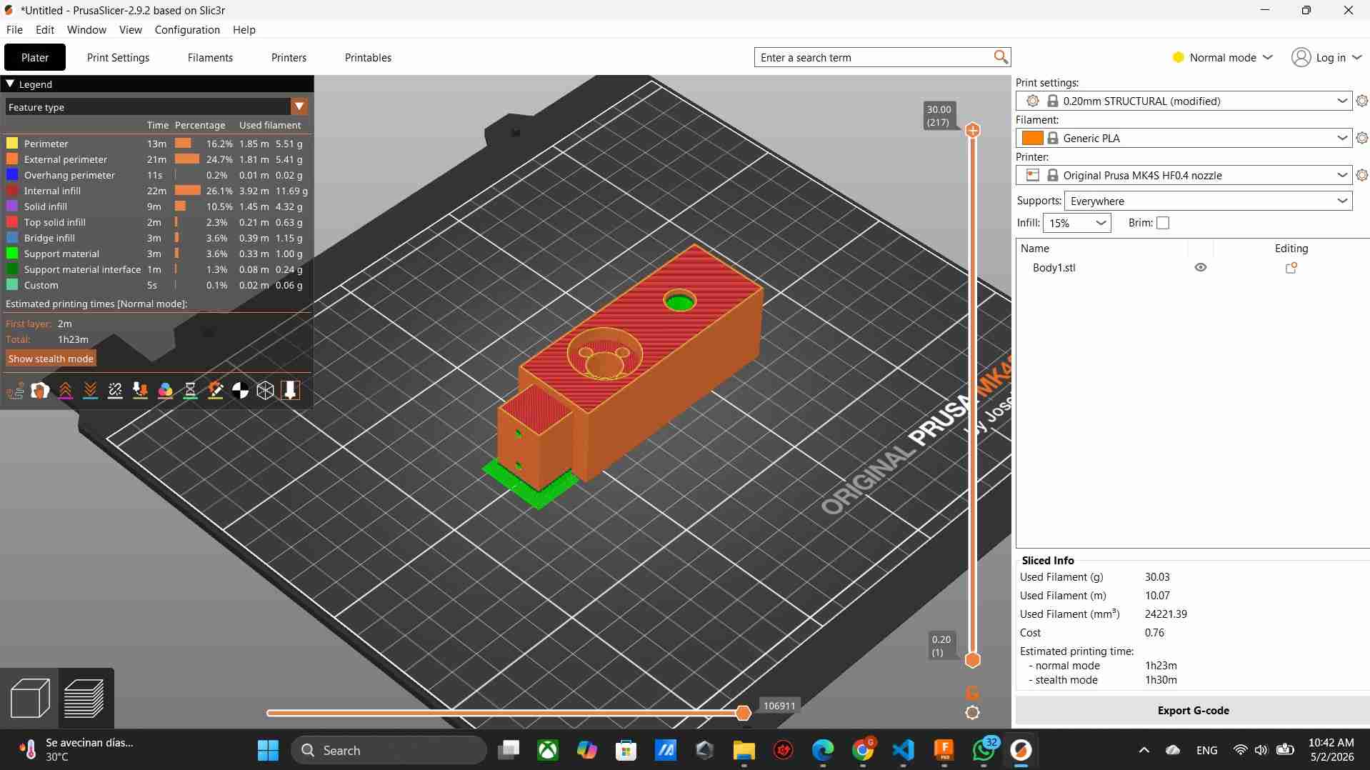
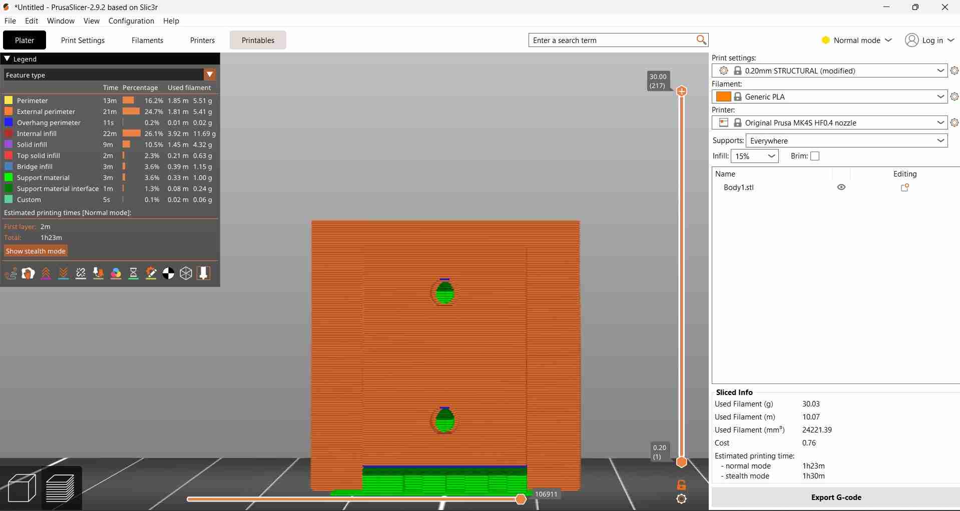
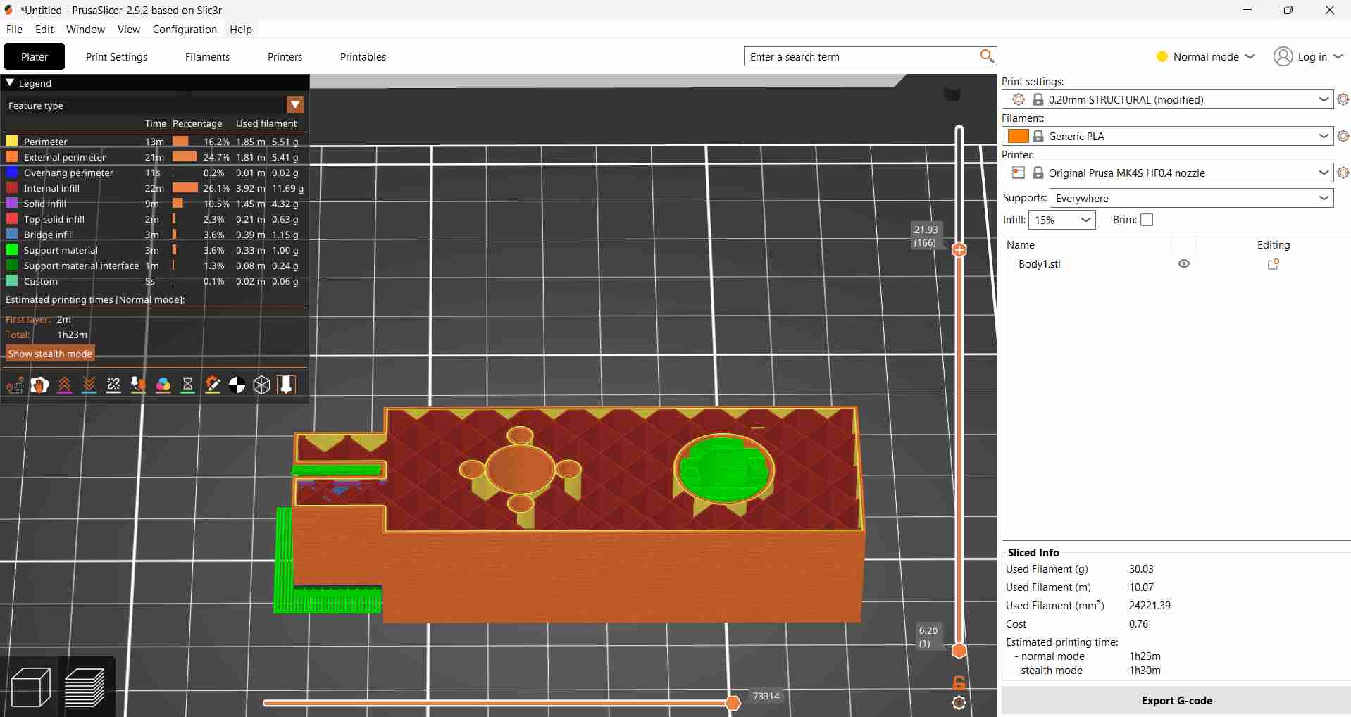
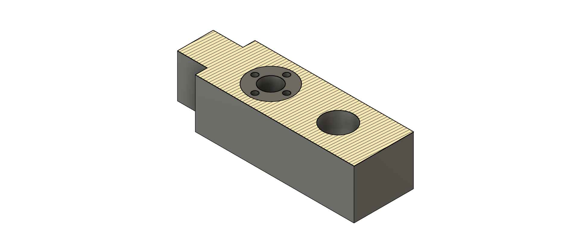
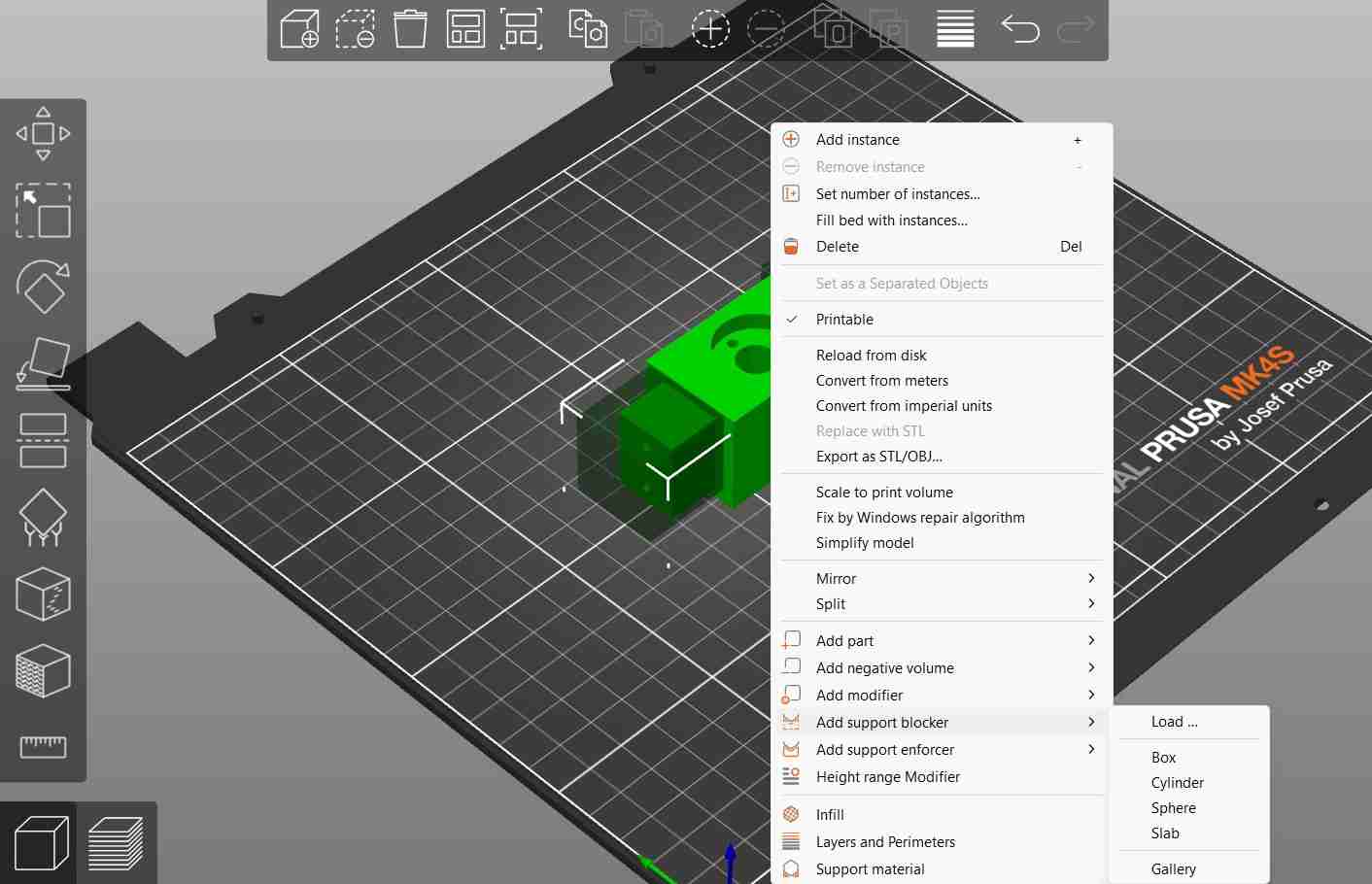
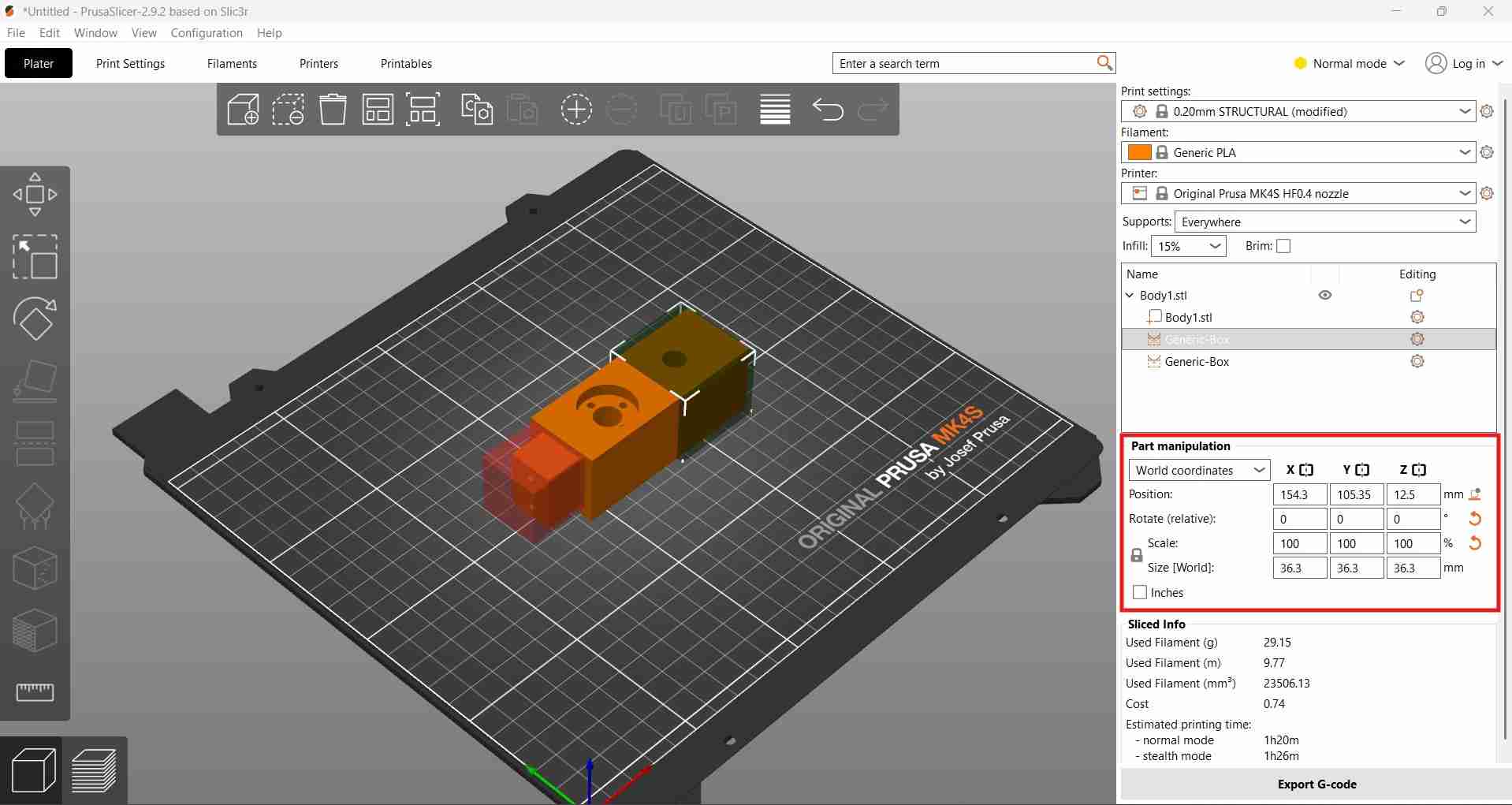
I resolved the support material issue by adding support blockers in the areas where support would be difficult to remove. These blockers, which can be shaped as spheres or cubes, can be sized and positioned as needed to prevent support material from being generated in specific regions of the print.
I also added a pause in the print process to allow for the placement of the ball bearing before its cavity was completely enclosed.
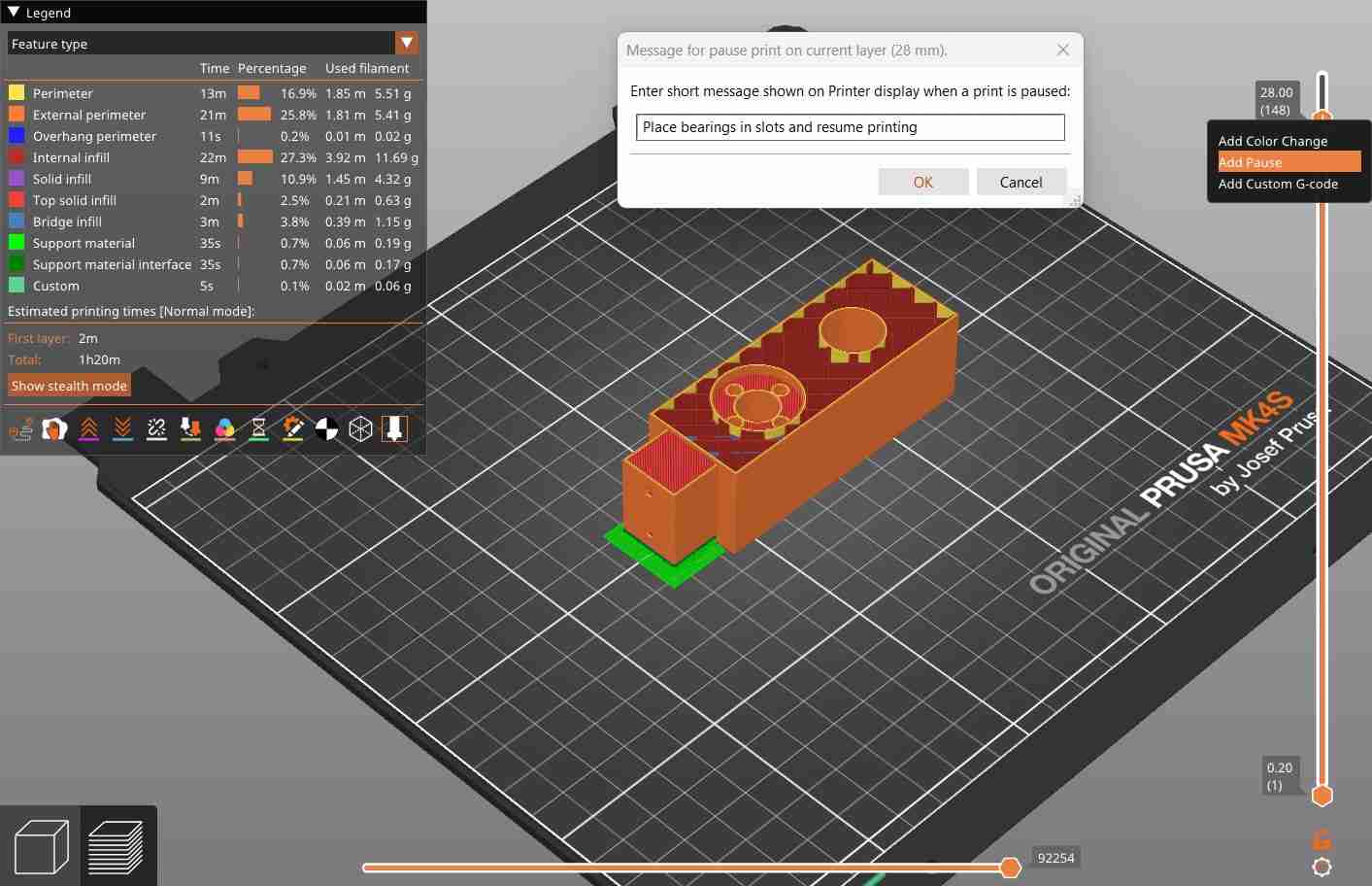
Linear ball bearing placement during the scripted print pause.
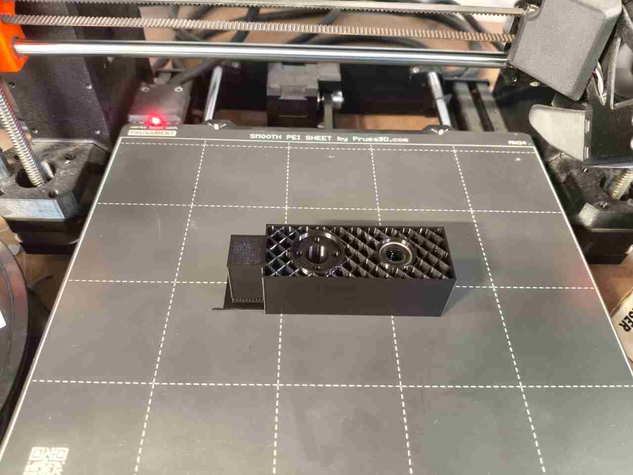
With the carrier already printed, I proceeded to attach the ring-holder and the nut using M3x25 mm screws.
4. Files
Here are the downloadable files for this week:
Codes and CAD files for Week 12Reflection
I was initially excited about developing an Opentrons-style machine, but I am pleased that my team and I were able to successfully adapt and repurpose our project to meet new requirements following our change in direction. My contributions extended beyond designing the end effectors for both machines. I also assisted with electronics design by recommending alternative components, such as linear 3.3-volt regulators and a buck converter, to improve power delivery to our end effector. For more details on these aspects, please visit the personal site of my teammate, Alex Reyes.