Week 10: Output Devices
This week we reviewed different electronic output devices, which are common in consumer electronics and retail products. As an individual assignment, I added an output device to a microcontroller board I designed and programmed it to do something. The power consumption of different output devices was measured as part of the group assignment. Click here to check on this week's group assignment page.
Work log
Completed tasks
- Designed a microcontroller board for handling output devices.
- Designed a breakout board for an H-bridge chosen for my final project.
- Integrated both the breakout and microcontroller boards for controlling an output device.
1.What is an output device?
In electronics, an output device is a component that converts electrical energy into a form that can effectuate a change in the environment or be perceived by humans or other systems. Examples of output devices include LEDs, LCDs, buzzers, speakers, and actuators, such as DC, servo, or stepper motors. When selecting an output device, it is paramount to consider factors such as power consumption, brightness, size, and the type of signal it needs to respond to.
2.Which output device I worked with for this assignment?
As I mentioned on my final project page, I am working on a revised version of a mobile robot with transforming wheel legs that I developed during my master's degree studies. Similar to the previous version, I plan for each wheel-leg to be actuated by an individual motor. For the variable geometry, I intend to maintain my current actuation scheme, which utilizes a micrometal gear motor paired with a metallic worm drive.
My current system comprises eight micrometal gear motors. I opted to control each motor using a commercial DRV8871 board, as my project's initial goal was to measure the current for each motor during operational cycles. I planned to use these current measurements to develop strategies for gait and wheel transformation. Since each DRV8871 needed to be powered individually, I was able to measure the current for each motor accordingly.
Each DRV8871 was controlled by a Teensy 4.1 development board. As I mentioned during Week 4 , this board costs around $50, which represents a serious blow to a project budget whenever one of those boards is damaged, as has already happened during the development of my robot. Although the processing power of the Teensy 4.1 enables complex control algorithms, my project's objectives do not require such processing power for RTK navigation. For this iteration of the robot, I have decided to replace the Teensy 4.1 board with a Xiao ESP32C6 board. This new setup will be used in conjunction with four Attiny 1616 MCU boards. For this week's assignment, I designed and tested my own versions of an Attiny 1616 breakout board and DRV8871 drivers.
3.What is a micrometal gear motor?
To understand what a micrometal DC motor is, we should first explore its broader category, the DC motor. A DC motor is a device that operates on direct current (DC) and converts electrical energy into rotational motion. The most common type of DC motor is the brushed DC motor. In these devices, current flows through coils in the rotor, creating interactions between magnetic fields that cause the shaft to rotate. Brushes and a commutator work together to ensure that the torque remains correctly directed as the rotor turns.
In a DC motor, applied voltage mainly influences the motor’s no-load or steady-state speed, while armature current is directly related to torque. Increasing the applied voltage generally allows the motor to reach a higher speed because the motor accelerates until the generated back EMF nearly balances the supply voltage. As the motor spins, it produces a back EMF that opposes the applied voltage, and this back EMF increases with rotational speed. At steady state, the applied voltage is approximately equal to the back EMF plus the voltage drop across the motor winding resistance and other losses.
Current flows through the windings, creating a magnetic field in the rotor, which in turn produces torque. In a brushed DC motor, torque is approximately proportional to current. When the motor experiences a heavier load, it draws more current to generate the necessary torque. On the other hand, when the motor spins freely with little load, it needs less torque and, as a result, uses less current. As the load increases, the motor may slow down slightly, which reduces the back EMF. This reduction permits more current to flow, and the additional current results in increased torque.
While a motor can spin very fast, its output is often connected to a gearbox that reduces speed while increasing torque. The speed of a motor refers to how quickly it can rotate, whereas torque indicates how forcefully it can twist. A low-torque motor might rotate freely in the air, but when a load is attached, it can slow down, stall, or overheat. Torque is essential for real-world applications that involve lifting, accelerating from a standstill, or maintaining a position against gravity. Gearmotors address the need for increased torque by using gears to reduce speed and increase torque, thereby providing mechanisms with more usable force.
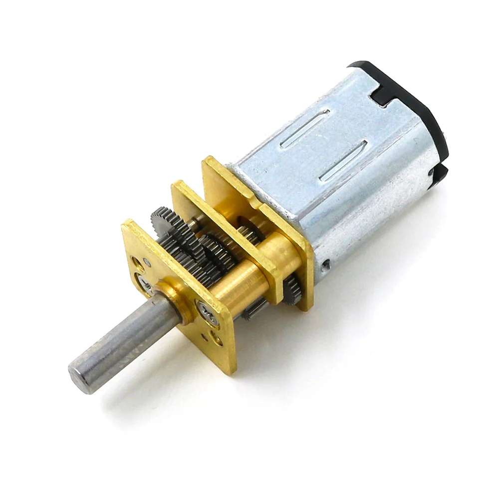
A micrometal gear motor is composed of two main components: a small brushed DC motor and a metal gearbox. The key parts of a micrometal gear motor include the following:
- Motor terminals: Two electrical connections where direct current (DC) voltage is applied. Power enters through one terminal and exits through the other. Reversing the polarity causes the motor to change direction. This is the general principle behind powering brushed DC motors.
- Brushes: Stationary components that make contact with the spinning commutator. Their function is to conduct current from the external circuit to the rotating part of the motor. In small brushed motors, the materials used for brushes typically include precious metals or carbon, depending on the specific motor design.
- Commutator: A segmented metal ring connected to the rotor. As the rotor rotates, the brushes make contact with different segments of the commutator, which changes which coil receives power at any given moment. This mechanical switching mechanism ensures that the motor continues to turn in the same direction rather than stopping after completing part of a turn.
- Rotor: Rotating inner part of the motor. It contains wire windings. When current flows through those windings, they create a magnetic field that interacts with the stator magnets to produce torque.
- Stator magnets: Permanent magnets fixed to the motor housing. They do not rotate, instead providing the magnetic field that the energized rotor pushes against.
- Motor shaft: The rotating shaft that transfers mechanical energy from the motor to other components.
- Gearbox: Gearbox: The front section contains multiple small gears. Its purpose is to reduce speed and increase torque. A higher gear ratio results in lower output speed and higher torque. As suggested by their name, the gears in a micrometal gear motor are made of metal.
- Gear train: Stages of gears inside a gear box. Each stage trades a bit of speed for more turning force. By the time the motion reached the front shaft, it was much slower but much stronger than the raw motor output.
- Output shaft: The front shaft that extends from the gearbox. It is the point where the motor's mechanical output can be connected to other components, such as wheels or levers.
- Bearings/ bushings and housing: These components support the rotating shaft and keep everything aligned. The housing holds the motor and gearbox together.
When selecting a motor, it is crucial to ensure that the torque it provides under normal operating conditions does not surpass the stall torque. "Stall" refers to the situation where the motor is overloaded but the shaft remains stationary. This condition results in two critical values: stall current, which is the current drawn by the motor when it is energized but not rotating, and stall torque, the highest torque the motor can generate when it is at a standstill. Both stall torque and stall current should be avoided, as stall represents one of the most demanding situations a motor can encounter, primarily due to the risk of overheating. When the shaft is not in motion, the current increases, converting electrical power into heat within the windings, resulting in minimal or no cooling benefits from rotation. Overheating can damage the components of a micrometal gear motor and its driver circuit.
The micrometal gear motors I used for this assignment were rated for a voltage of 12 V, a speed of 100 rpm, a no-load current of 0.03 amperes, and a current of 0.09 amperes at a rated load. They also have a stall current of 0.7 amperes and a stall torque of 15.5 kgf cm.
4. What is a motor driver?
A motor driver is an electronic circuit situated between a microcontroller and a motor. It allows the low-power control signals from the microcontroller to safely manage the significantly higher power required by the motor. Motors need enough current, protection from electrical noise and voltage spikes, a way to change direction, and a higher voltage than what the microcontroller pins can give them. A motor driver acts like a power amplifier and switch system for the motor; in turn, the microcontroller dictates when to turn on, turn off, go forward, go backward, and speed. Even though a microcontroller can provide a 5-volt signal sufficient to power a small DC motor, a motor driver is still necessary. A motor is an inductive load; inductors resist changes in current. When current through a motor winding changes suddenly, the motor can generate voltage spikes. Voltage spikes can reset the microcontroller, create noise, and damage electronics if not controlled properly.
To reverse a brushed DC motor, the polarity across its terminals must be changed. This requires a specific switching arrangement, typically an H-bridge. An H-bridge is a circuit configuration that enables a DC motor to be driven in both directions. It is named an H-bridge because its basic schematic resembles the letter H. The motor is depicted as the horizontal bar in the center, with four switches (commonly transistors or MOSFETs) arranged around it. A transistor is a component that allows a small control signal to manage a larger current flow. In motor driver applications, transistors function as switches rather than as linear amplifiers. When a transistor is in the ON state, current can flow; in the OFF state, current is blocked.
A bipolar junction transistor, or BJT, has three terminals: base, collector, and emitter. A small current entering the base allows a larger current to flow from the collector to the emitter. A base signal can be interpreted as the command that opens the switch. A base signal can be interpreted as the command that opens the switch. Currently, BJTs are less common in modern motor drivers due to their power waste when compared to MOSFETs, which are more efficient and generate less heat, making them preferable for applications requiring high efficiency and performance.
A MOSFET, or metal-oxide-semiconductor field-effect transistor, also has three main terminals: gate, drain, and source. The gate is different from the BJT base because ideally it does not need continuous current in the same way. It is mainly voltage-controlled. If the voltage between gate and source is high enough, the MOSFET turns on and creates a low-resistance path between drain and source. This voltage-oriented control results in H-bridges that are fast-switching, efficient, and generate low heat when properly driven.
DRV8871 Motor Driver
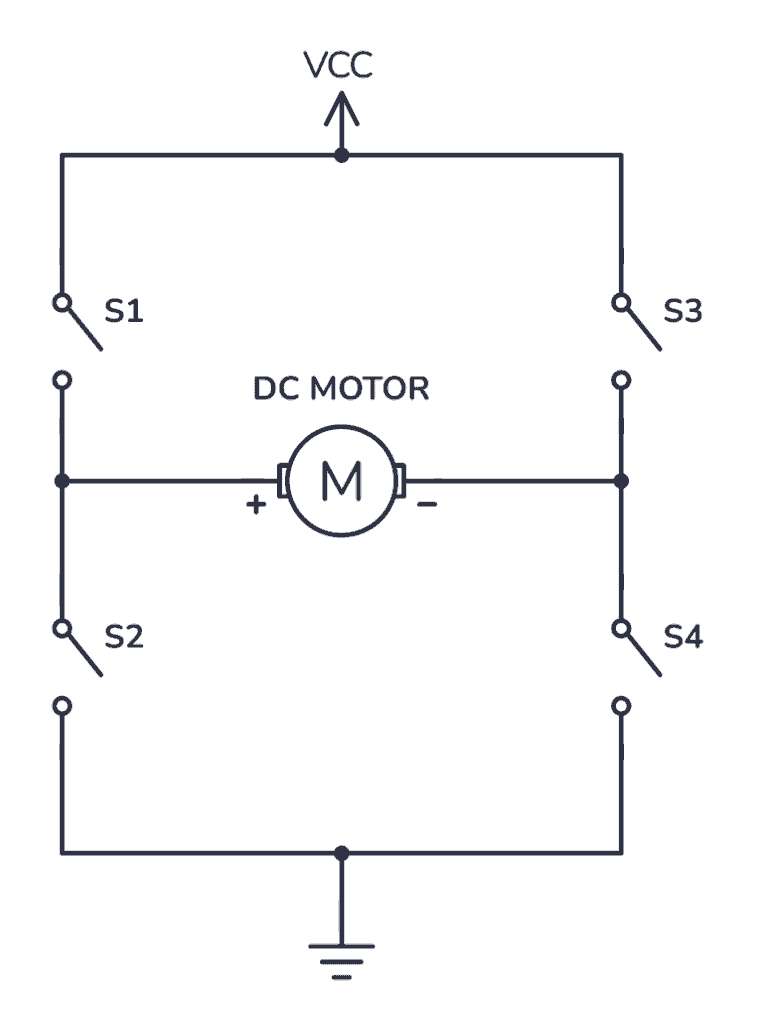
To spin the motor in one direction, the microcontroller must activate switches S1 and S4, creating a current path that flows from VCC through S1, through the motor, and then through S4 to GND. To reverse the motor's direction, the microcontroller must activate switches S2 and S3, establishing a current path from VCC through S2, through the motor, and then through S3 to GND. This switching of current paths results in a voltage reversal across the motor, changing its spin direction. The switches on the same side must not be activated simultaneously; for example, activating S1 and S3 together or S2 and S4 together would create a direct short to ground, resulting in a shoot-through condition. A proper motor driver chip is essential for preventing or managing this situation safely.
The H-bridge selected for this assignment is the DRV8871, which is a single-channel H-bridge motor driver manufactured by Texas Instruments. This driver is primarily designed for controlling a single brushed DC motor or one winding of a stepper motor; however, I do not recommend it as the first choice for stepper motor applications. When operating a DC motor, the DRV8871 requires only two Pulse Width Modulated (PWM) signals to manage speed and direction (forward or backward) as well as braking or coasting. The following table contains the main specs from the DRV8871:
| Feature | Attribute |
|---|---|
| Motor type | Brushed DC motor or one winding of a stepper motor |
| Motor supply voltage, VM | 6.5 V to 45 V |
| Peak current | 3.6 A |
| Logic control | 2 inputs: IN1 and IN2 |
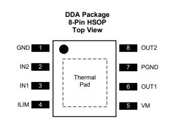
| Package | 8-pin HSOP with thermal pad |
| Protection | Undervoltage, overcurrent, thermal shutdown |
| Current limiting | Yes, set with external RILIM resistor |
The following image shows the pinout of the DRV8871:
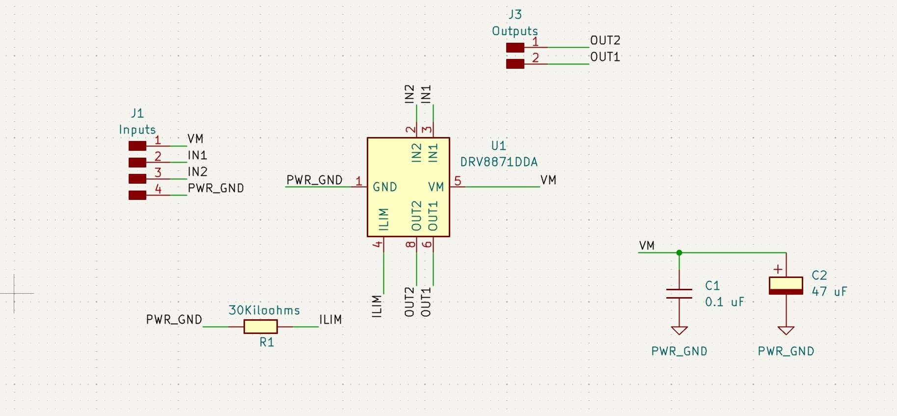
The schematic for the DRV8871 is shown below:
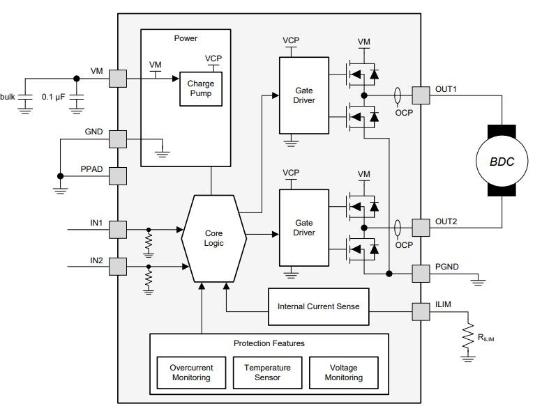
The DRV does not need separate direction and PWM pins; instead, it uses IN1 and IN2 directly:
| IN1 | IN2 | Motor behavior |
|---|---|---|
| 0 | 0 | Coast/ sleep |
| 1 | 0 | Motor running (forward) |
| 0 | 1 | Motor running (backward) |
| 1 | 1 | Brake |
One distinctive feature from the DRV8871 is its current regulation. Unlike other drivers, such as the L298N and TB6612FNG, the DRV8871 can limit motor current by using an external resistor on the ILIM pin. This is useful because DC motors can draw a high current when starting, stalled, or heavily loaded. To fulfill its intended purpose, a RILIM resistor is connected to the ILIM pin of the DRV8871 to set the driver's current limit.
The relationship is approximately the following:
I_LIMIT = 64 / R_ILIM
- I_LIMIT= Limiting current in amps
- R_ILIM= Value of the ILIM pin resistor in kilo-ohms
So, for example:
| RILIM resistor | Approx. current limit |
|---|---|
| 15 kilo-ohms | 4.27 A |
| 18 kilo-ohms | 3.56 A |
| 22 kilo-ohms | 2.91 A |
| 33 kilo-ohms | 1.94 A |
| 47 kilo-ohms | 1.36 A |
| 68 kilo-ohms | 0.94 A |
| 100 kilo-ohms | 0.64 A |
A lower resistor value delivers a higher current limit, while a higher resistor value equals a lower current limit.
DRV8871 drivers are often purchased in the breakout board form factor, exposing their inputs and outputs via pin headers and terminal blocks. These breakout boards also contain the necessary capacitors for smooth motor operation.
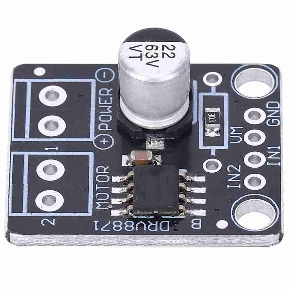
The simplicity of the breakout boards for this driver makes their fabrication using rapid prototyping machines straightforward. Therefore, I chose to design a breakout board for a single motor using the DRV8871. I decided to omit the holes for the terminal blocks, as I intend to connect these drivers to the microcontrollers of my final project via cleaner connections, like pin headers. I included an electrolytic bulk capacitor to provide the big short bursts of current the motor wants at startup or during load changes. I also added a ceramic capacitor to absorb sudden voltage spikes and switching noise created when the H-bridge turns on and off. To limit the current consumption at 2 A, I used a 30-kilohm resistor on the ILIM pin. This current value is suitable for my motors, as their stall current is equivalent to 0.7 A.
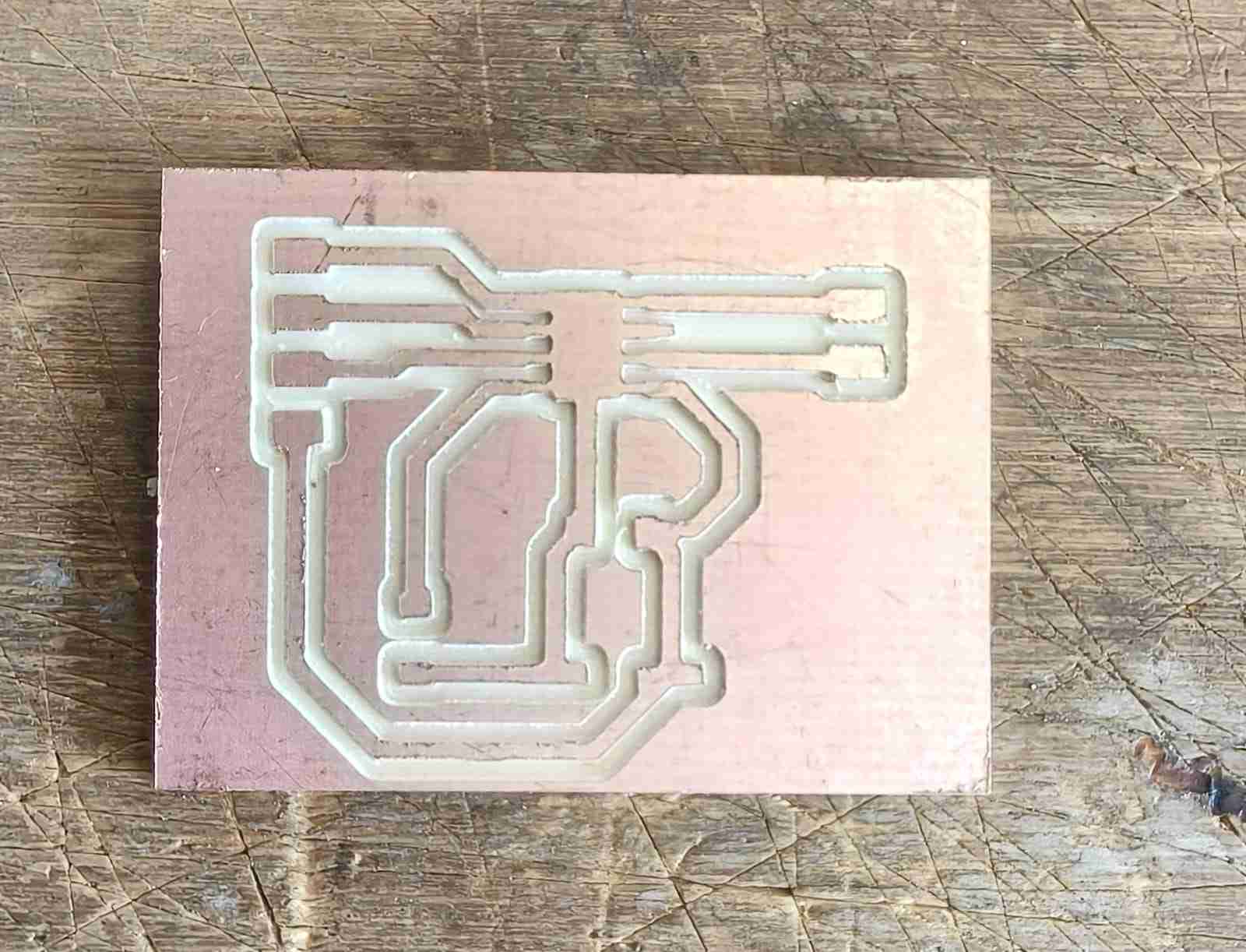
The PCB layout features a track width of 0.8 mm for all connections, which is adequate for managing 2A currents. As mentioned earlier, this width is well below the stall current threshold of the motors I intend to use. Since the schematic does not include any through-hole components, this PCB can be easily produced as a single-layer board, following a manufacturing process similar to the one outlined in the Week 8 assignment .
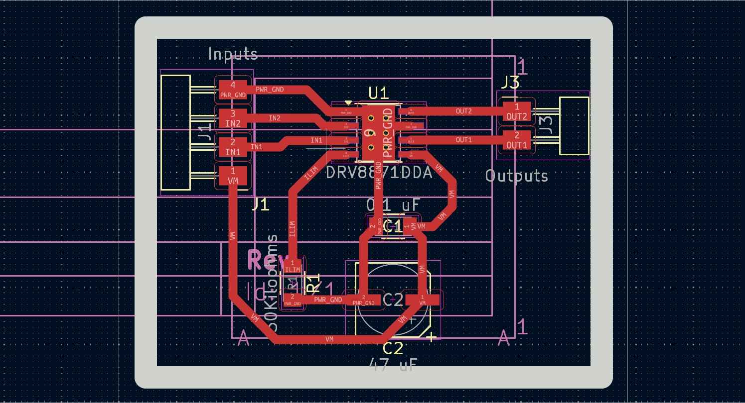
After manufacturing the DRB8871 PCB, I noticed every pin was connected to the GND thermal pad, which would have certainly short-circuited the whole breakout board.
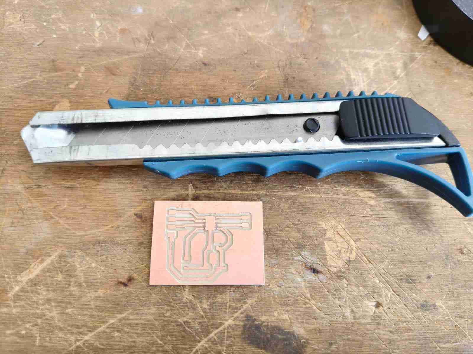
I used a cutter to manually sever the connection between input and output pins to the GND (ground) thermal pad. It did not take long to achieve this result. After I was done with this process, I proceeded to use a multimeter to check if there was continuity between any tracks. Once I confirmed the proper isolation of each track, I moved on to solder the components for this breakout board.
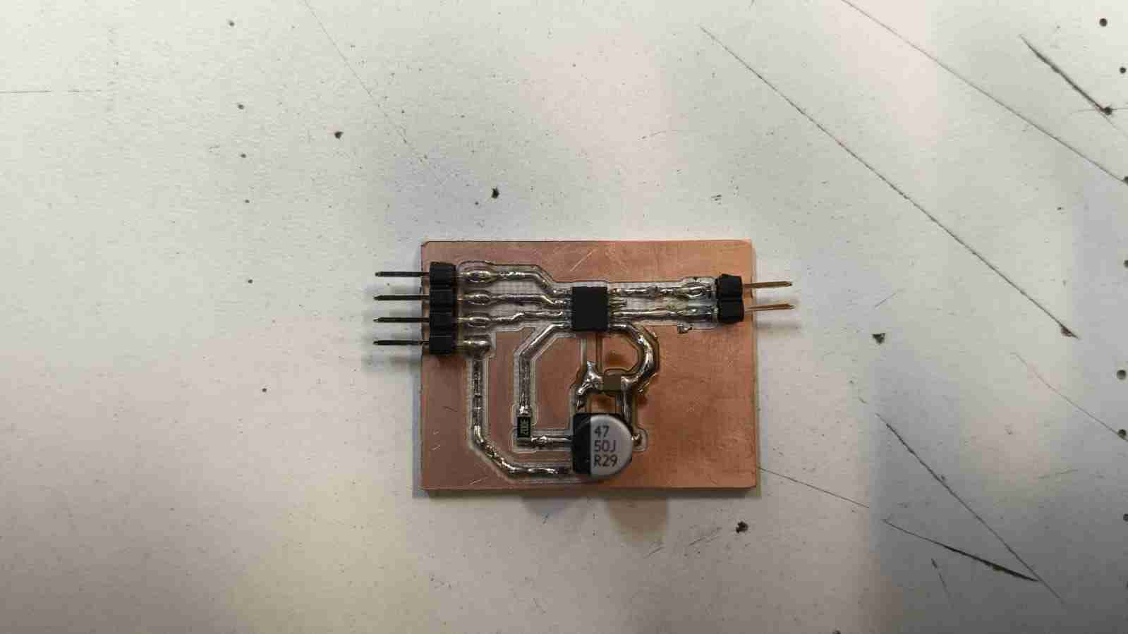
After soldering the components using the techniques outlined in Week 8 and checking with a multimeter to ensure there were no unintended connections between tracks due to soldering errors, the DRV8871 breakout board was finished.
5. Microcontroller Board
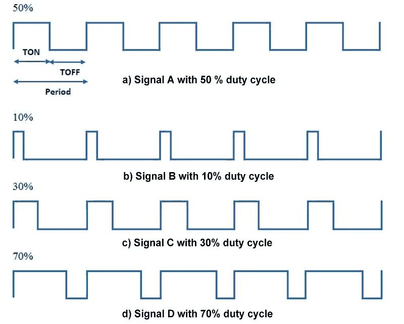
Before delving into the microcontroller used for this assignment, I want to talk about PWM signals. A pulse-width-modulated (PWM) signal is a digital pulse train characterized by a fixed amplitude, a selected frequency, and a variable duty cycle. This type of signal can be understood as one that quickly alternates between fully ON and fully OFF states, controlling power by adjusting the duration it remains ON during each cycle.
- Amplitude: The maximum value of the PWM signal. For example, 0V to 5V from a microcontroller, or 0V to 16 V at a motor terminal after a driver stage.
- Frequency: The number of PWM cycles per second. It determines how fast the signal switches between ON and OFF states. Frequency = 1/Period
- Duty cycle: The percentage of time the PWM signal is in the ON state during each cycle. It is calculated as (ON time / Total time) * 100%. This parameter controls the average power delivered to the load.
PWM signals are widely used to control motor speed. By generating a series of rectangular pulses, these signals can regulate the duration for which the gates of an H-bridge remain open, thereby controlling how long the motor is active or spinning.
A PWM (Pulse Width Modulation) signal delivers the full supply voltage to the motor in brief, repeated pulses. The motor primarily responds to the average effect of these pulses, rather than detecting PWM signals in the same manner as a voltmeter. As an electromechanical inductive load, the motor tends to react mostly to the average effect of the pulses, especially when the PWM frequency is sufficiently high. For instance, a motor connected to a driver with a 16 V battery can safely power a 12 V DC motor using PWM; however, the duty cycle must be low enough to produce an average voltage of about 12 V from the 16 V supply, which can be achieved with a 75% duty cycle.
As I mentioned earlier, I am redesigning the electronics package for my robot. The Raspberry Pi Pico 2 will serve as the foundation for motor control in my project. To enhance its capabilities, I plan to incorporate Attiny 1616 microcontrollers to manage additional sensors and improve overall processing efficiency. The Attiny 1616 includes features such as timers, ADC, USART, SPI, I2C, and the Event System, which allows peripherals to trigger one another with minimal or no CPU involvement. It also offers options for flexible PWM management. This microcontroller enables updates to the duty cycle without glitches, and PWM configuration can be customized for switching behavior or timing symmetry.
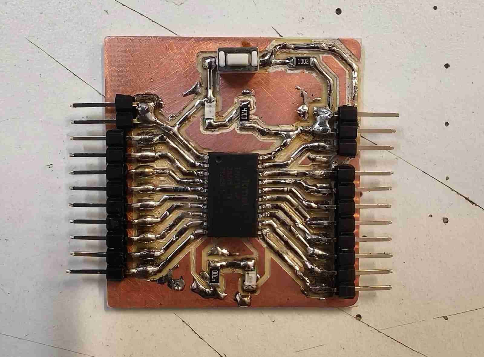
The Attiny features 10 PWM (pulse-width modulation) output pins, making it a suitable option as an additional motor controller when connected to the Raspberry Pi Pico 2 via I2C (Inter-Integrated Circuit). Typically, the Attiny 1616 is available as a 20-pin integrated circuit without a breakout board, prompting me to design a PCB to interface this microcontroller with other programmable components. The KiCAD schematic for the PCB incorporates a push button and an LED as peripherals, with an additional LED connected in parallel to the microcontroller's power source. All pins of the microcontroller are accessible through pin headers.
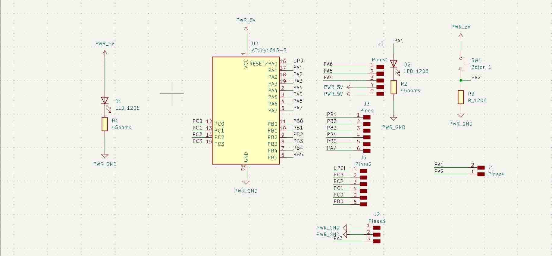
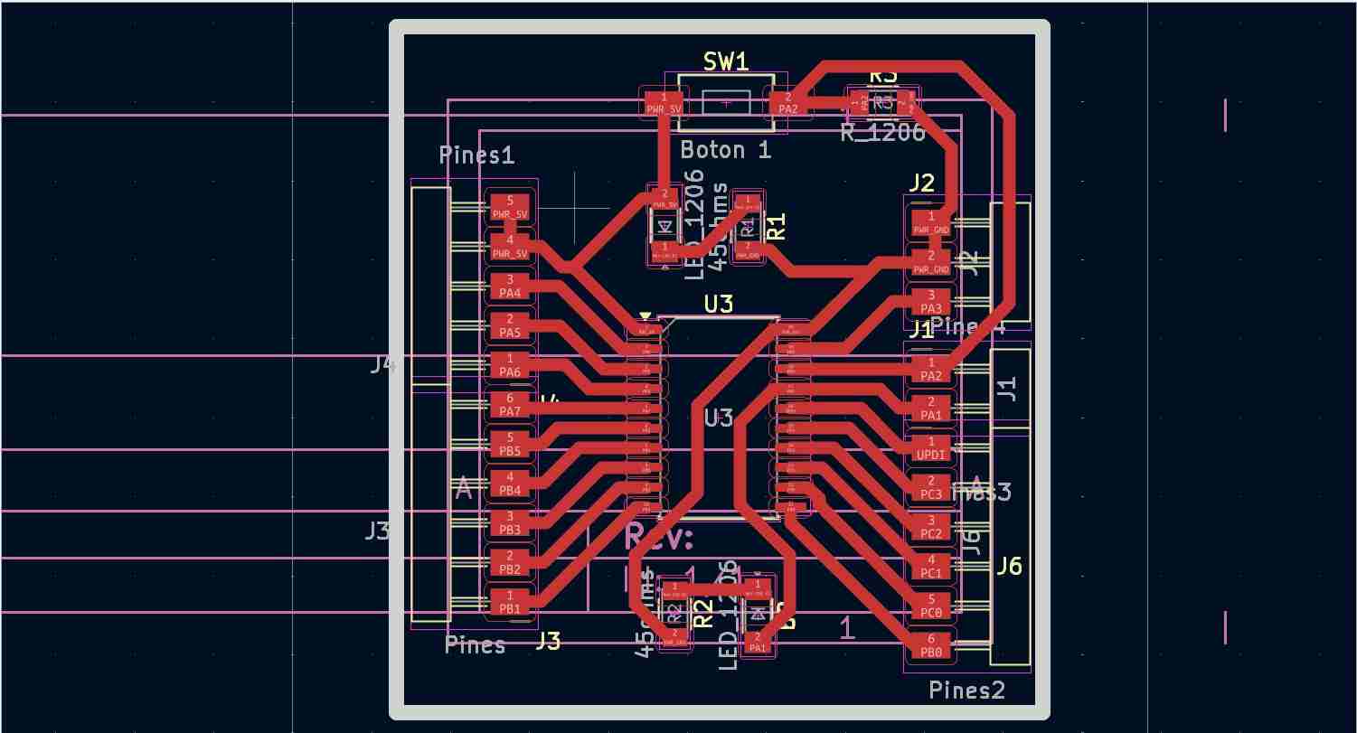
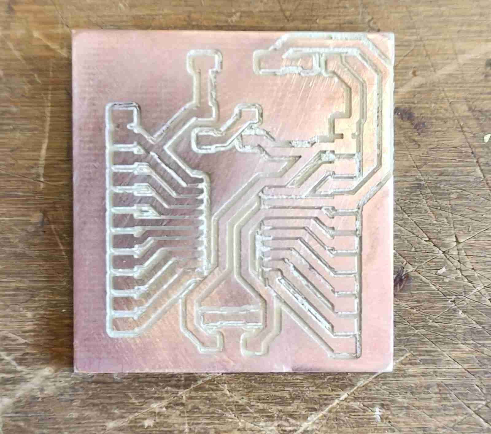
For the PCB layout, the track width is set at 0.8 mm, and all components are placed on the same layer, resulting in a single-layer PCB. This board was designed with consideration of the previously referenced manufacturing techniques.
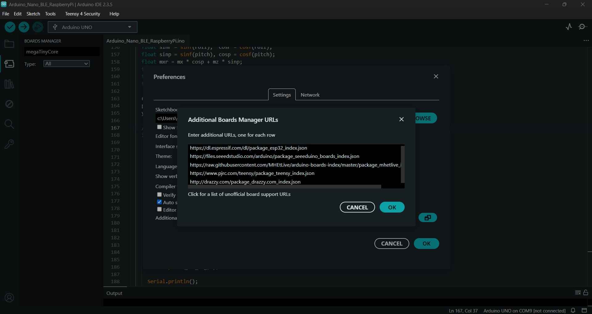
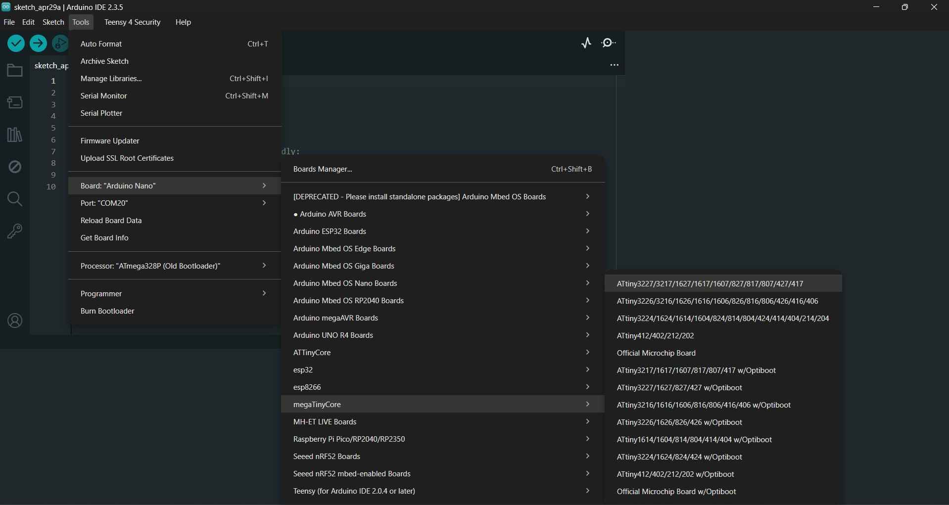
The Attiny board lacks a USART (Universal Asynchronous Receiver-Transmitter) interface, which prevents it from being programmed in the typical manner. Consequently, alternative methods are necessary, such as using an Arduino Nano configured as a programmer. To establish this setup, we must first install the megaTinyCore board library by adding the relevant link in the preferences tab of the Arduino IDE. The link is http://drazzy.com/package_drazzy.com_index.json
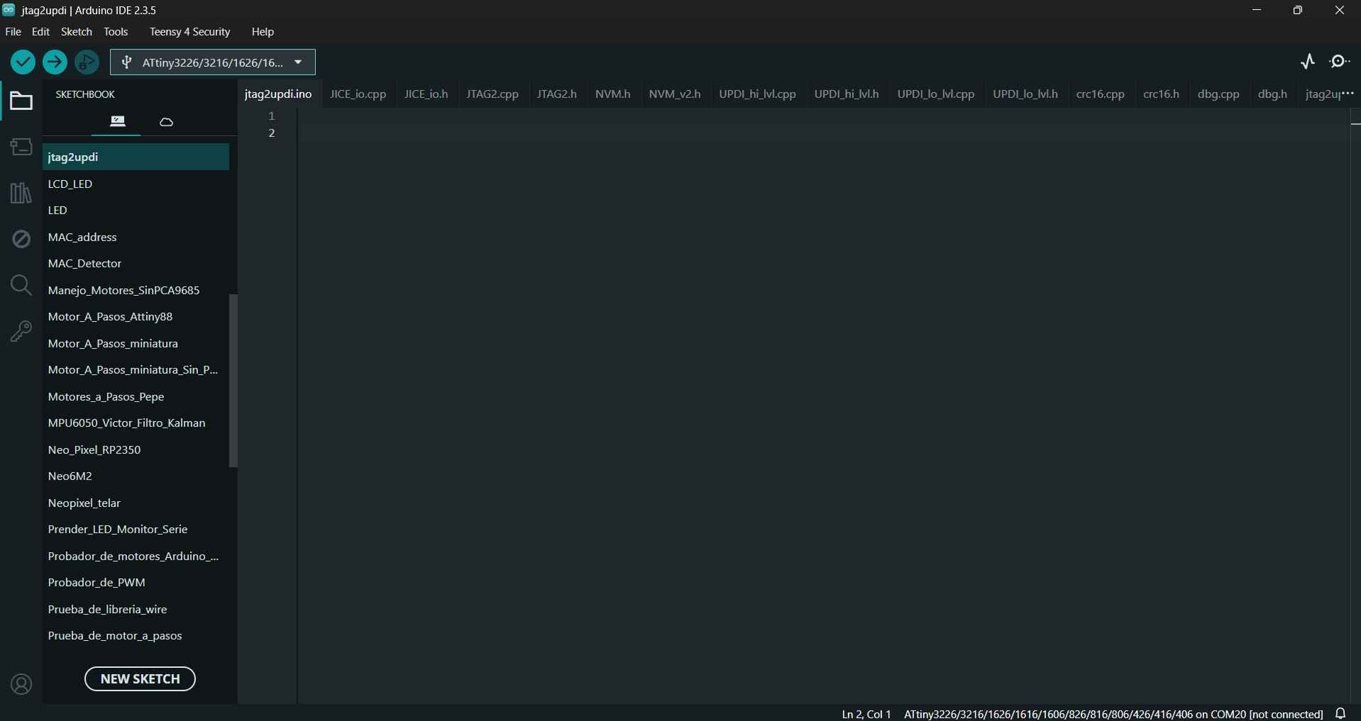
After downloading the aforementioned library, we need to flash the jtag2updi sketch onto our Arduino Nano board, which can be downloaded from here in case of relevant updates, while the current version is included in the files for this week. When opened, the file will display multiple tabs, but the first tab will not show any code to the user. This is not a problem, as the other tabs contain the required code.
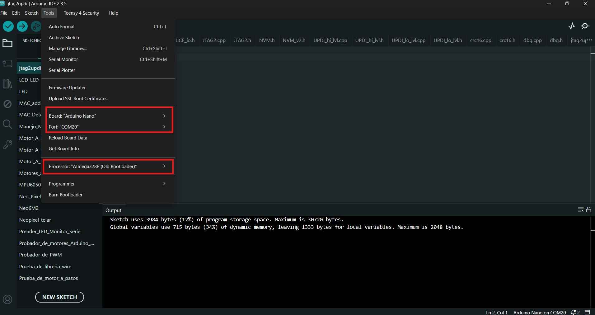
The jtag2updi sketch is uploaded to the Arduino Nano board like any other program. However, in my case, I needed to select the Atmega328P (Old Bootloader) option in the "Programming" field to successfully flash the code.
Before using our new programmer, we need to connect a capacitor between the VCC and GND terminals of the Arduino board. This step is necessary to prevent unwanted restarts when uploading code to our Attiny board.
| 22 uF Electrolytic capacitor | Arduino Nano |
|---|---|
| Positive terminal | VCC |
| Negative terminal | GND |
With the capacitor added, we now need to include a 4.7 kilo-ohm resistor between the Arduino Nano board and the Attiny. The table below outlines the necessary connections for programming our microcontroller.
| Arduino Nano | Attiny1616 |
|---|---|
| D6(4.7 kilo-ohms) | UPDI |
| 5V | VCC |
| GND | GND |
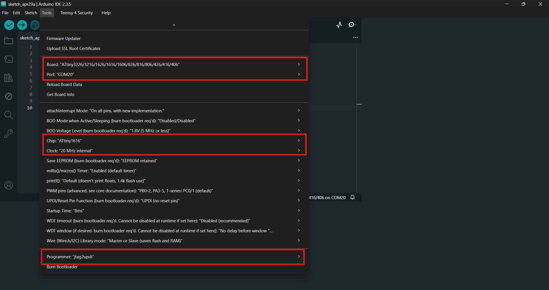
After the hardware is set and ready, we can now open a new Arduino IDE tab and select the Attiny board and its corresponding parameters to upload a code from our programmer to our Attiny PCB.
I initially tested the manufactured PCBs with a simple code to verify that the driver could rotate a 12 V motor in both forward and backward directions. The next section presents the code uploaded to the Attiny board using the Arduino programmer. Since I was unfamiliar with the Attiny 1616 microcontroller, I sought assistance from ChatGPT to help write the code. I provided the following prompt: "I need code that controls two PWM outputs on an Attiny1616 to drive a motor using a DRV8871."
            const int IN1 = PIN_PA1;
            const int IN2 = PIN_PA2;

            void setup() {
            pinMode(IN1, OUTPUT);
            pinMode(IN2, OUTPUT);
            }

            void loop() {
            // Forward-Half Throttle
            analogWrite(IN1, 128);
            digitalWrite(IN2, LOW);
            delay(3000);

            // STOP
            digitalWrite(IN1, LOW);
            digitalWrite(IN2, LOW);
            delay(1000);

            // Backwards-Half Throttle
            digitalWrite(IN1, LOW);
            analogWrite(IN2, 128);
            delay(3000);

            // STOP
            digitalWrite(IN1, LOW);
            digitalWrite(IN2, LOW);
            delay(1000);
            }
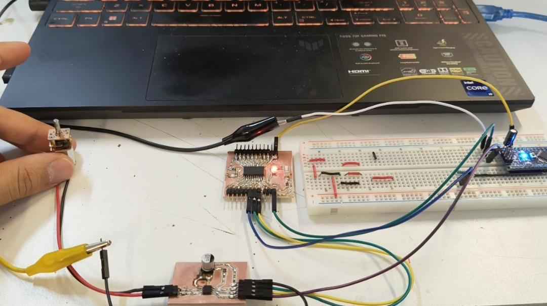
After confirming that the Attiny board could effectively control the motor through the DRV8871 board, I chose to let the circuit operate under supervision. I monitored the setup for 10 minutes, during which the circuit did not show any signs of failure. Given this positive outcome, I decided to add a UART adapter to facilitate sending commands to the Attiny board via a serial port. The commands were designed to control the motor's speed and direction and to start or stop its operation. Once again, this code was made with the assistance of ChatGPT; this time, the prompt was the following: "Now I need to send commands to my Attiny through an external USART adapter; I want to control speed and direction."
            const uint8_t IN1 = PIN_PA1;
            const uint8_t IN2 = PIN_PA2;

            uint8_t speedValue = 180;  // 0 to 255

            void motorStop() {
            digitalWrite(IN1, LOW);
            digitalWrite(IN2, LOW);
            }

            void motorForward(uint8_t pwm) {
            analogWrite(IN1, pwm);
            digitalWrite(IN2, LOW);
            }

            void motorReverse(uint8_t pwm) {
            digitalWrite(IN1, LOW);
            analogWrite(IN2, pwm);
            }

            void setup() {
            pinMode(IN1, OUTPUT);
            pinMode(IN2, OUTPUT);

            motorStop();

            Serial.begin(9600);
            delay(100);

            Serial.println("Ready. F, R, S, 0-9 for speed");
            }

            void loop() {
            if (Serial.available() > 0) {
                char cmd = Serial.read();

                if (cmd == 'F' || cmd == 'f') {
                motorForward(speedValue);
                Serial.print("Forward, PWM=");
                Serial.println(speedValue);
                }
                else if (cmd == 'R' || cmd == 'r') {
                motorReverse(speedValue);
                Serial.print("Reverse, PWM=");
                Serial.println(speedValue);
                }
                else if (cmd == 'S' || cmd == 's') {
                motorStop();
                Serial.println("Motor stopped");
                }
                else if (cmd >= '0' && cmd <= '9') {
                speedValue = map(cmd - '0', 0, 9, 0, 255);
                Serial.print("New PWM speed=");
                Serial.println(speedValue);
                }
                else if (cmd == '\n' || cmd == '\r') {
                // ignore
                }
                else {
                Serial.print("Invalid command: ");
                Serial.println(cmd);
                }
            }
            }
Once again, the system performed adequately by responding correctly to the inputs provided.
6. Files
Here are the downloadable files for this week:
KiCAD files and Arduino CodesReflection
The DRV8871 and Attiny16165 boards worked as expected; however, I was unable to test the motors under stall torque conditions. According to my power supply, the current drawn by the motor with no load was 0.020 A, which the track width on both PCBs easily accommodated. I plan to use a three-18650 battery pack that provides 11.4 volts at 9 amps when fully charged. I have previously used this power supply with a system that included eight motors similar to the one used for this assignment. The next tests should involve the motor moving an assembly similar to what I intend to use for my final project.