Week 07: Computer-controlled Machining
This week was focused on learning how to operate a CNC router for creating something big, as our instructors put it. This week's assignment involved designing a project that could only be manufactured with a 1220 x 2440 mm sheet of plywood and completing the entire process of creating the necessary toolpaths for that design. This week's group page explains the characteristics of the CNC machines present at FabLab Ibero Puebla. Click here to check on this week's group assignment page.
Work log
Completed tasks
- Demonstrated 2D design development for CNC milling production
- Described workflows and operation for large format CNC machining
1.What is CNC machining?
CNC (Computer Numerical Control) machining is a manufacturing process that uses computers to control the movement of machinery and tools. Instead of manually turning handles or guiding a tool by hand, the machine follows programmed instructions, usually in the form of G-code.
Machining is a manufacturing process where material is removed from a solid workpiece to create a desired shape. It is a subtractive process, unlike 3D printing, which is additive. Common machining operations include cutting, drilling, milling, turning, boring, and grinding.
CNC machining combines both ideas: a computer-controlled machine removes material from a workpiece with high precision. The design usually starts as a CAD model, then CAM software generates toolpaths, and the CNC machine follows those paths to cut the part.
| Process | What moves/cuts | Typical use |
|---|---|---|
| CNC milling | A rotating cutting tool removes material from a fixed or moving workpiece. | Flat parts, pockets, slots, molds, and mechanical components. |
| CNC turning | The workpiece rotates while a cutting tool shapes it. | Shafts, cylinders, bushings, and threaded parts. |
| CNC drilling | A rotating drill creates holes in the workpiece. | Mounting holes, alignment holes, and fastener holes. |
| CNC routing | A rotating tool cuts softer materials, usually at high speed. | Wood, plastic, foam, acrylic, and PCB isolation milling. |
| CNC laser cutting | A focused laser beam cuts the material. | 2D sheet cutting, engraving, acrylic, wood, and thin metals. |
| CNC plasma cutting | A high-temperature plasma arc cuts electrically conductive material. | Steel plates, metal sheets, and structural fabrication. |
| CNC waterjet cutting | A high-pressure stream of water, sometimes mixed with abrasive, cuts the material. | Metals, stone, glass, ceramics, composites, and heat-sensitive materials. |
A CNC machining operation involves choosing the right tool, material, spindle speed, feed rate, depth of cut, workholding, and machine coordinate system. Poor choices can result in broken tools, damage to the machined part, or create inaccurate dimensions.
In the context of our assignment, we focused on using a CNC router to cut out parts from a sheet of plywood. The process involved creating a digital design in CAD software, generating toolpaths for the CNC machine, and then operating the machine to cut the material according to those paths.
2.My design
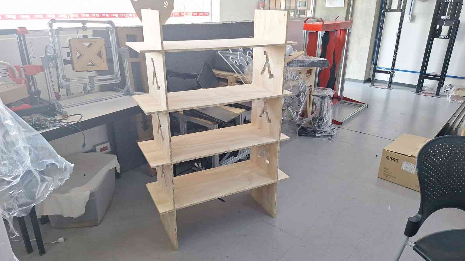
My design featured a rack that measured 137 centimeters tall, 90 centimeters wide, and 35 centimeters deep. I chose this design because I am currently enrolled in the Fab Academy outside of my hometown, Veracruz, and the flat I am renting is quite small. I had previously purchased a rack for storing clothes and other items, but I needed an additional one. I thought, why buy another rack when I could make one myself?
I based the dimensions and layout of this rack on the one I purchased at Home Depot. I wanted to replicate the existing rack. My design consists of two vertical pieces connected by shelves, over which I plan to accommodate some items I had to leave in my luggage.
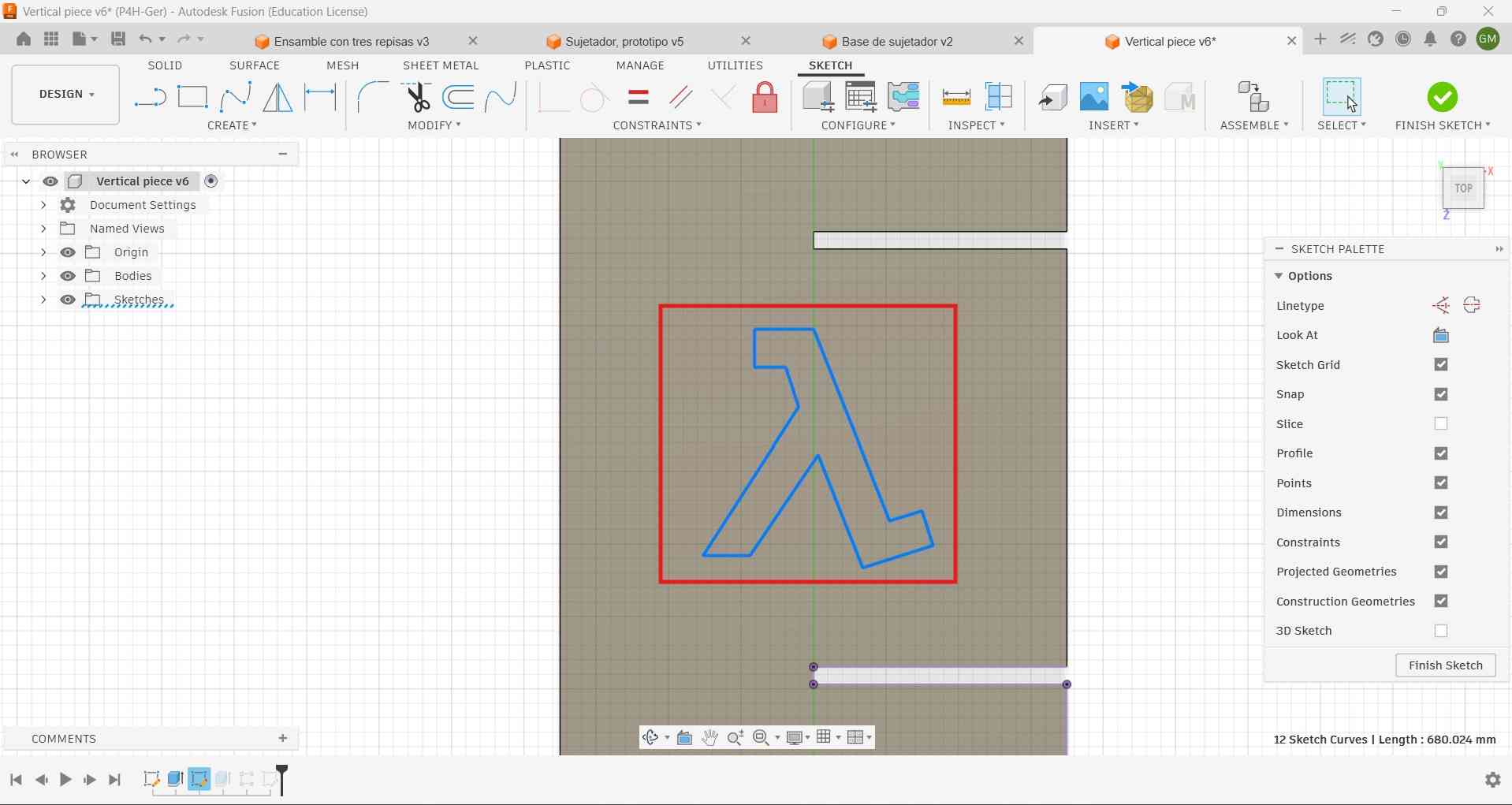
I designed the CAD model of the rack using Fusion 360. The images below display the isometric, side, and front views of the assembled rack.


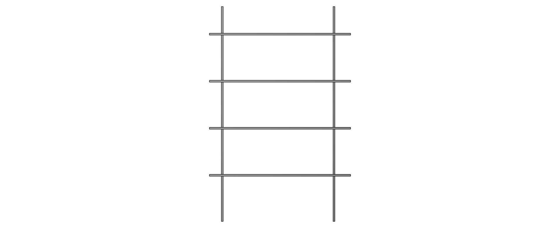
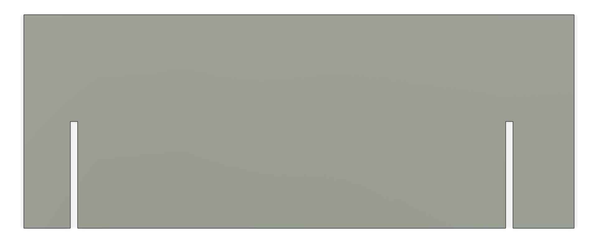
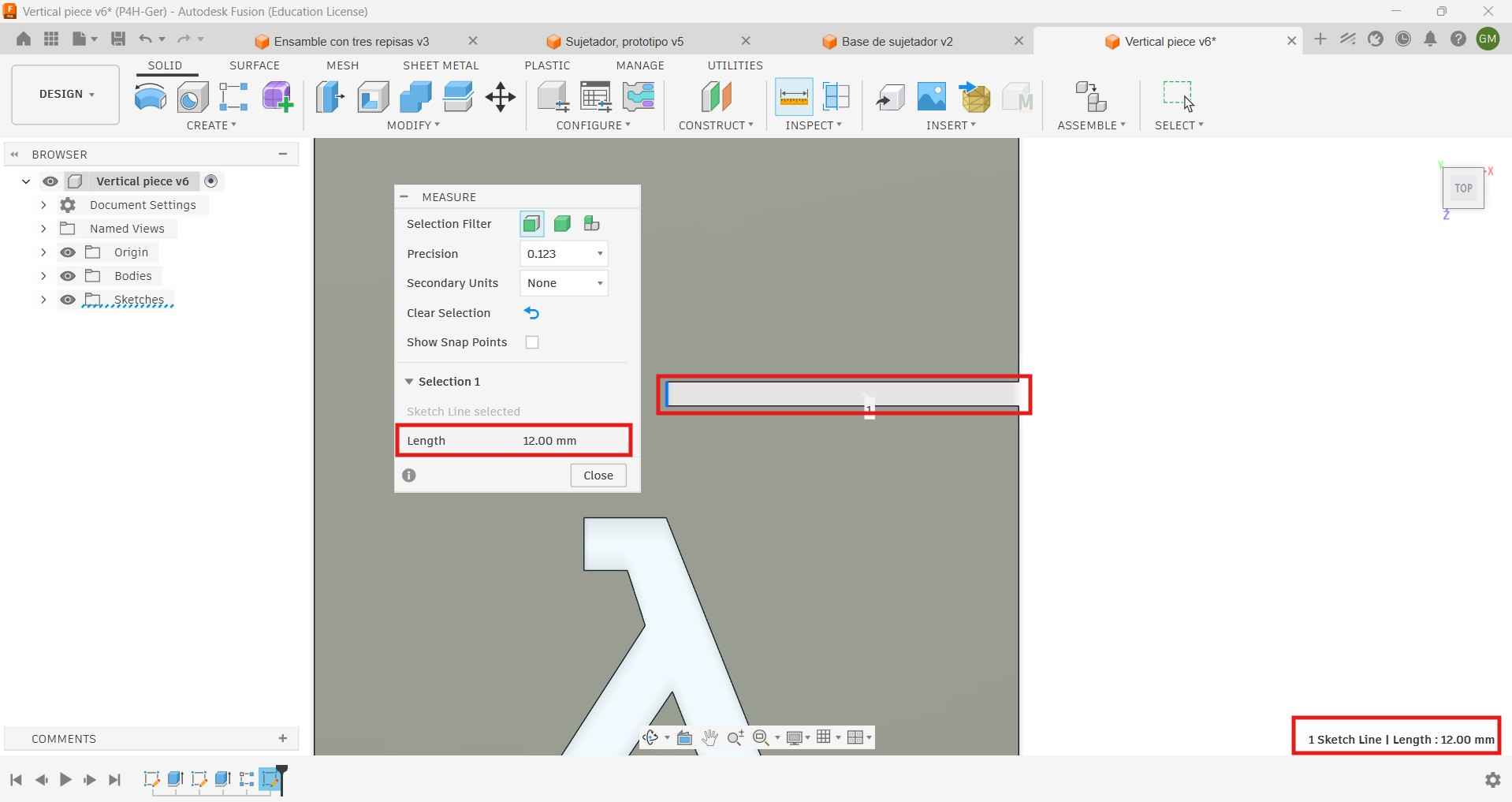
I designed the rack to be assembled without glue, nails, or screws, using slots and press-fit joints instead. The slots have a thickness of 12 mm, which matches the thickness of the material.
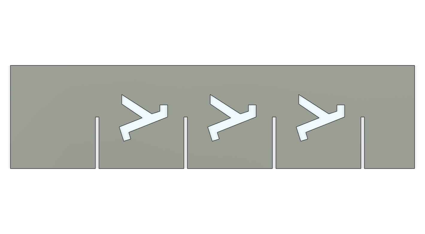
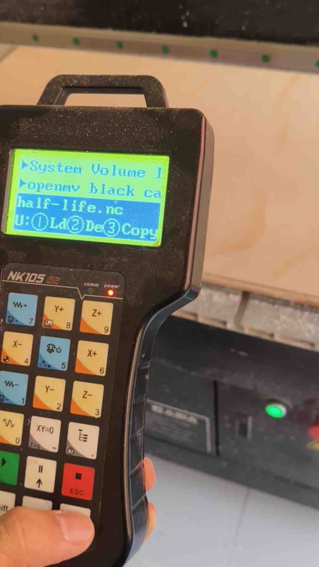
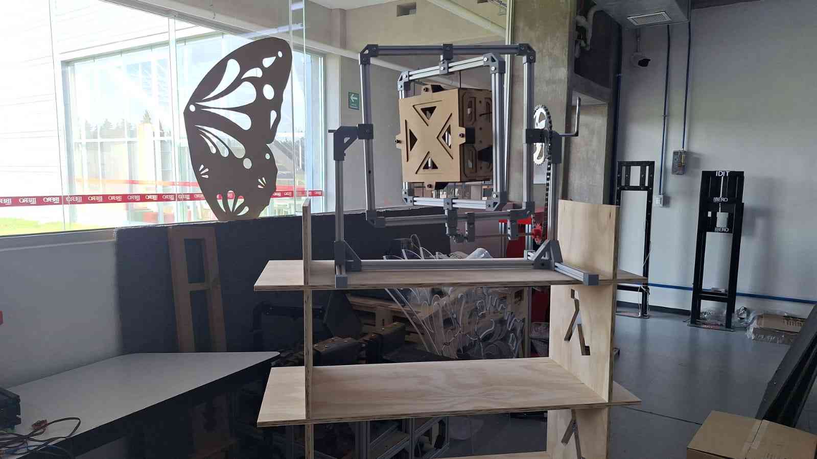
I included a Lambda symbol in my design as a tribute to the nickname given to me by a close group of friends. The Lambda is connected to the character Gordon Freeman from Half-Life, who is often described as the right man in the wrong place at the wrong time—something that resonates with how some people see me at times. I cherish the memories I have with those friends, which is why the Lambda symbol holds special significance for me. I got the Lambda outline from this site .
3. Toolpath generation.
Toolpaths for CNC machining start similarly to laser cutting; we must first create DXF files for each component, and then we have to export those files to V-Carve.
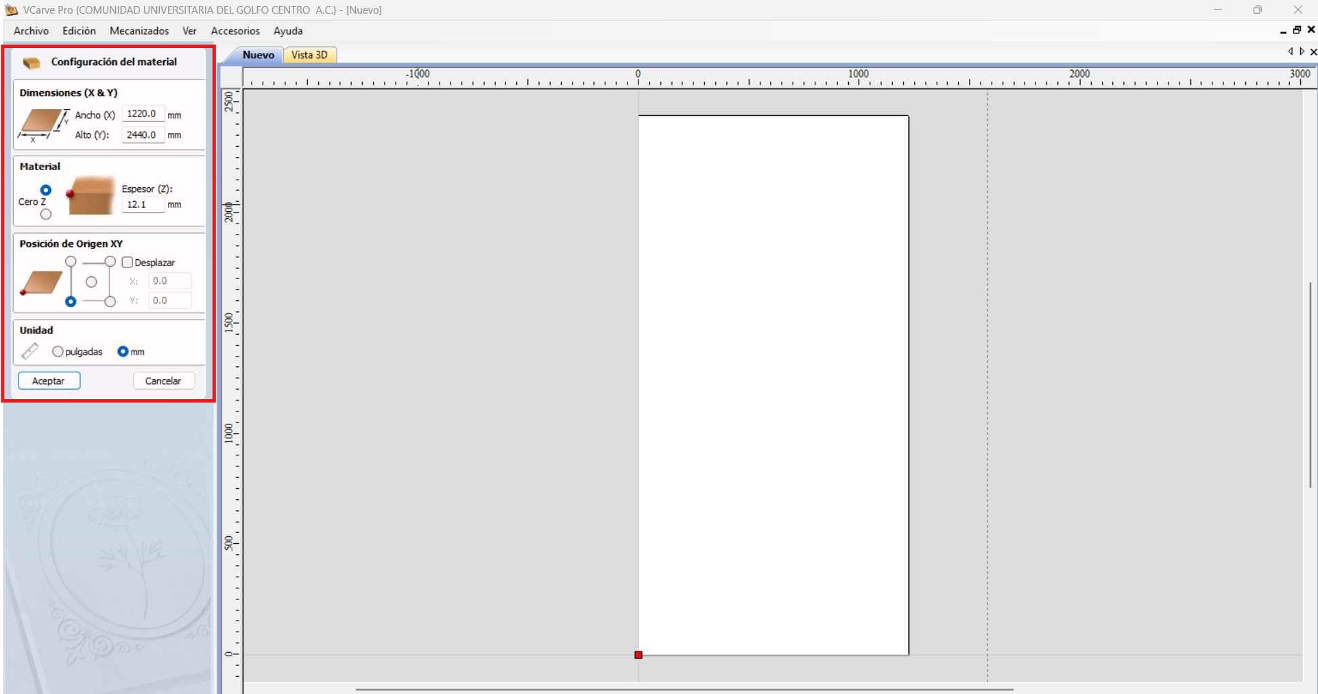
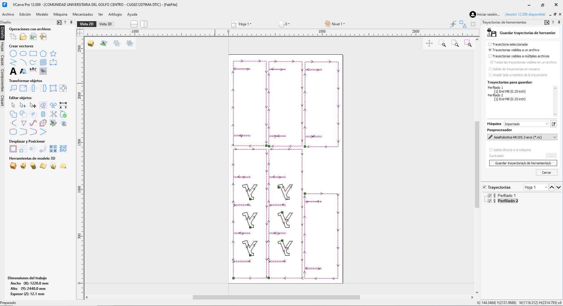
Before importing the files to VCarve, we need to configure the material settings. I established the material dimensions as X = 1220.0 mm, Y = 2440.0 mm, and Z = 12.1 mm. I chose millimeters as the project's unit.
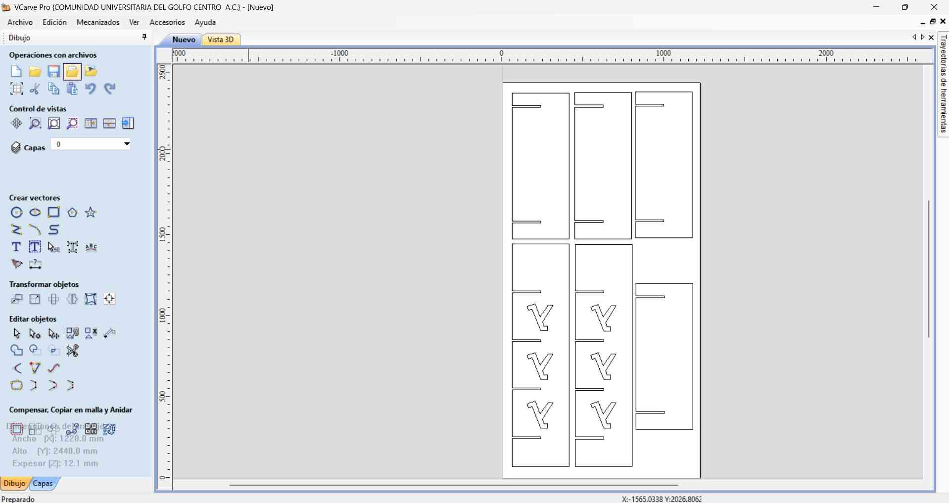
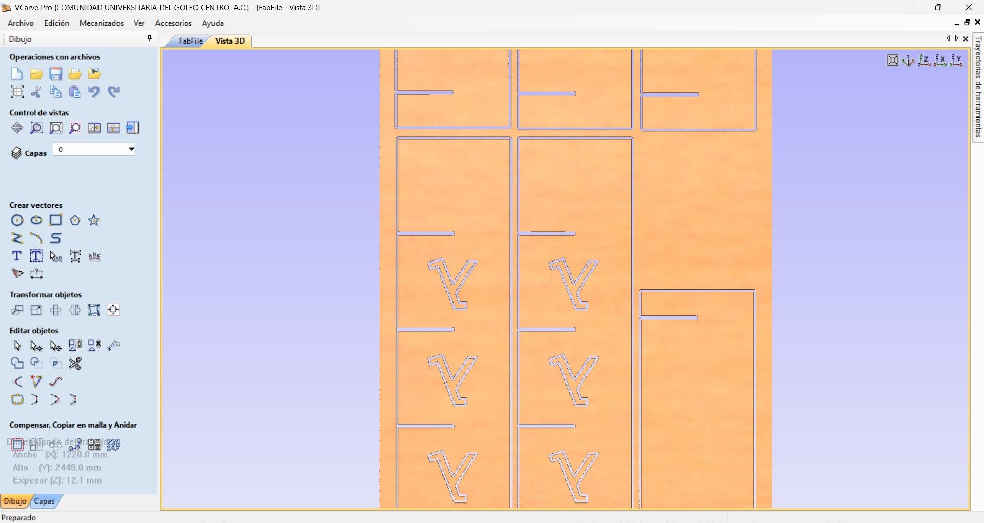
After setting the material parameters, you can import DXF files by using the File tab in the upper bar of the VCarve main window. Imported files will appear outlined in purple. I initially had trouble moving my vertical pieces and the Lambdas as a single unit. However, I resolved this by selecting both the Lambdas and the vertical component, then dragging them together.
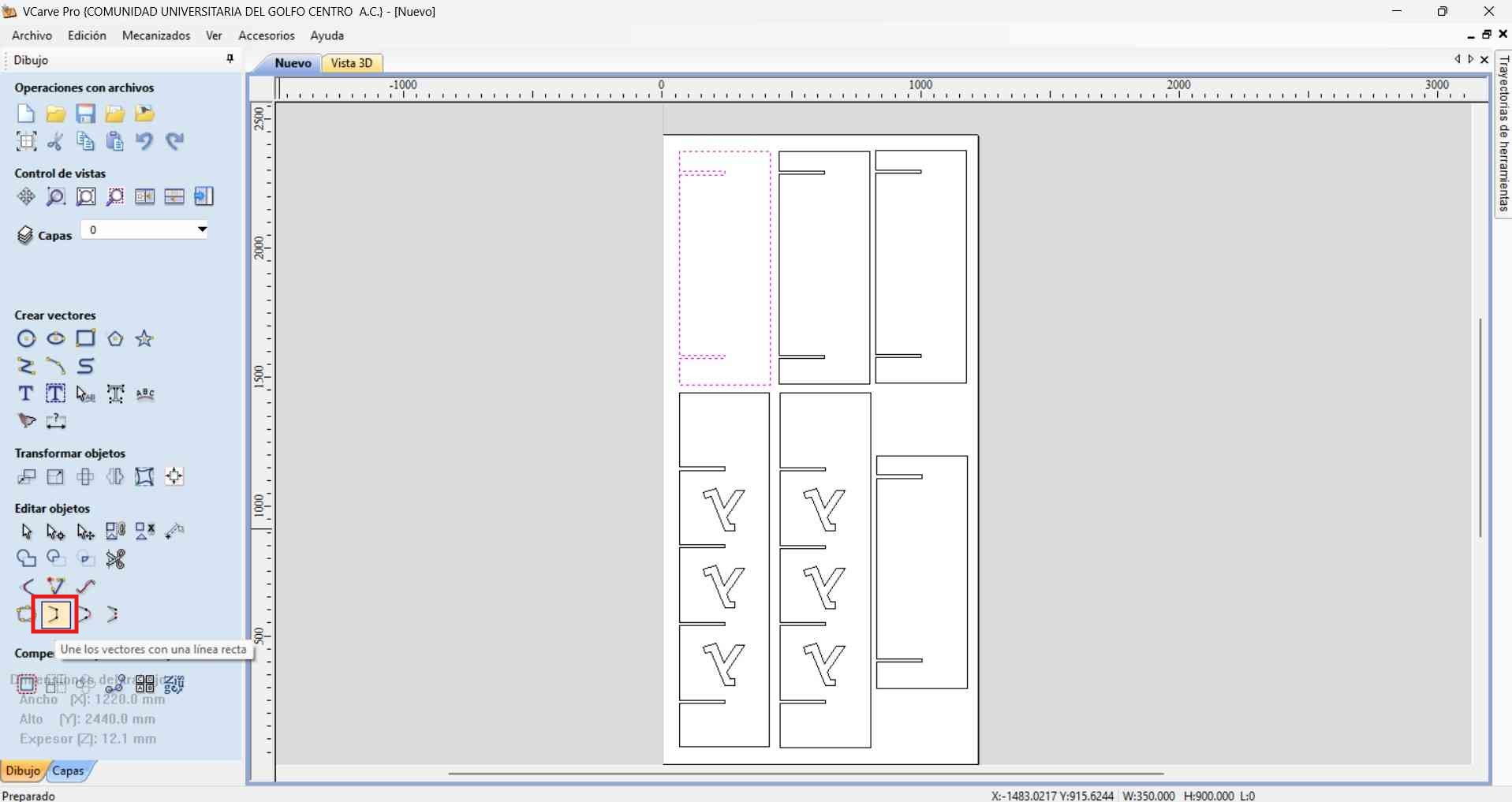
It’s important to join the vectors from imported DXF files, as failing to do so can result in discontinuous machining paths. If the vectors aren’t joined, the machine will interpret them as separate dotted lines rather than a single continuous path.
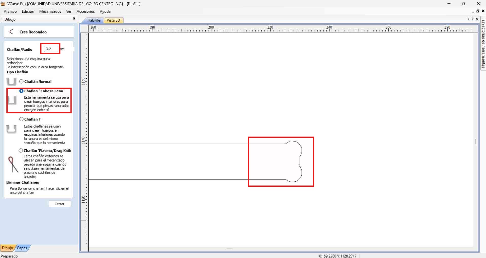
When CNC machining internal corners, particularly in slots or pockets designed to fit square or rectangular mating parts, the round cutting tool leaves a filleted (rounded) internal corner due to its radius. This fillet prevents square-edged parts from seating fully, as the sharp edges of the part cannot fit into the rounded corner.
Dog-bone chamfers solve this by adding a circular cut (the “dog bone”) at each corner. This is typically done by positioning the tool so that it plunges into the corner, extending just outside the standard slot profile, creating an undercut that allows the mating part’s sharp corner to fully seat.
- Tool diameter : The diameter of the dog-bone cut should match the tool diameter, ensuring complete clearance.
- Placement :The center of the dog-bone circle should be aligned so it touches both walls of the slot at the corner.
- Result: The slot, whn viewed from above, looks like it has "bones" at each corner, hence the name.
I applied femur head chamfers with a 3.2 mm radius. I chose this dimension because it matched the cutting tool that I would be using on the CNC router. By applying these chamfers to every slot in the design, I ensured that the pieces would fit firmly.
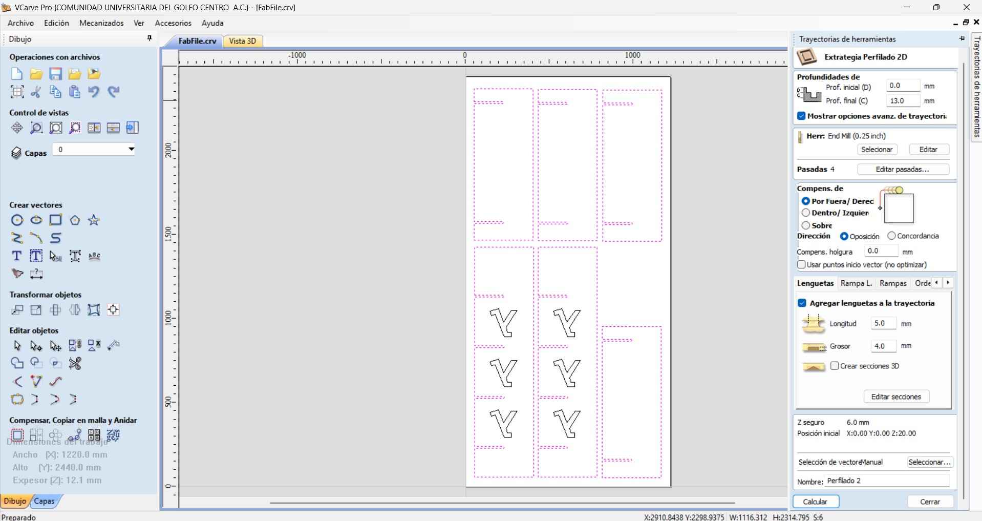
While working in VCarve, I set my cutting tool to a 0.25-inch two-flute end mill. The spindle speed is configured at 18,000 RPM, with a feed rate of 2,000 mm/min and a plunge speed of 600 mm/min.
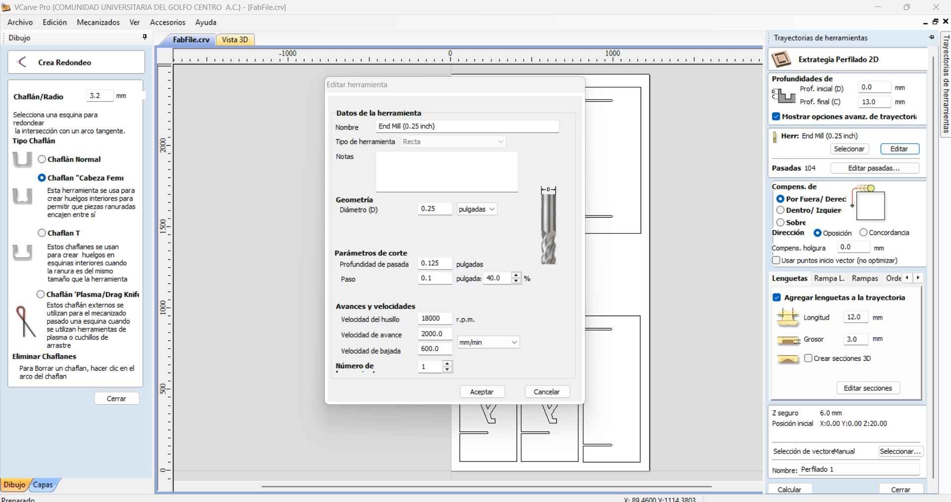
I created the machine toolpath using a 2D profiling method for extraction. I specified the end-cut depth as 13 mm to ensure that the tool effectively cuts through the plywood sheet.
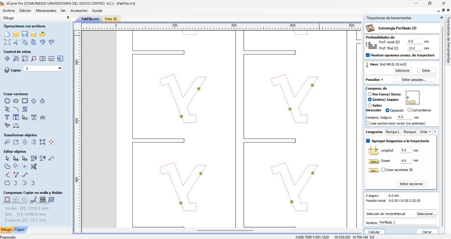
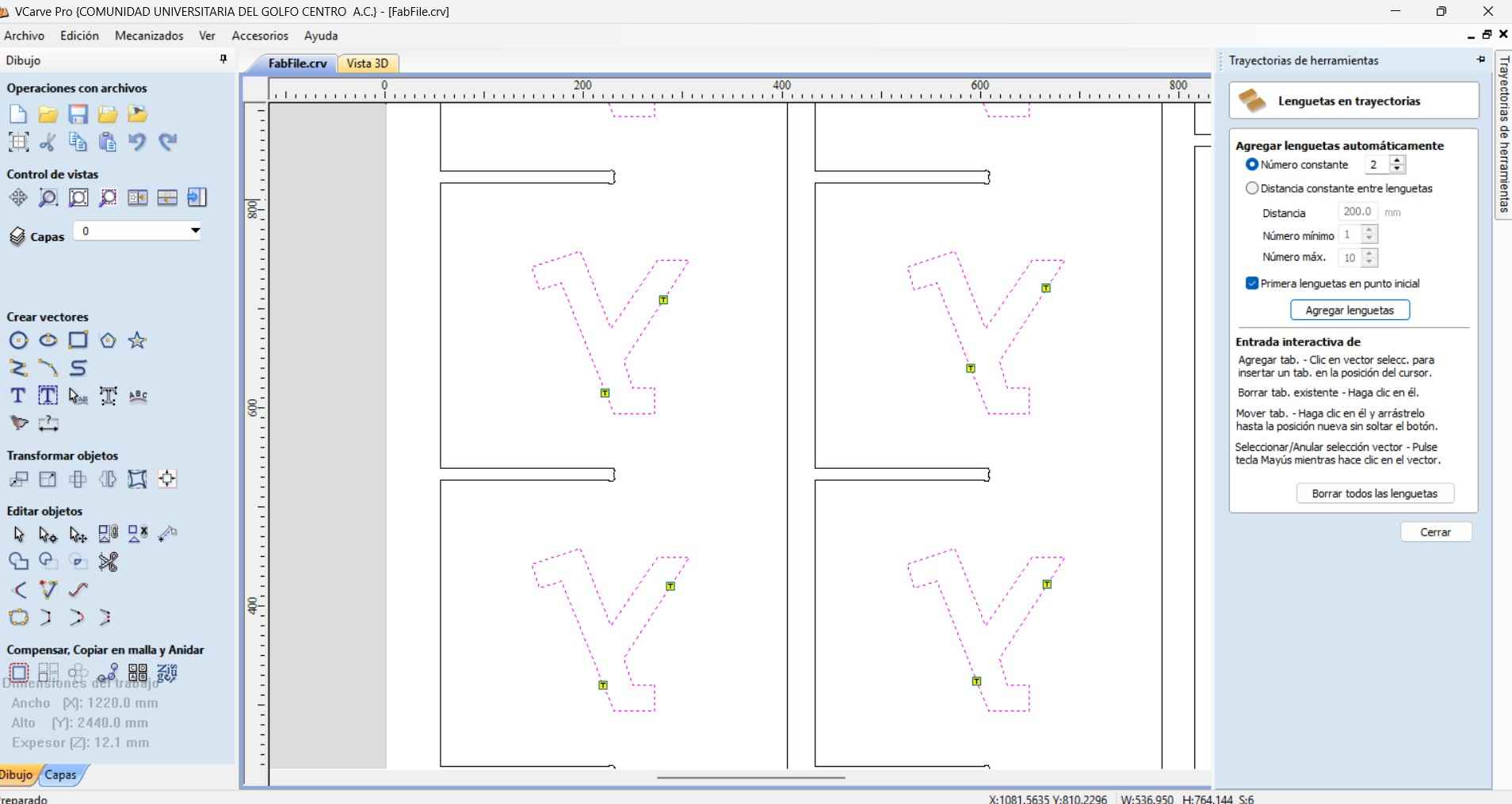
I placed 2 trajectory tabs per component to prevent each milled component from popping off the plywood sheet during a milling operation.
The trajectory tabs were created with a length of 5.0 mm and a depth of 4.0 mm.
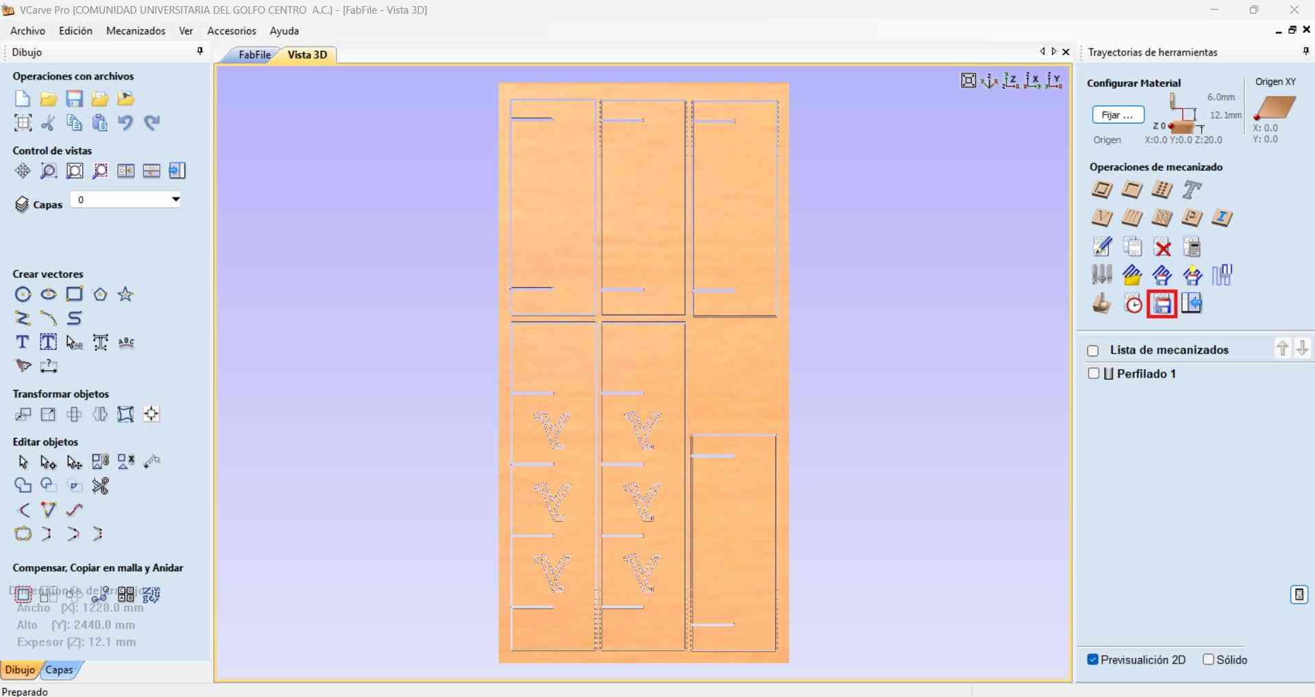
After confirming that the toolpath simulation could generate the desired result, I proceeded to export the toolpath file for the CNC router.
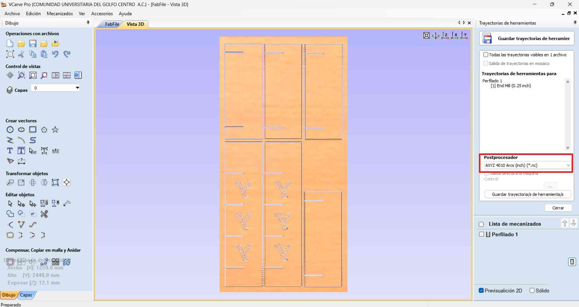
Before generating the toolpath, I needed to transfer my design file to another computer equipped with a newer version of VCarve. My current (older) version of VCarve was unable to generate the required toolpath using the AsiaRobotika-NK105.3-arcs post-processor. This post-processor is essential for creating compatible G-code for the Asia Robotics CNC machine located at Fab Lab Ibero Puebla.
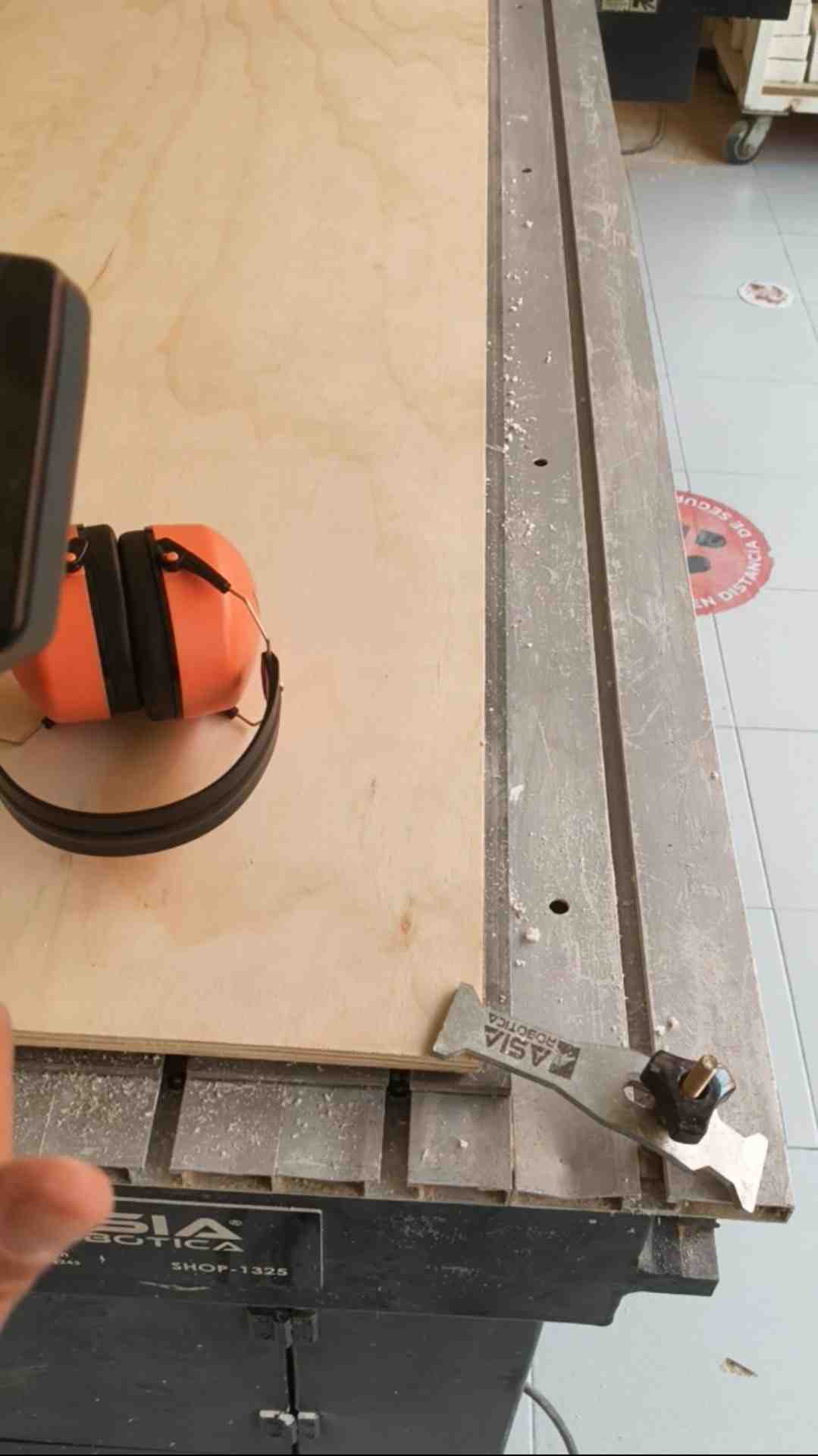
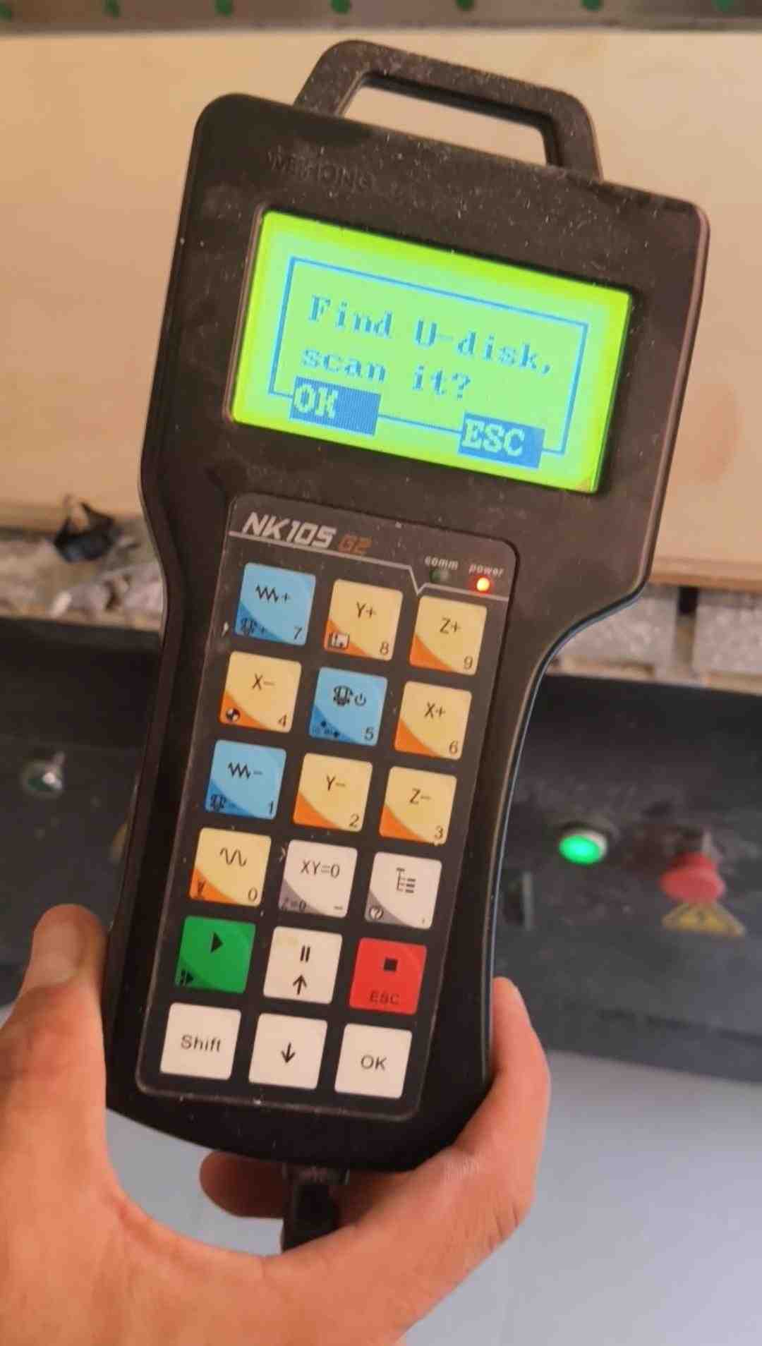
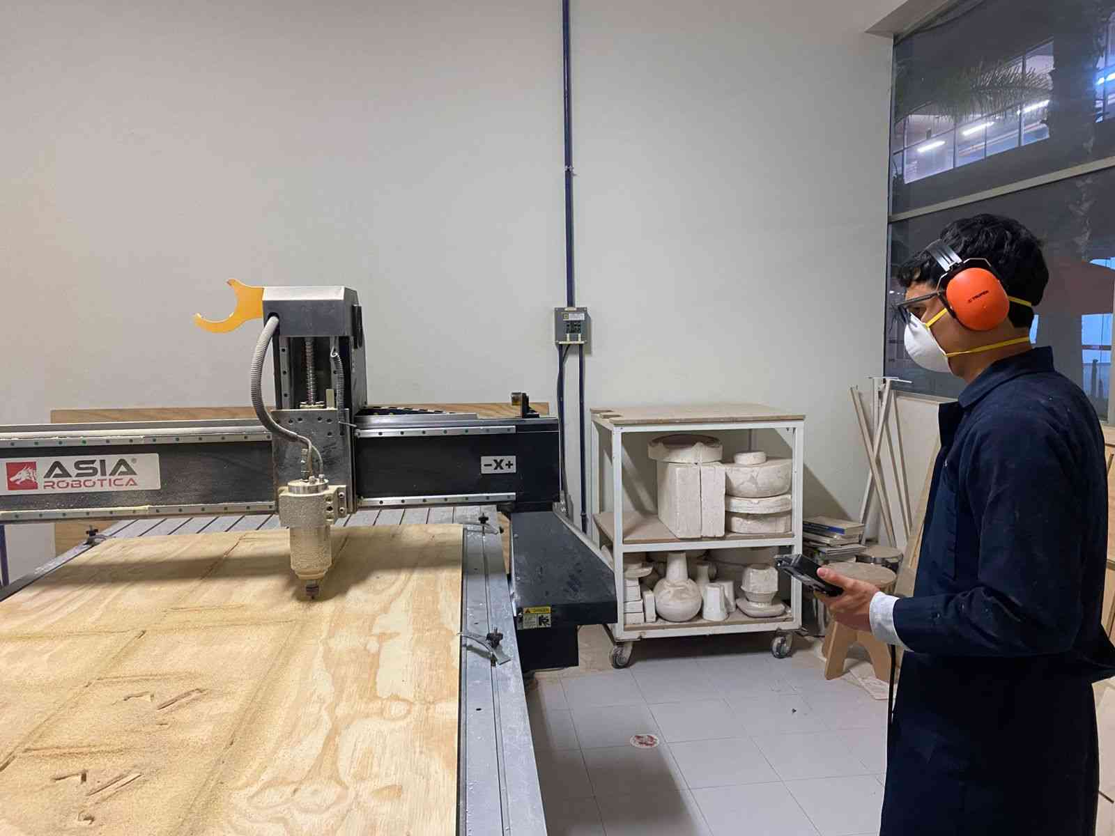
4. Machine operation
With the toolpath successfully generated, it was finally machining time. However, before beginning any milling operations, I made sure to follow all necessary safety protocols. This included putting on the required protective gear:
- Steel-toe-boots : Foot protection against heavy objects or dropped tools.
- Face mask : Respiratory protection against fine dust and debris generated during milling.
- Lab coat : Body protection for skin and clothingagainst chemicals and other hazards.
- Audio protection headset : To prevent hearing damage from prolonged exposure to lloud machinery.
Once properly equipped, I proceeded to set up the milling operation, confident that all safety measures were in place.
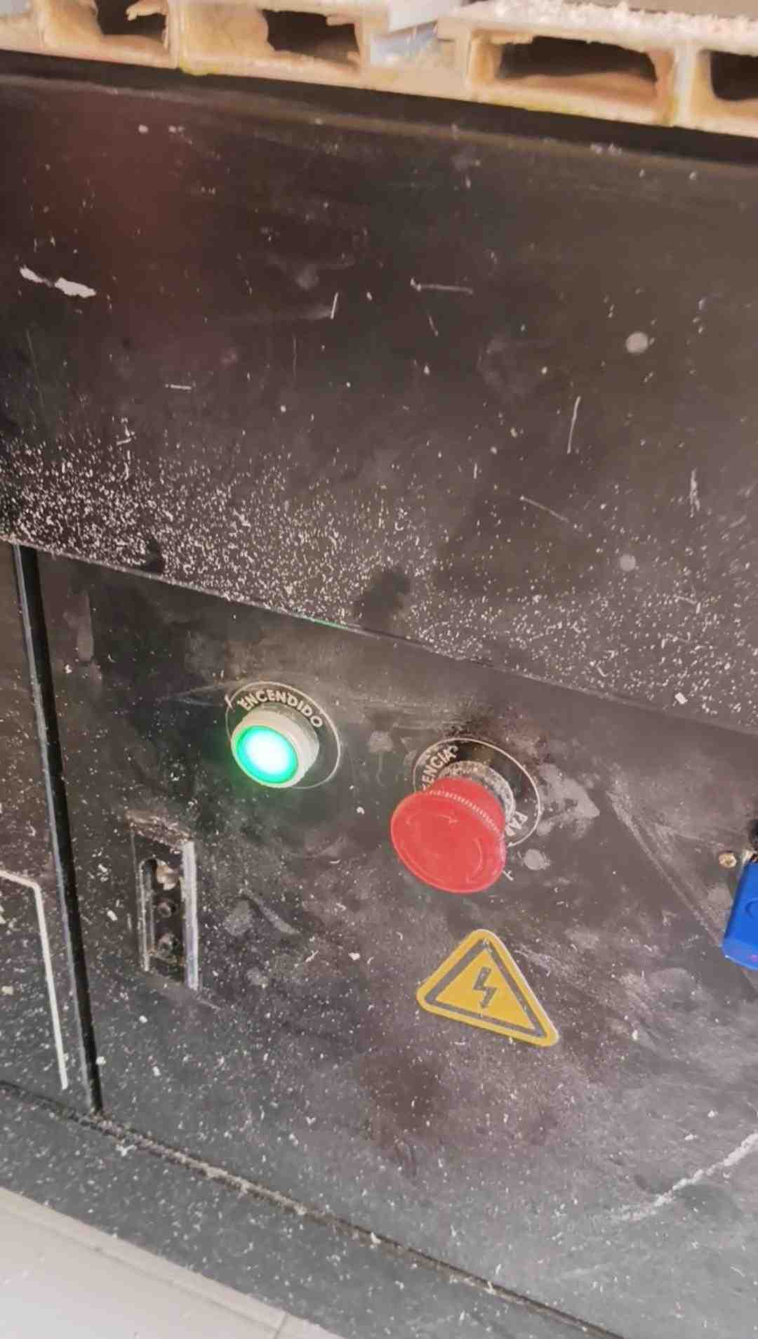
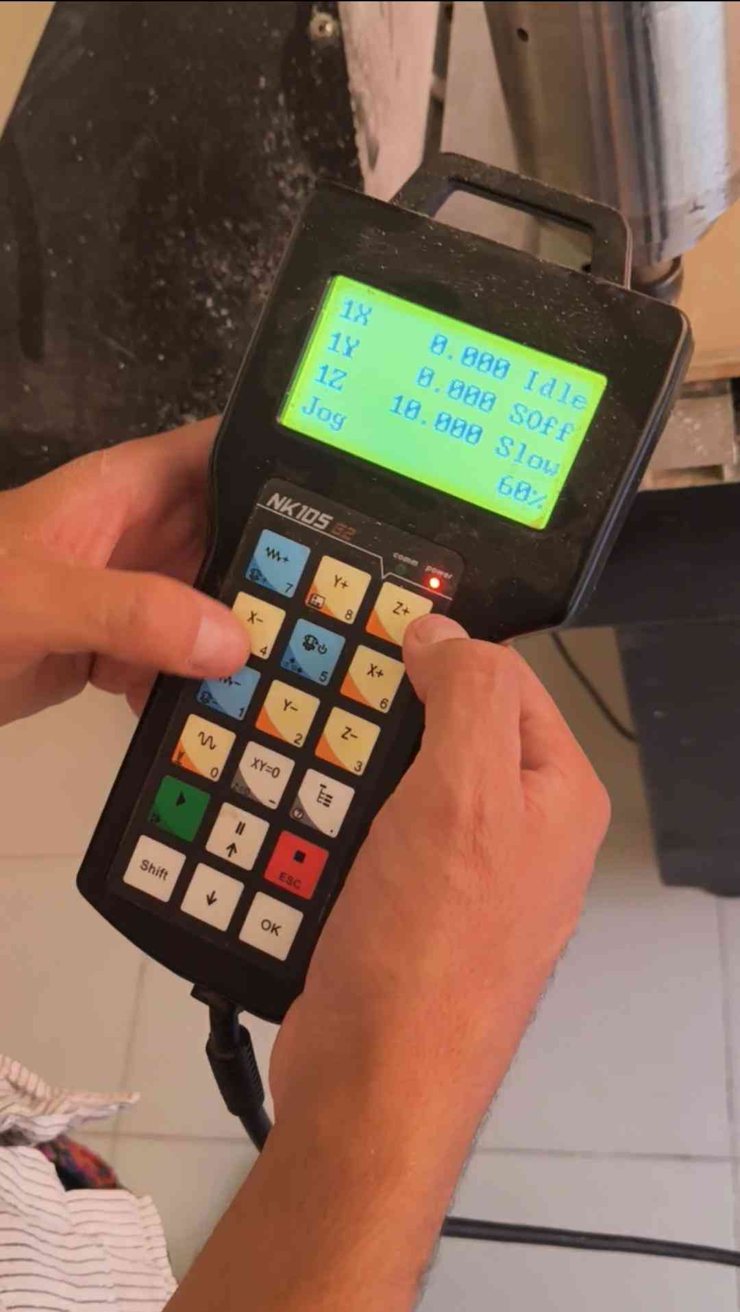
Before proceeding with the machine setup, I’d like to provide a brief overview of the functions of each button on the CNC controller. Understanding these controls is essential for safe and efficient machine operation.
| Key name | Color | Primary function | With Shift (auxiliary key) |
|---|---|---|---|
| Motion keys | |||
Y+ | Tan | Move Y-axis positive; input number 8 | Switch between MCS and WCS |
Z+ | Tan | Move Z-axis positive; input number 9 | — |
X- | Tan | Move X-axis negative; input number 4 | Home all axes |
X+ | Tan | Move X-axis positive; input number 6 | — |
Y- | Tan | Move Y-axis negative; input number 2 | First tool measurement |
Z- | Tan | Move Z-axis negative; input number 3 | Measurement after tool change |
| Speed & override keys | |||
Override+ | Blue | Increase feedrate override; input number 7 | Increase spindle gear (if spindle port has input) |
Override- | Blue | Decrease feedrate override; input number 1 | Decrease spindle gear (if spindle port has input) |
Speed switchover | White | Switch jog / rapid jog speed; input number 0 | Tool measurement |
| Function keys | |||
Spindle ON/OFF | Blue | Start or stop spindle (manual mode); input number 5 | Back to workpiece origin |
Clearing (XY=0) | White | Clear XY to zero; input minus sign | Clear Z to zero |
Menu (T≡) | White | Enter menu page; input decimal point | Enter image update page at system start-up |
| Control keys | |||
Start ▶ | Green | Start program execution | Breakpoint resume |
Up / Pause ⏸ | White | Suspend processing; up direction key | — |
ESC ■ | Red | Stop processing; cancel selections, inputs and operations | — |
Shift | White | Auxiliary / modifier key; switch stepping ↔ jog mode on machining page | — |
Down ↓ | White | Down direction key | — |
OK | White | Enter jog/rapid jog speed adjustment page (in menu); confirm selections, inputs and operations | — |
5. Results
6. Files
Here are the downloadable files for this week:
DXF and VCarve files for the rack design and toolpaths.Reflection
I must admit, I was initially nervous about using machines larger than myself during Fab Academy. However, overcoming that fear was necessary in order to complete this assignment. I’m pleased to say that everything went according to plan, as I am writing this now. While I successfully machined my rack design, I believe the current build could benefit from additional rear supports, something to consider for the next iteration in a future development spiral!