Week 03 - Computer-Controlled Cutting
This week's assignment was about designing a parametric construction kit, as well as using a laser-cutting machine and a vinyl cutter. For this week's group assignment , the class underwent the lab's safety training, while the laser cutter's focus, power, speed, rate, kerf, joint clearance, and types were characterized.
Work log
1) Completed tasks
- Designed and documented a parametric construction kit taking into account the lasercutter kerf.
- Fabricated and evaluated the parametric construction kit.
- Cutted something on the vynil cutter.
1. What is a Computer-Controlled Cutting?
Computer-controlled cutting is a manufacturing process used to create shaped parts by following a digital design file. Instead of cutting manually, a 2D or 3D design is converted into toolpaths, which are then sent to a machine. The machine follows these programmed toolpaths to remove or separate material. This week, we utilized a laser cutter, a machine that burns or vaporizes material using a focused laser beam. In laser cutting, the laser is not infinitely thin; it has a small width that creates a narrow gap as it cuts. This gap is referred to as the laser kerf. The kerf impacts the final size of our parts. For example, if we design a 50 mm square and cut directly along the line, the final piece may be slightly smaller because the laser removes material along the path. If the laser has a kerf of 0.2 mm, the cut line removes about 0.2 mm of material. This consideration is particularly important for press-fit joints, slots and tabs, gears, interlocking parts, and precise mechanical assemblies.
2. Design of a parametric construction kit
Before starting this assignment, I had a phone call with my dad, who is a high school teacher, and he told me how nice it would be to have a kit comprised of different polygons that could be assembled and disassembled. So, I settled for a parametric kit composed of polygons.
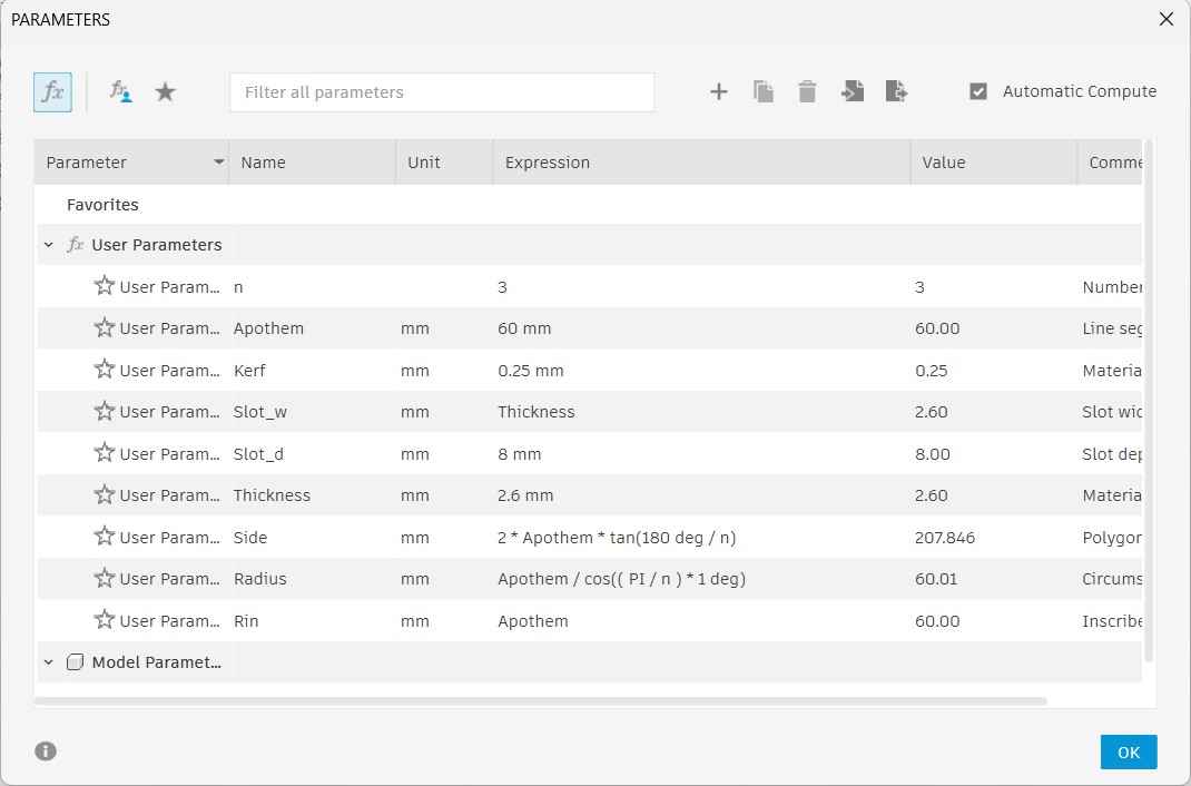
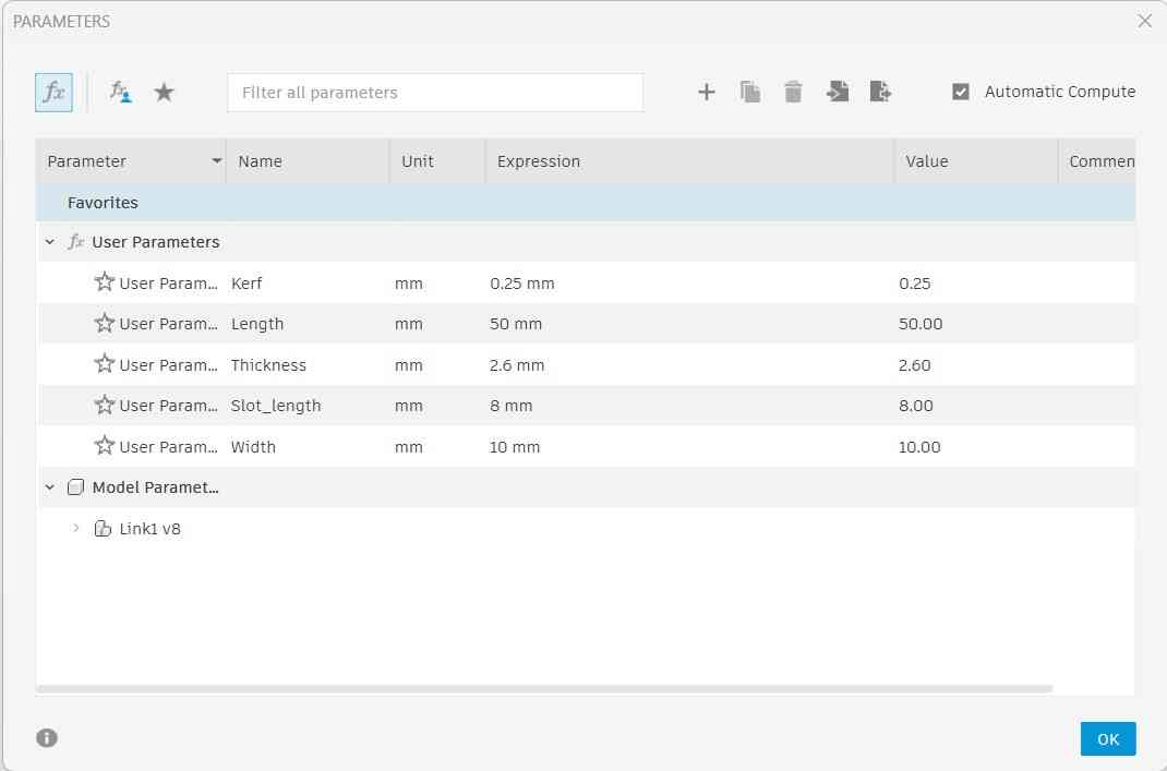
Fusion is my go-to 3D modeling software, so I started my design by first defining the parameters for creating polygons. A parameter is a variable that can be adjusted to enforce changes across the design. These variables could be represented by a single constant value, a range of values, or an equation. Among these parameters, I also included the kerf, which was determined to be about 0.25 mm by my classmates who conducted this week's weekly assignment.
Parameters and their values are declared on Fusion 360 by accessing the Modify menu and selecting the Change parameters option. This action will prompt a chart to open in which users can declare new parameters with initial values and change them again by accessing said menu.
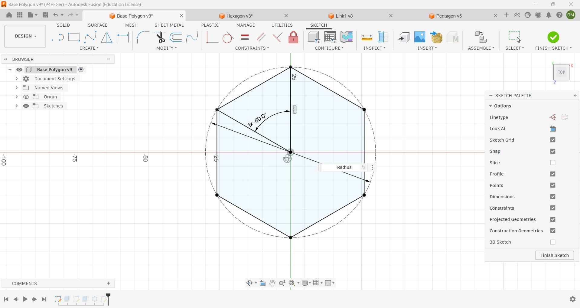
I started my design by creating a construction circle using the radius previously defined as a parameter.
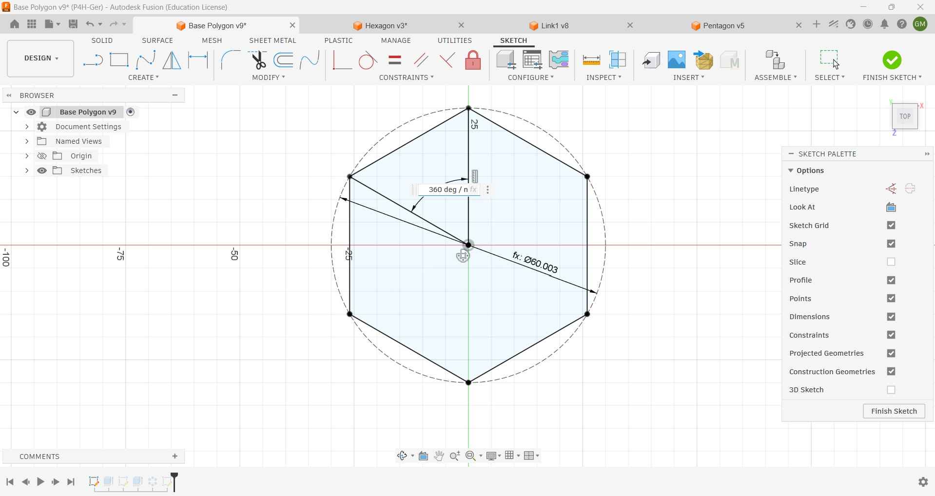
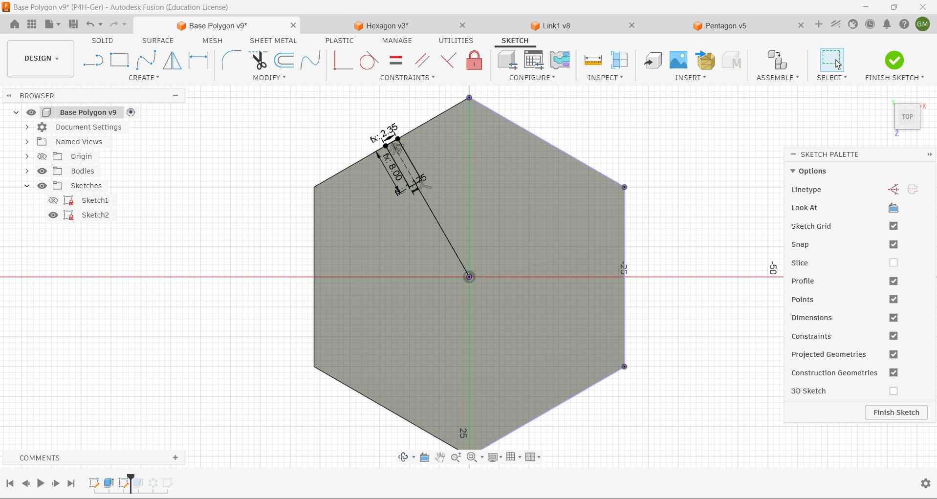
With the circle already drawn, I proceeded to draw an angle whose value was determined by dividing 360 degrees by the current number of sides, which is determined by the N parameter.
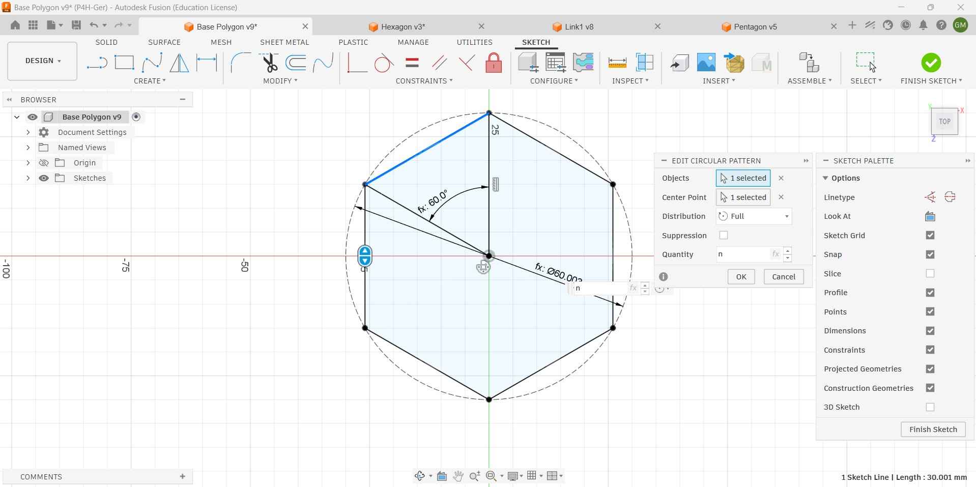
The drawn angle was the reference for the first line, which would be the polygon's side. This line would later be replicated around the circle using a circular pattern.
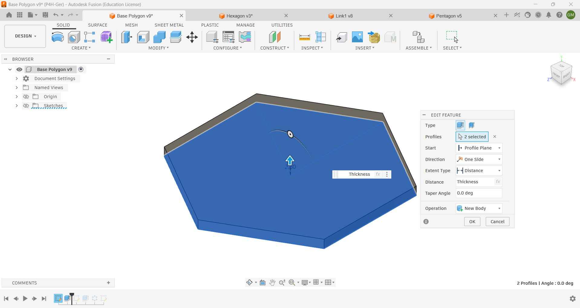
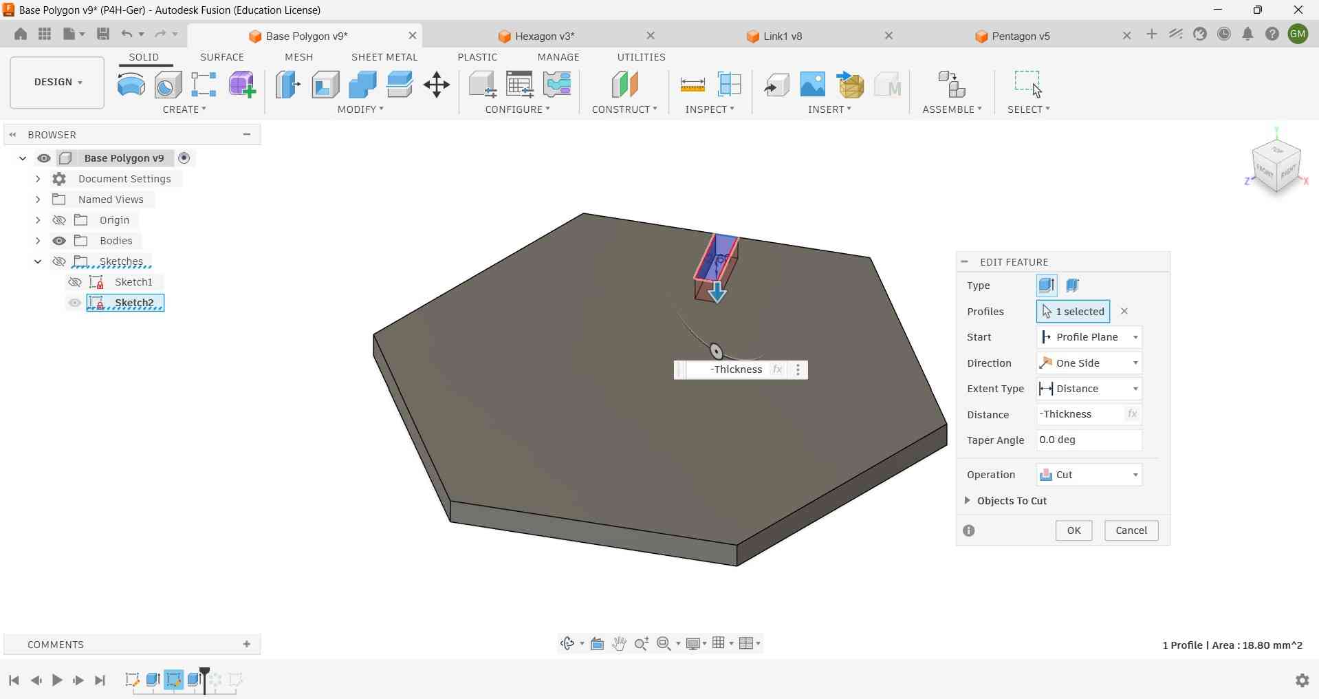
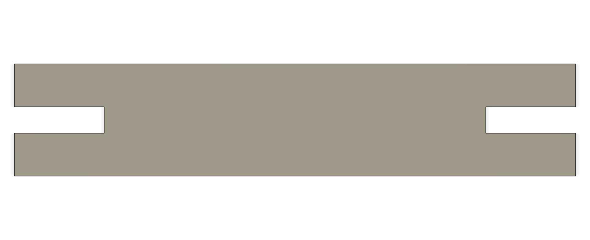
The finished sketch was extruded using the value that corresponded to the thickness of the MDF sheet provided by my FabLab.
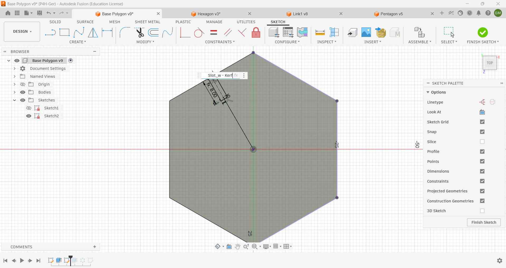
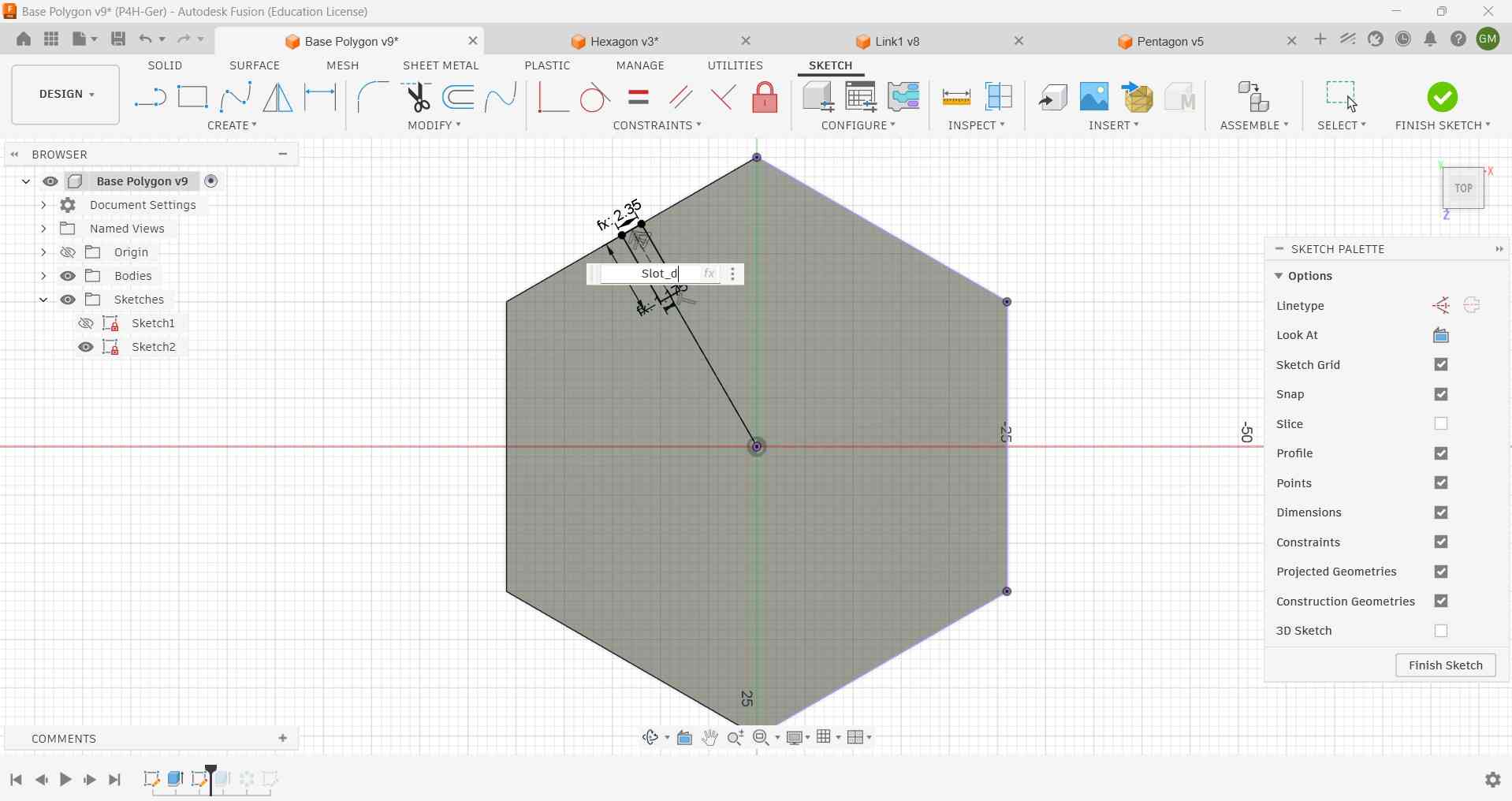
To assemble the kit, these polygons had to be fitted with slots that took into account the laser kerf.
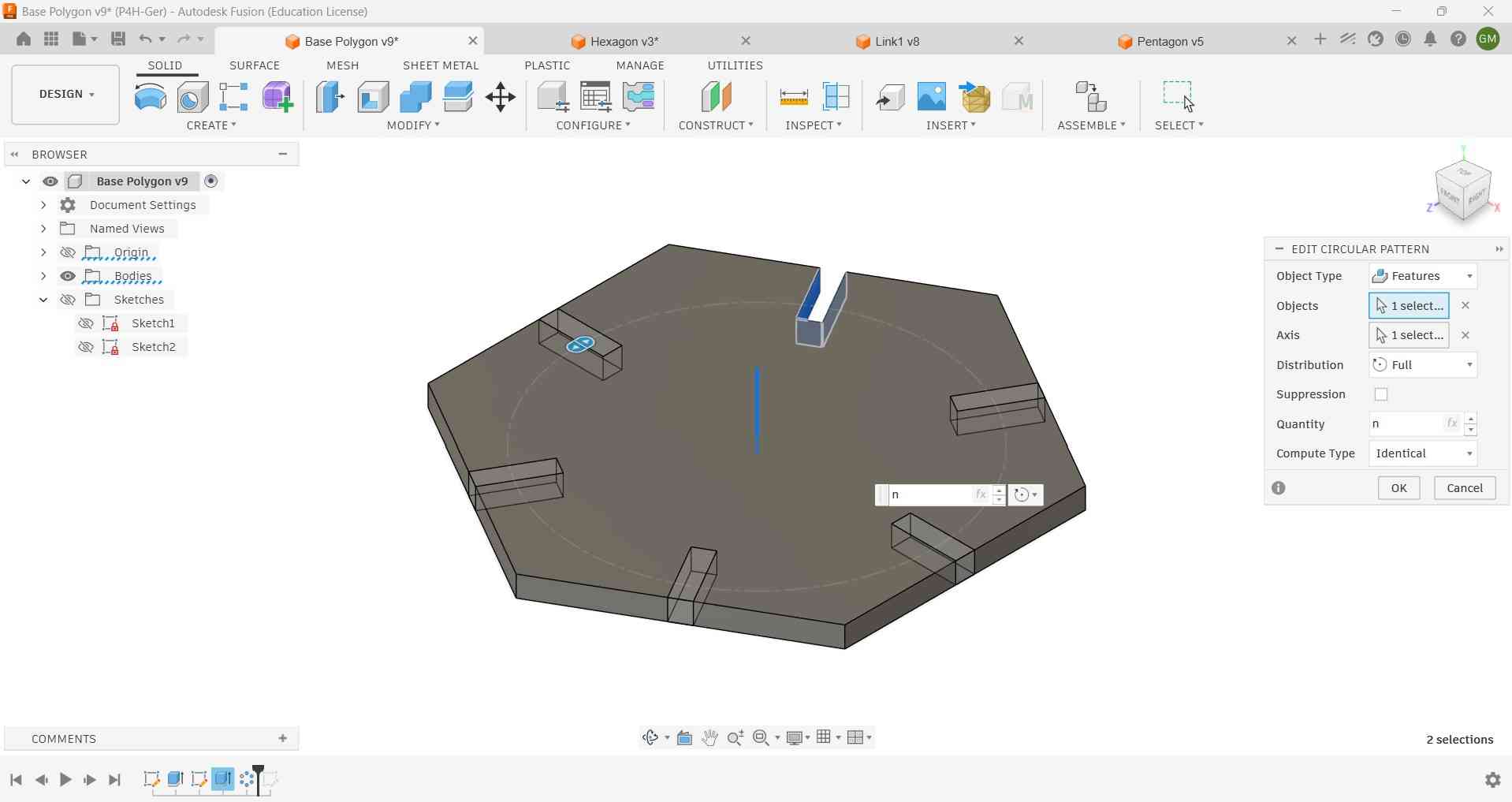
The drawn slot was extruded through the entire geometry. To ensure that each polygon numbered the slots equal to its number of sides, additional slots were created using a circular pattern. This pattern utilized the number of sides, denoted as N, as an input parameter.
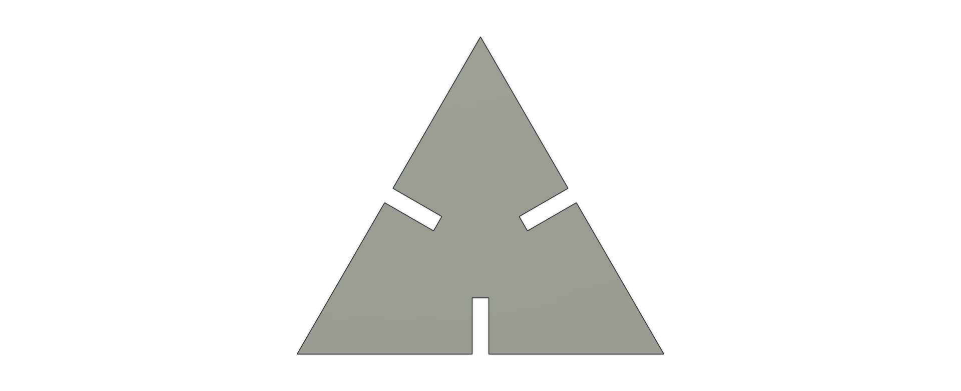
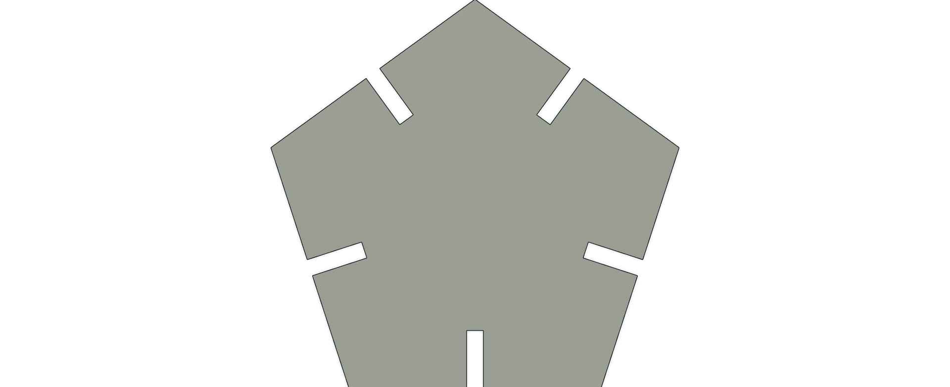
The resulting polygon could be altered by changing the value of the parameter N, which resulted in a triangle, pentagon, and hexagon.
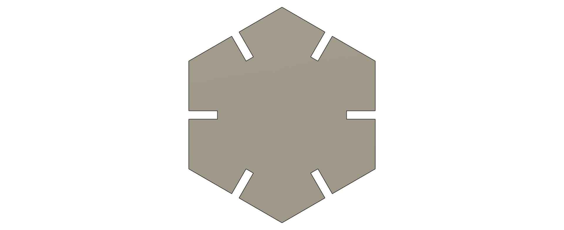
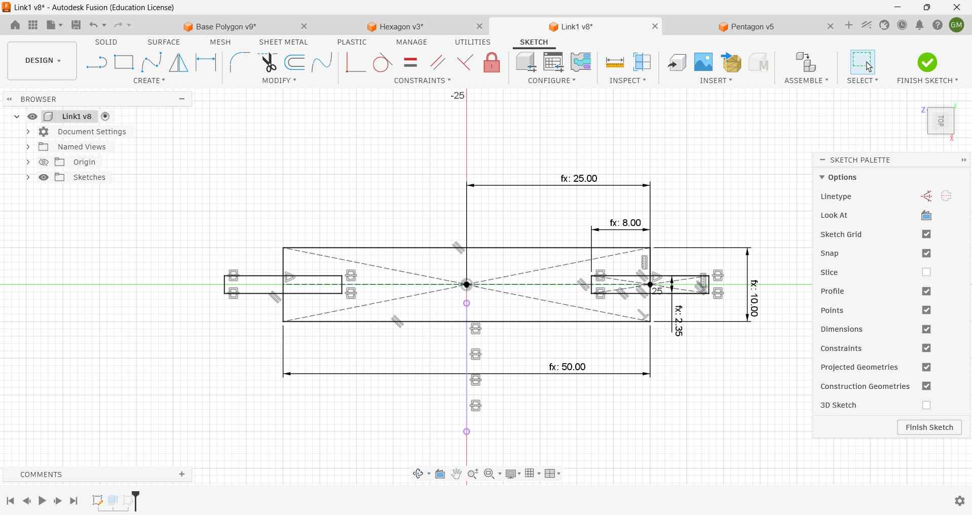
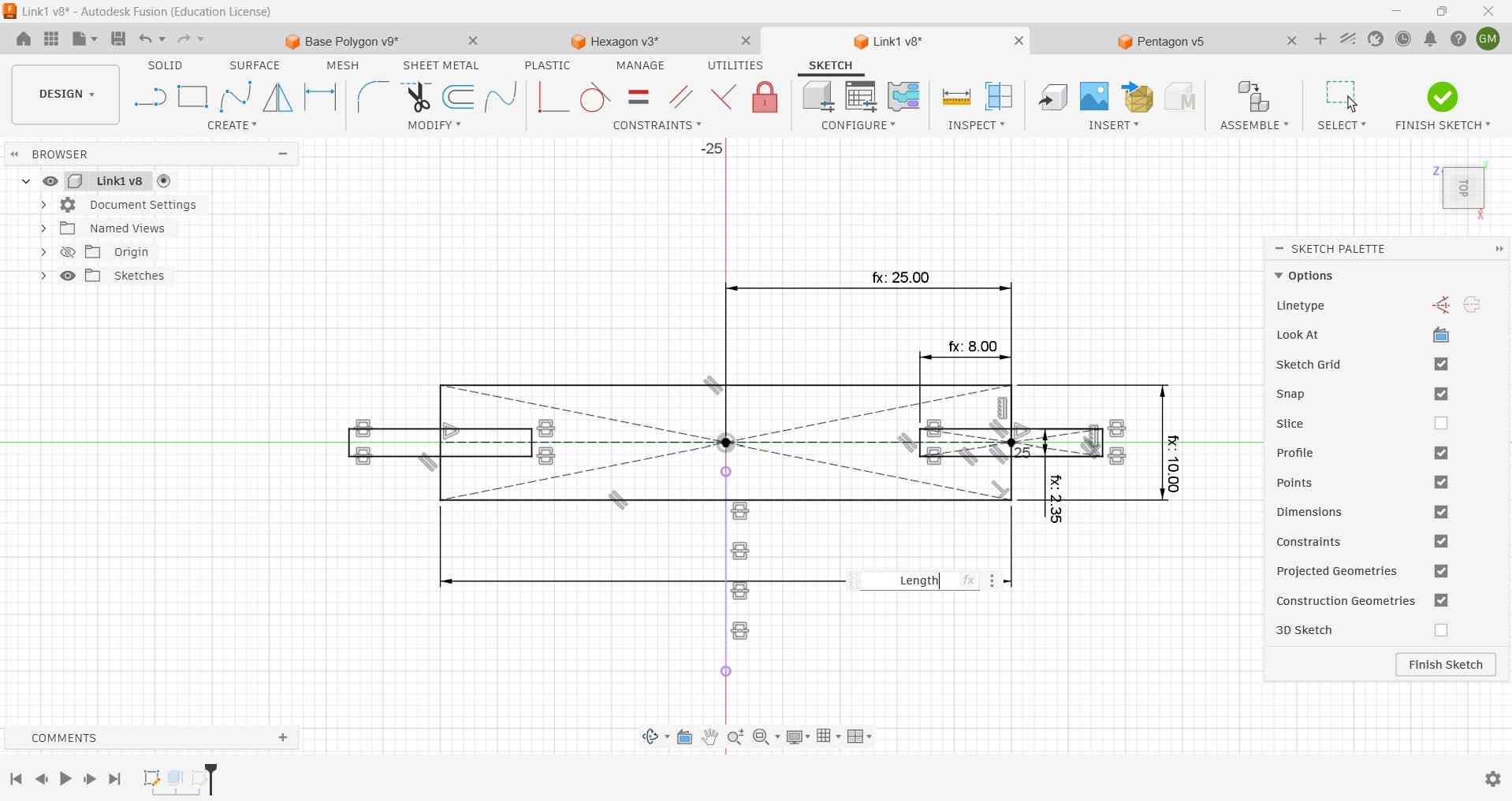
Another element included in the kit was a link piece, which was also designed in a parametric fashion to take into account the laser kerf.
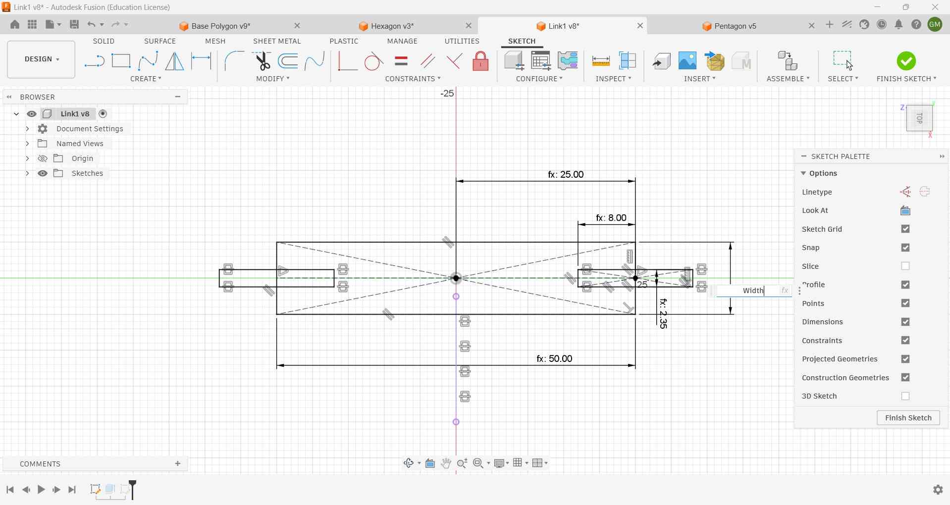
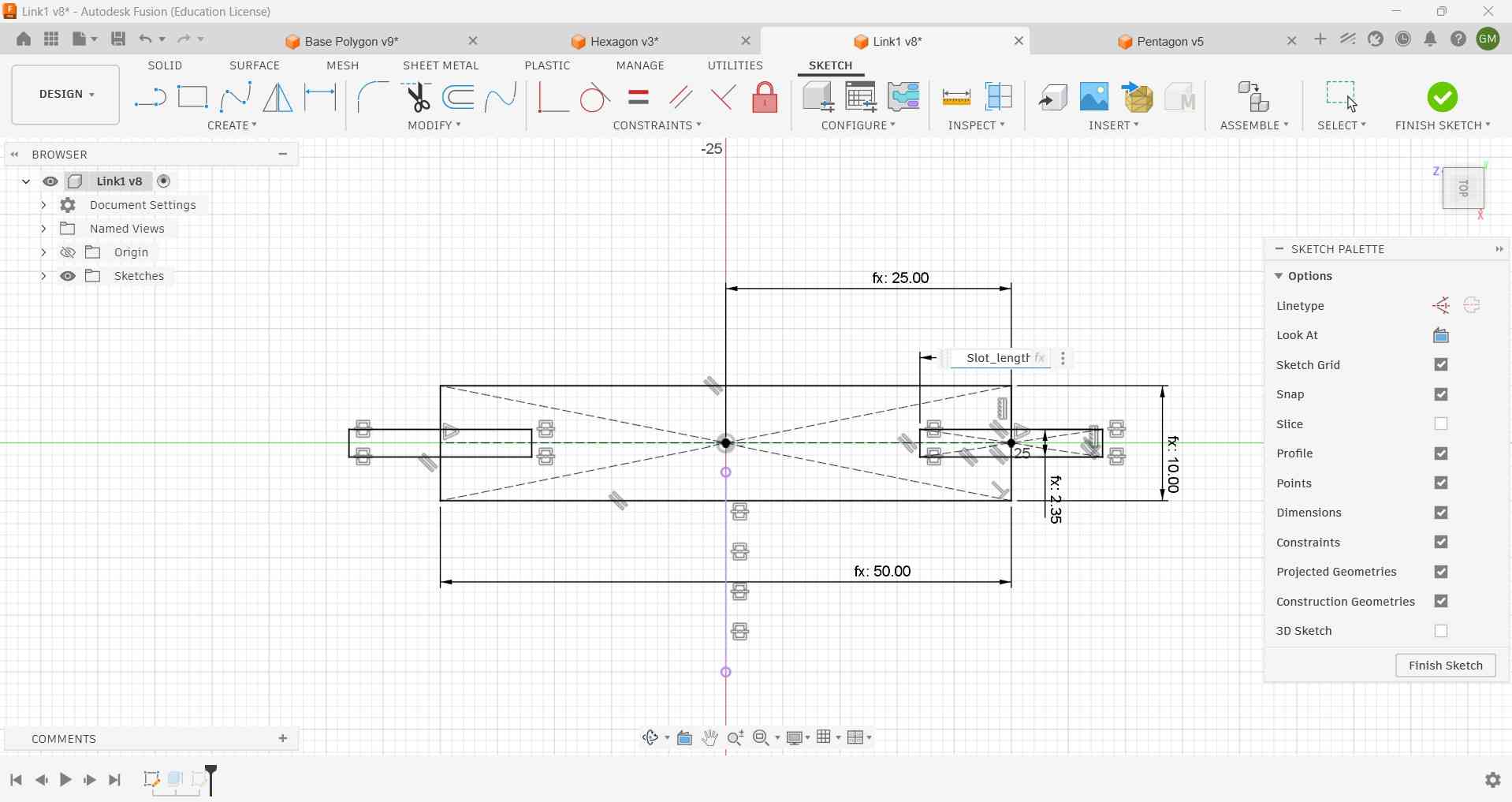
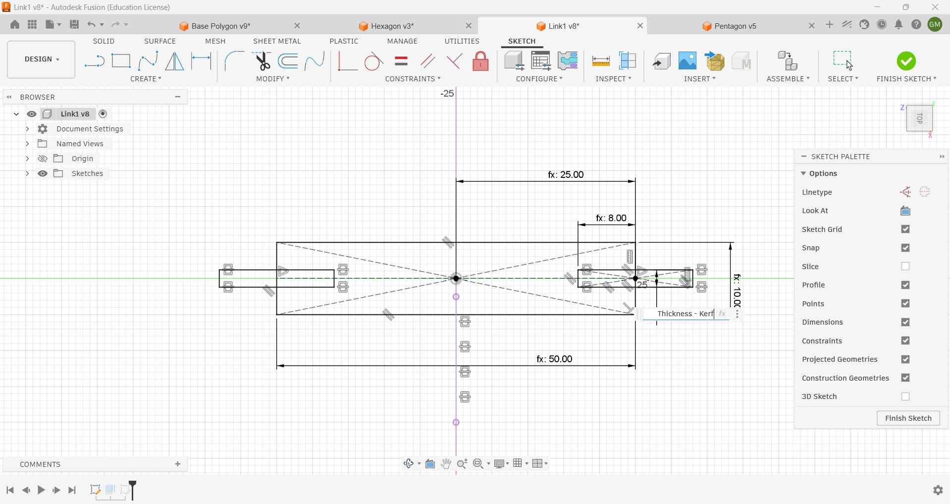
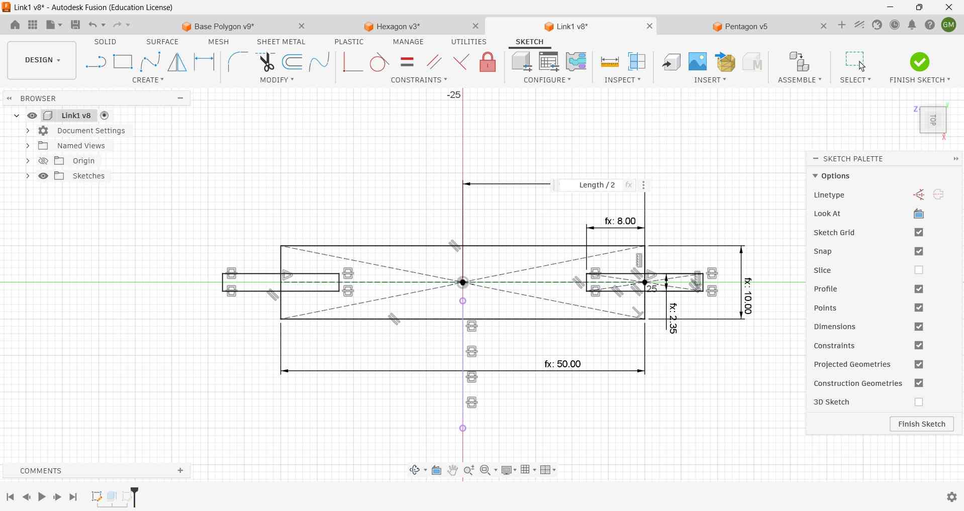
The following video shows the validation of the parametric properties of the kit:
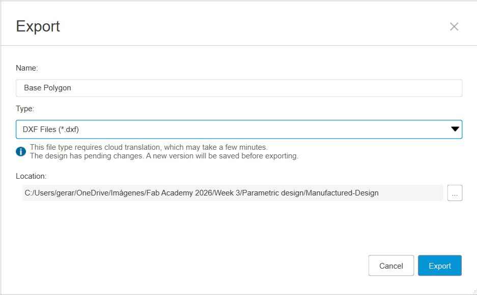
After completing and validating the design, the DXF files must be exported for laser cutting. In Fusion360, this can be done by selecting the export option under the File menu.
3. Laser cutting
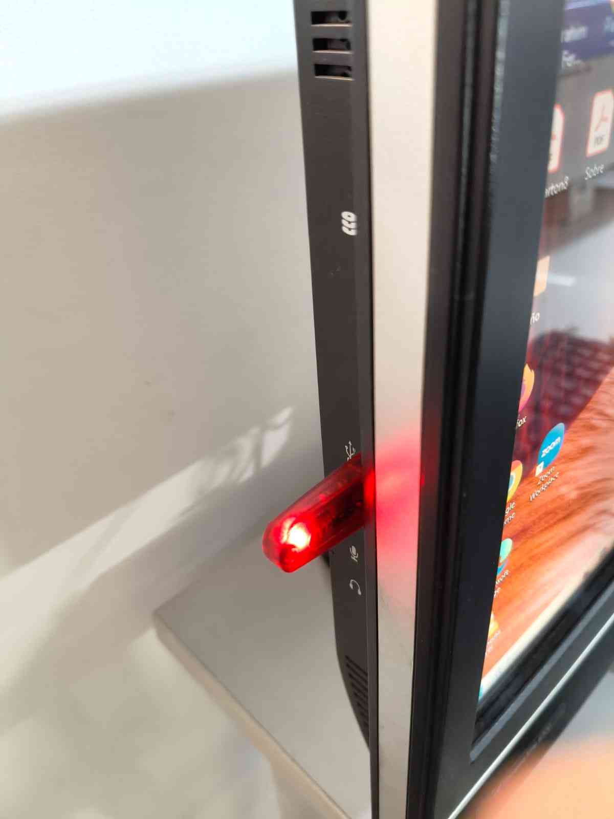
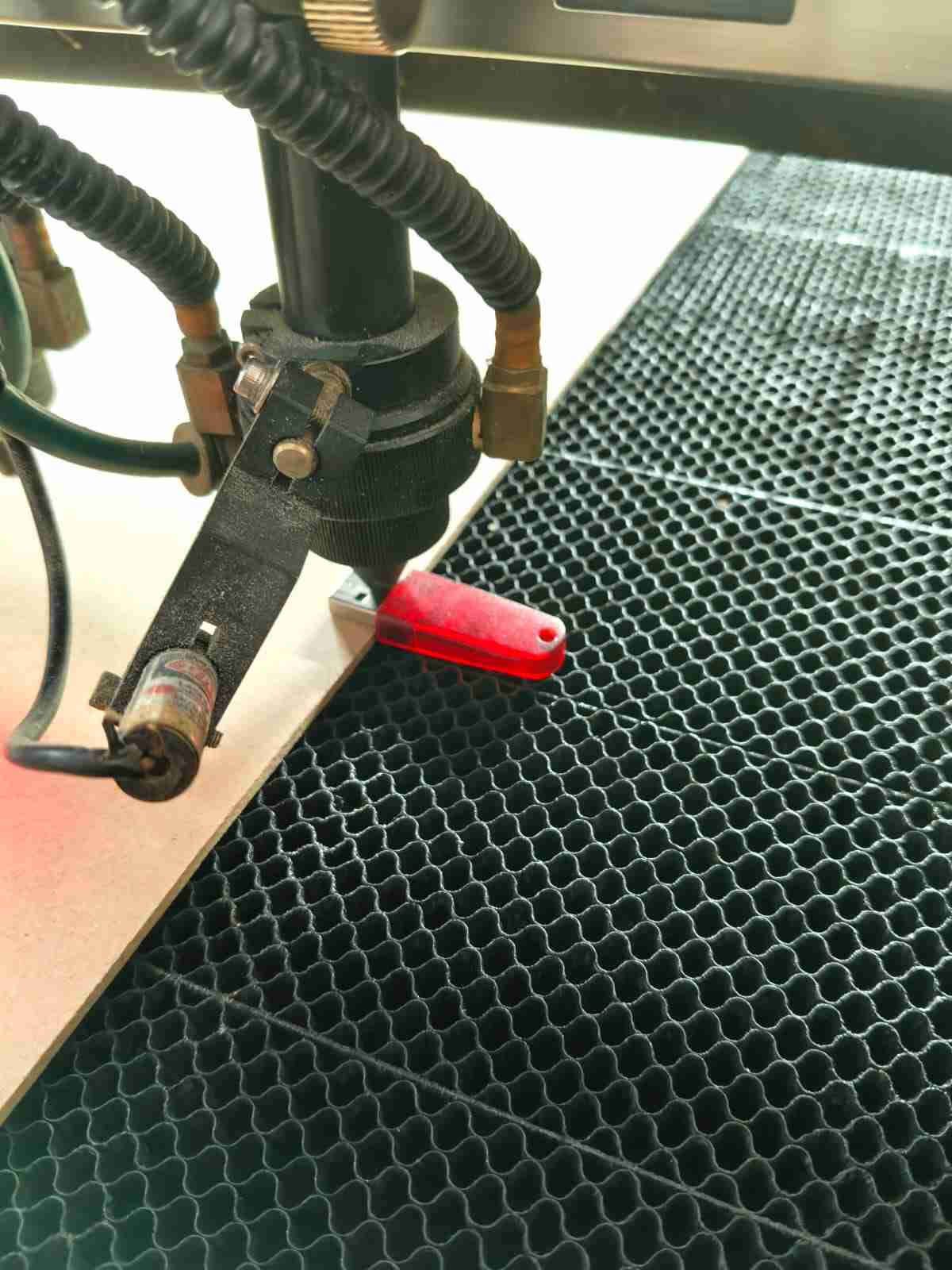
To operate the laser cutter machines present at FabLab Ibero Puebla, one must first ask for permission in advance so the instructors can grant access to the physical and electronic key. The software, which is used for creating the toolpaths, cannot be executed if the computer does not have the red USB with the activation key. At the same time, the machine will only operate if the physical key is inserted in the control panel.
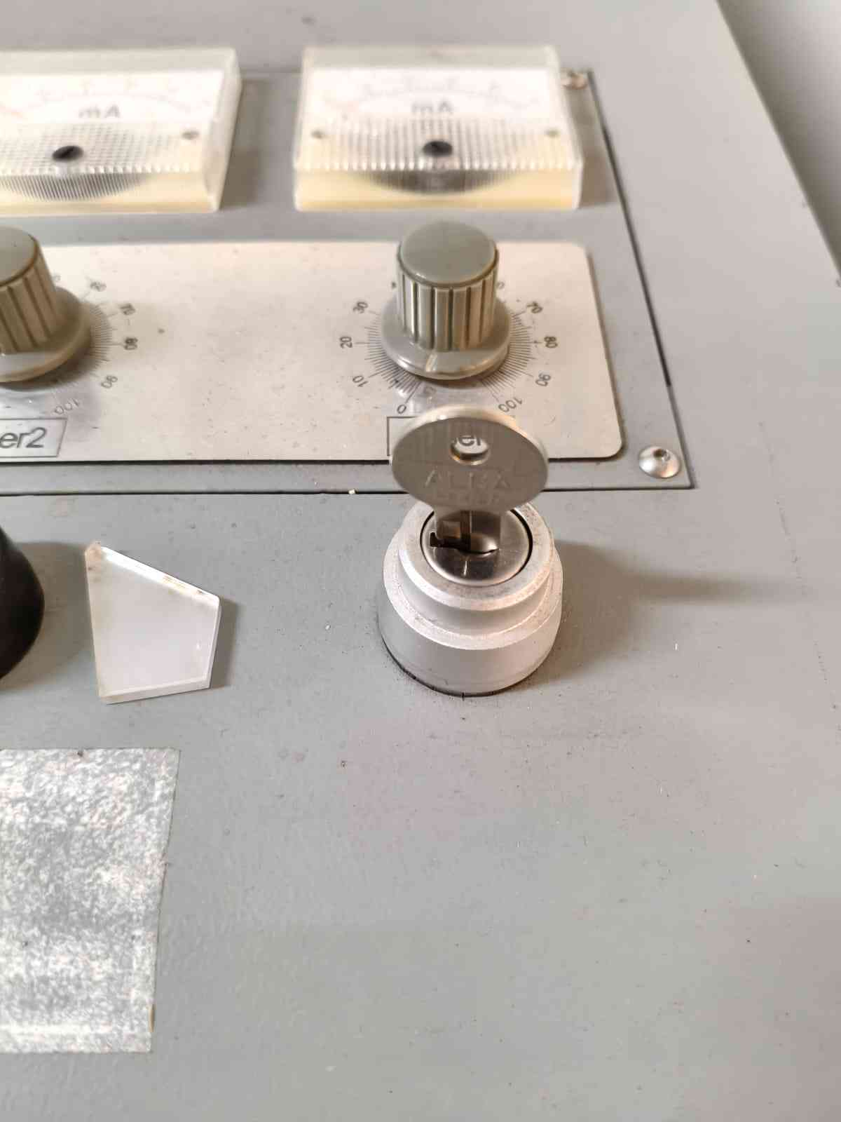
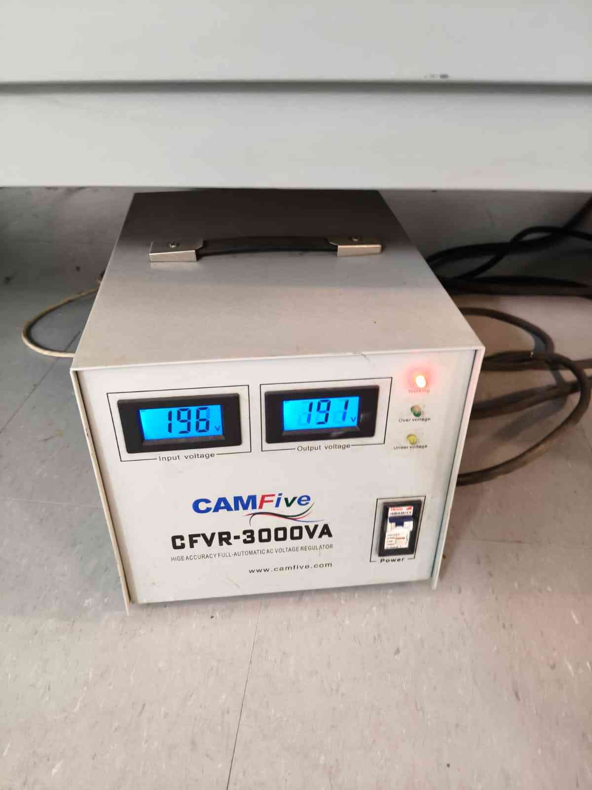
To start the machine, we first have to turn on the power supply and then flip the machine switch. It is easy to tell whenever the machine is running, as its switches have bright red LED indicators.

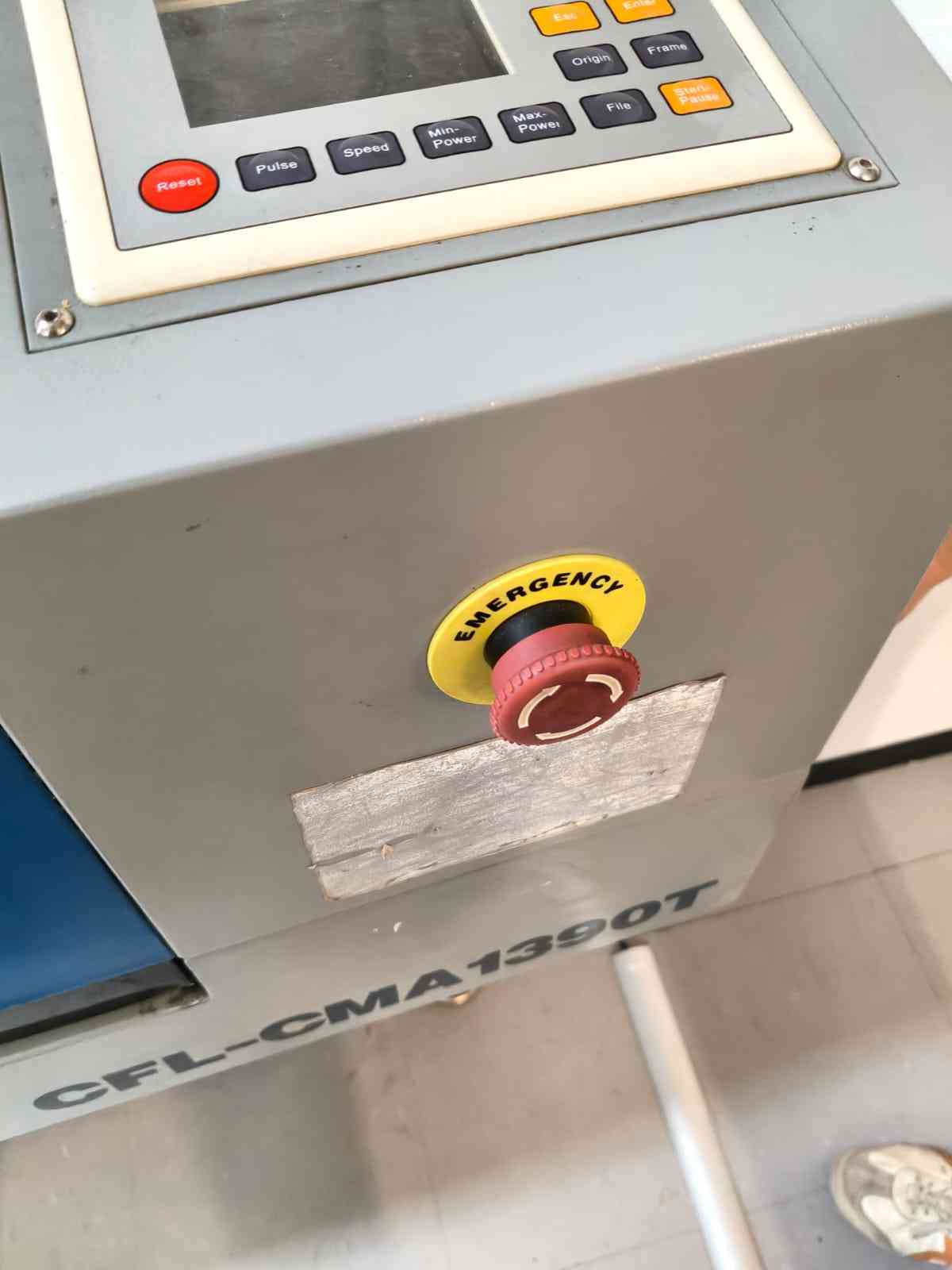
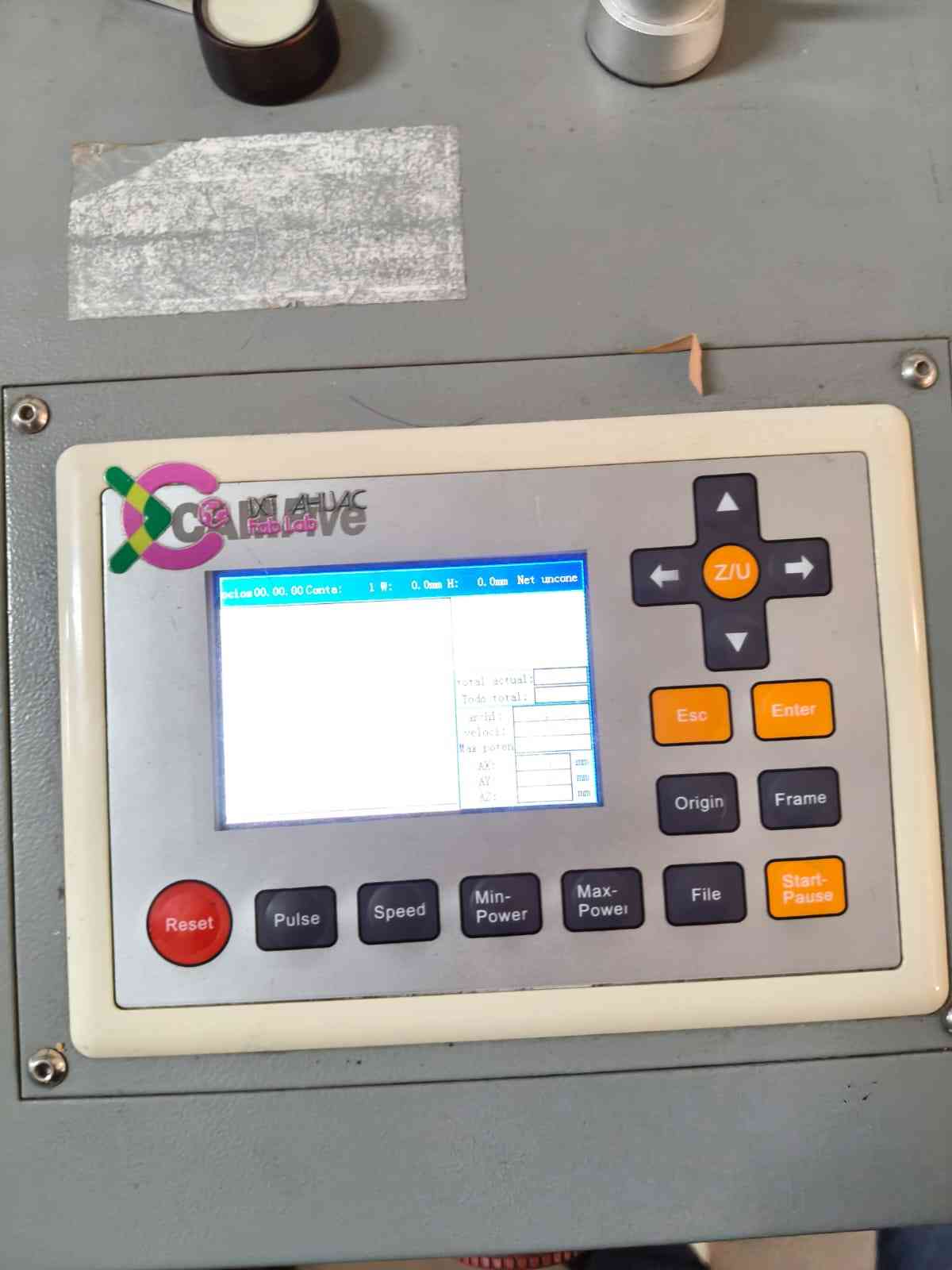
It is crucial to be aware of the emergency stop button and its location before operating the machine. The control panel, situated at the top of the machine, allows for the movement of the laser across the working space, enabling accurate placement of the origin.
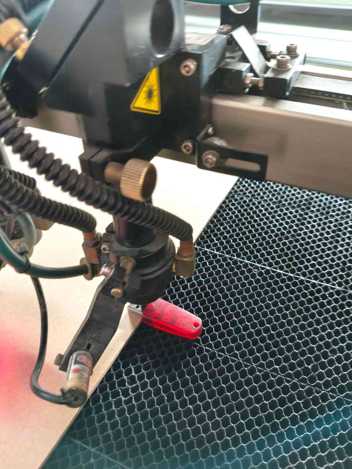
That day, my instructor shared with me an unorthodox approach for zeroing the Z-axis: To use the metallic end of the USB as a reference point. This metallic end is 6 mm tall, which provides an optimal distance for the laser.
With the machine already in position, it was time to get started with SmartCarve, the program that sends the toolpaths to the laser cutter. This program won't work unless the hosting computer has the red USB plugged in.
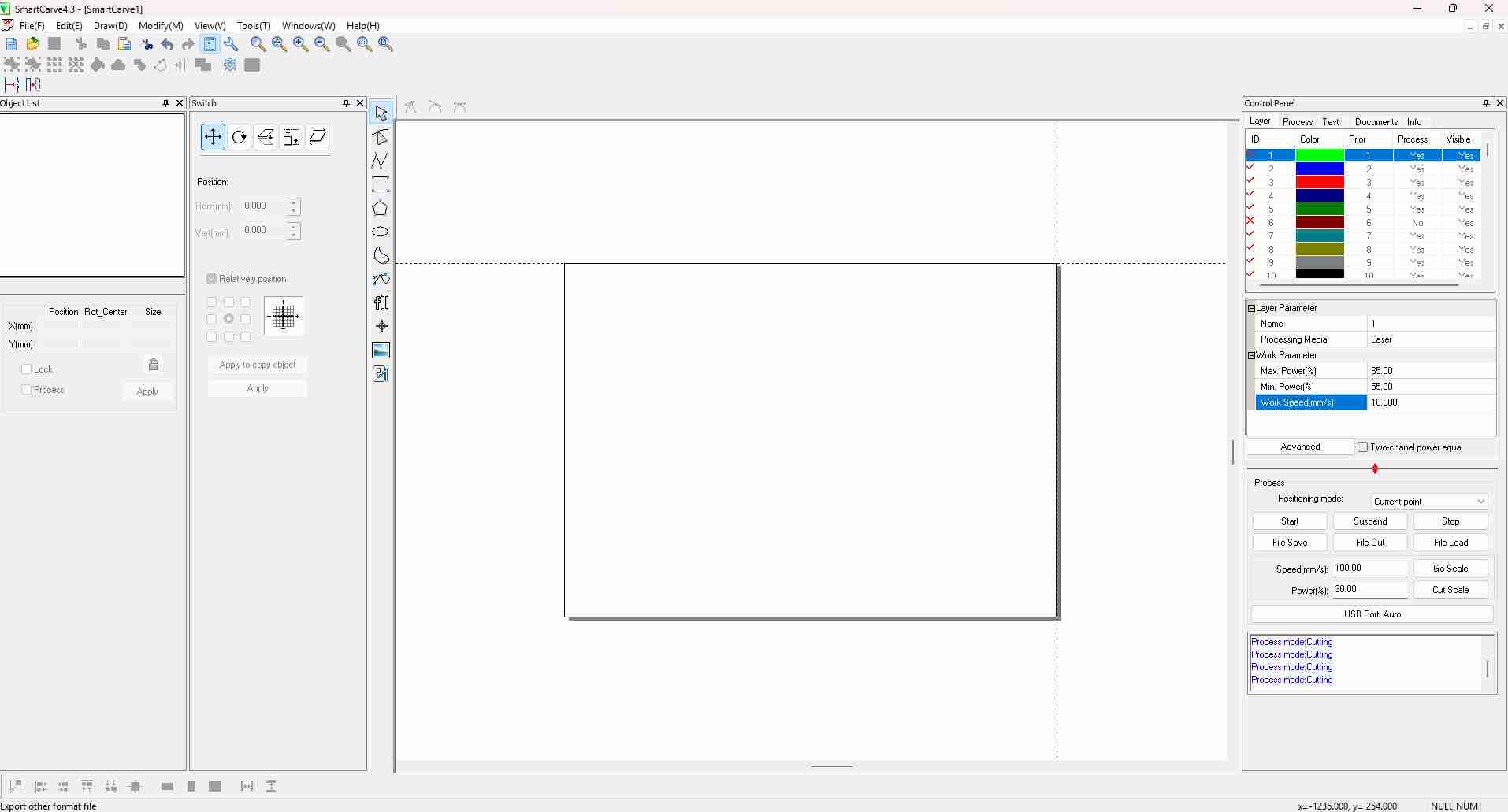
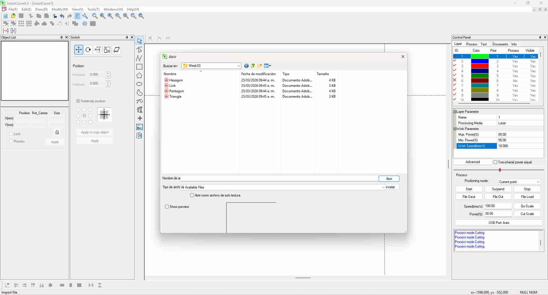
DXF files can be imported by the File menu. DXF files appear as PDF files.
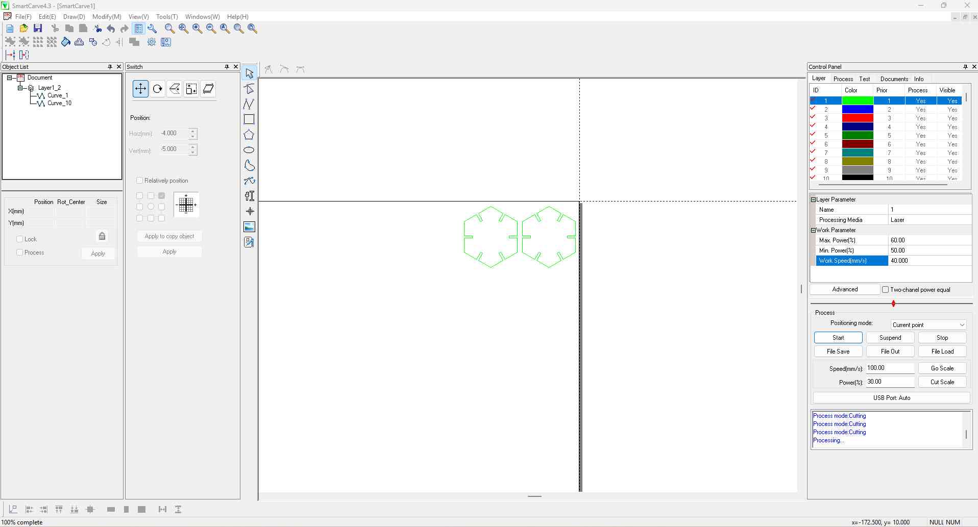
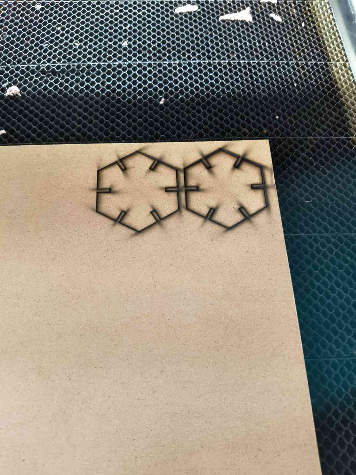
Before committing my MDF sheet to a possibly faulty design, I decided to first send two pentagons to validate the kerf value.
The left section of SmartCarve displays the Object List, which includes all the objects incorporated in the design. This section also features the Control Panel, which sets the cutting parameters for each layer. Layers are processed in a sequential order, meaning that if we choose to utilize all available layers, our design will begin with the green layer and progress through each color until reaching the black layer.
The parameters for the first layer are the following:
- Max. Power %: 60
- Min. Power %: 50
- Work Speed (mm/s): 40
SmartCarve will only send the toolpaths for the selected layers after pressing the "Start" button.
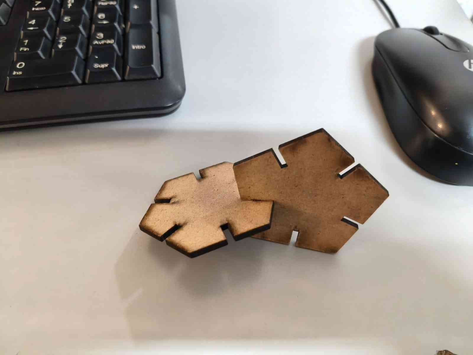
The test pieces could be easily assembled and disassembled for evaluation. This result validated the kerf value and the layer parameters.
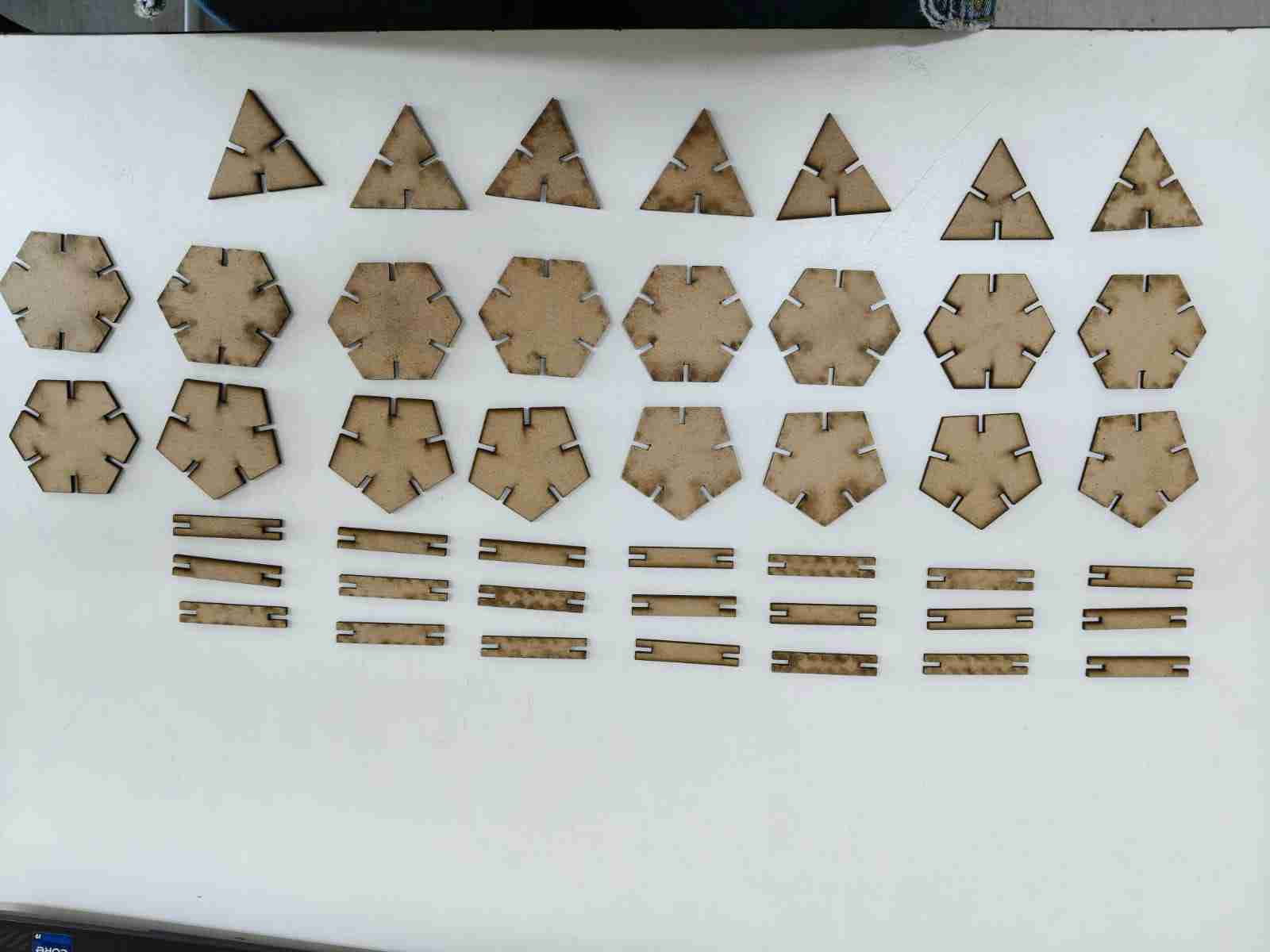
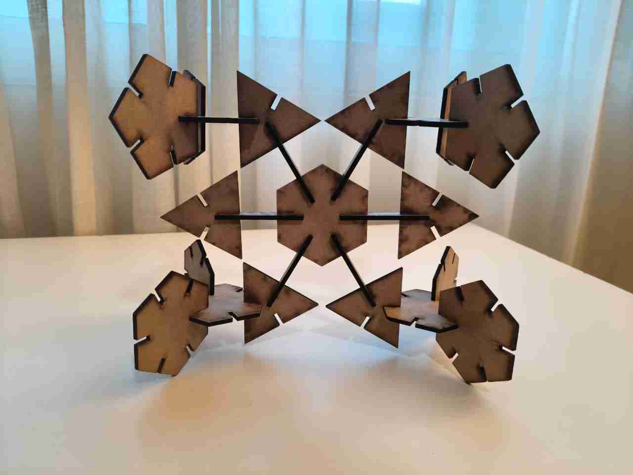
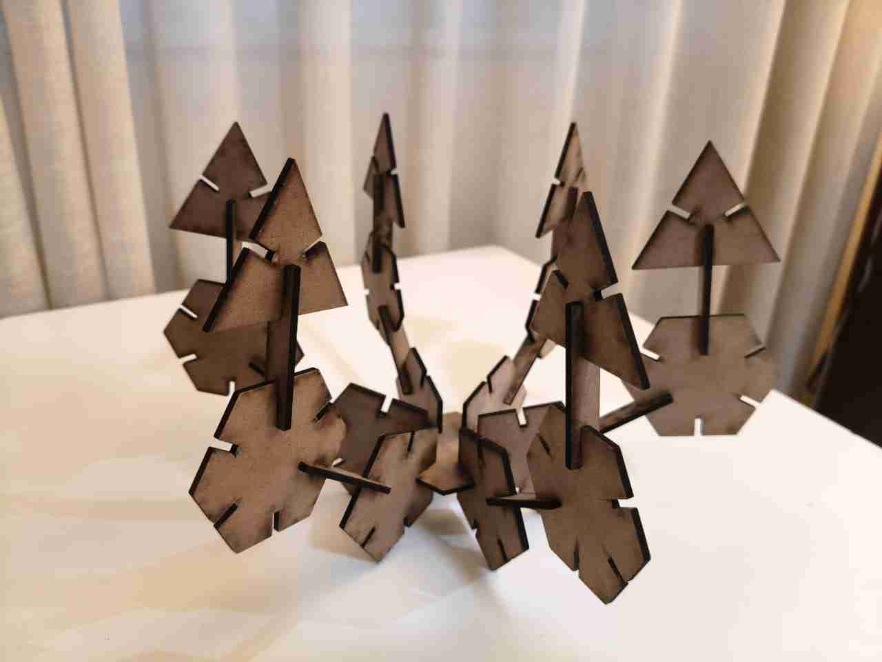
With the parameters validated I then manufactured a batch consisting of 7 triangles, 6 hexagons, 6 pentagons and 21 links.
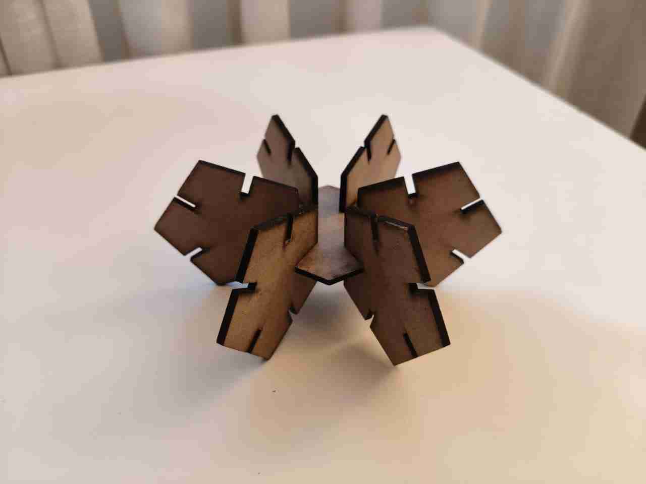
3.1 Assemblies
4. Vinyl Cutter
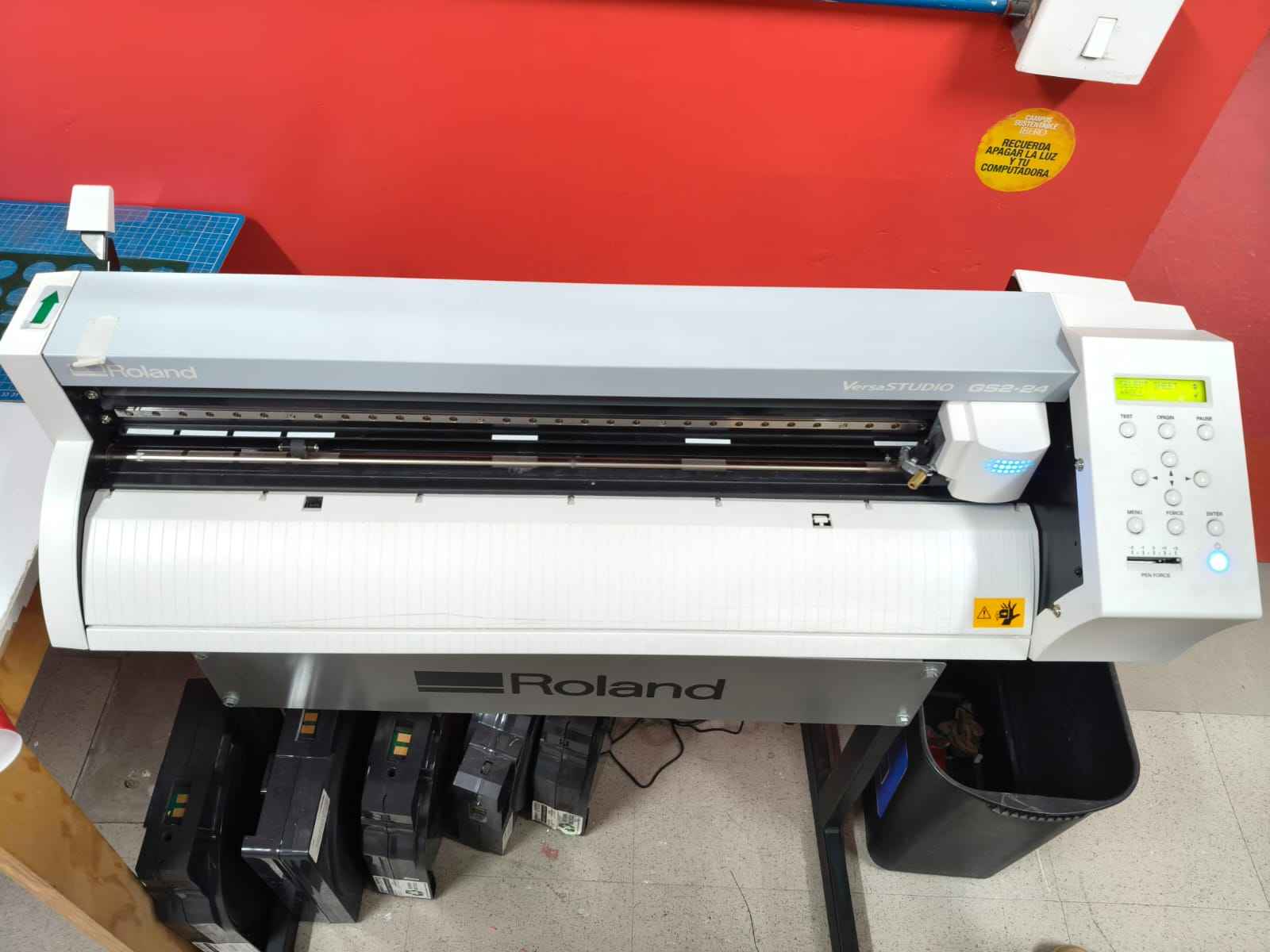
The vinyl cutter I used was the Roland VersaStudio GS2-24. This was not my first choice for the vinyl cutting task, however, because the Brother ScanNCut Mini Plotter was descalibrated and the spray cans for adhering the vinyl were deranged. I had to use the aforementioned machine.
The design I chose for this assignment was the UNSC logo from the Halo universe. The UNSC is one of my favorite organizations from all fiction, and this was my opportunity to finally get some sort of merchandising featuring its logo. As I am attached to my computers, I decided to vinyl cut the UNSC logo in order to add it to my current work computer.
I got the logo from this website: UNSC logo
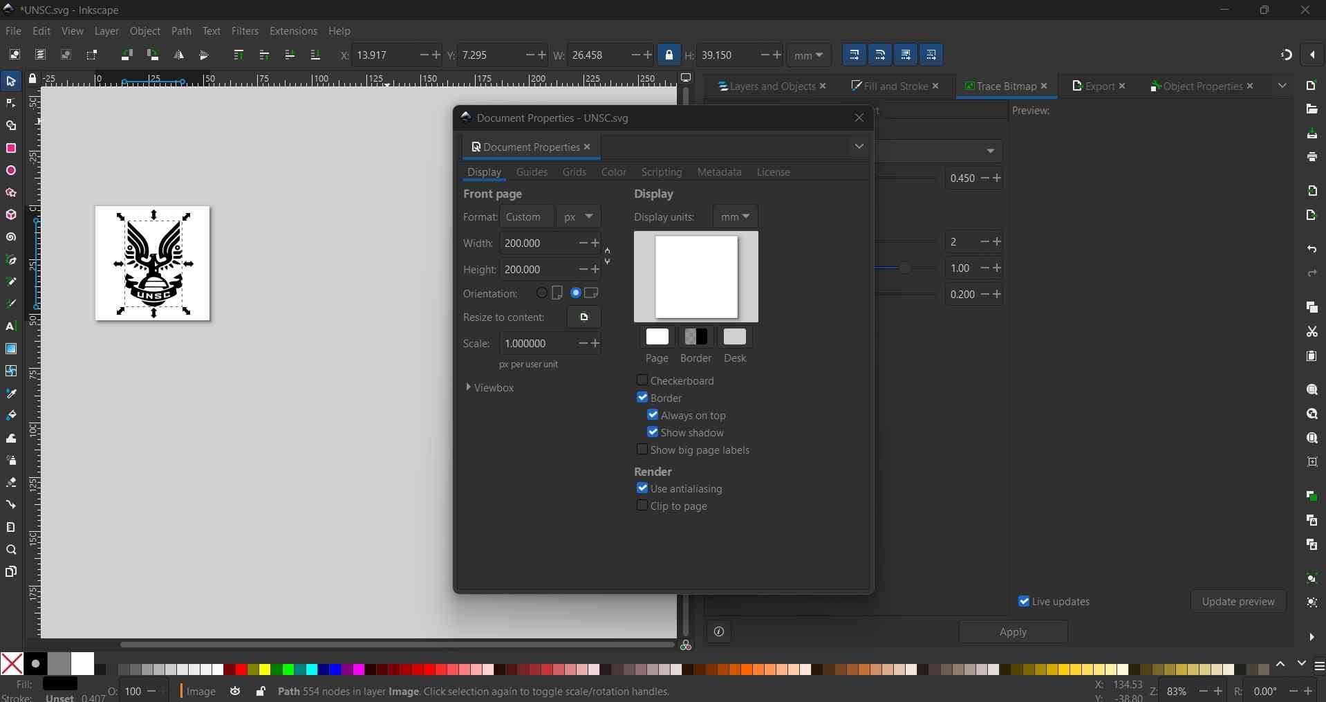
After downloaging the image, I proceeded to vectorize this image in inkscape, this step ensures that the image can be cut with precision.
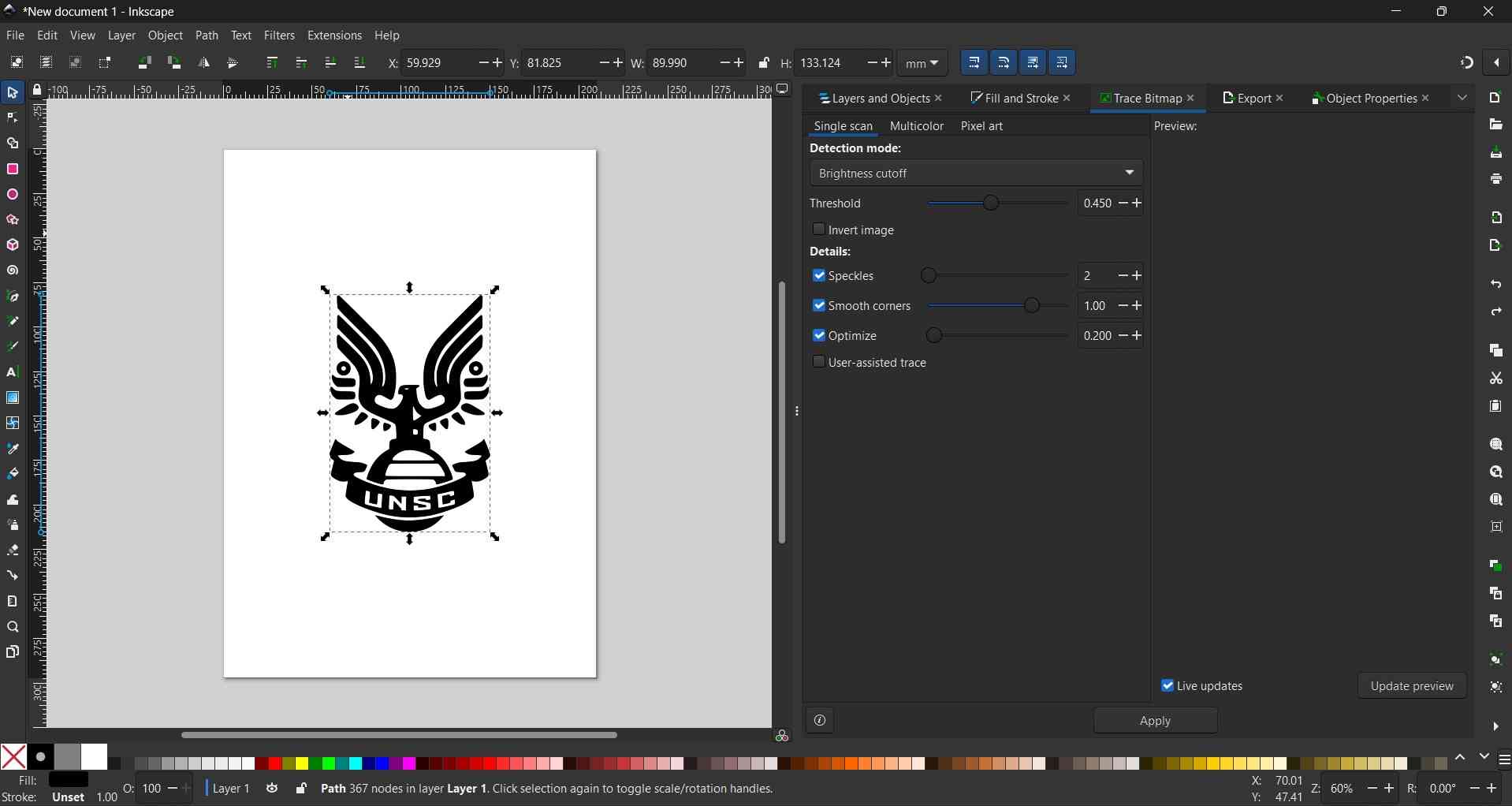
Side by side comparison of the original and vectorized images, the original seems fuzzy, while the vector looks sharp:
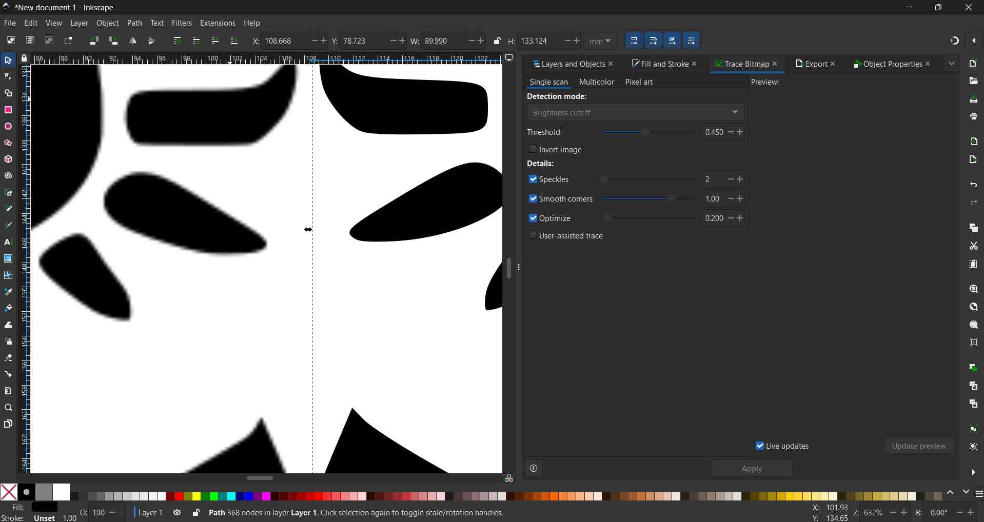
With the image vectorized, the next step is to adjust the workspace area. After this adjustment, we can now save our file as an SVG.
To prepare the toolpaths for the vinyl cutter, we need to access a computer with the CutStudio software installed.
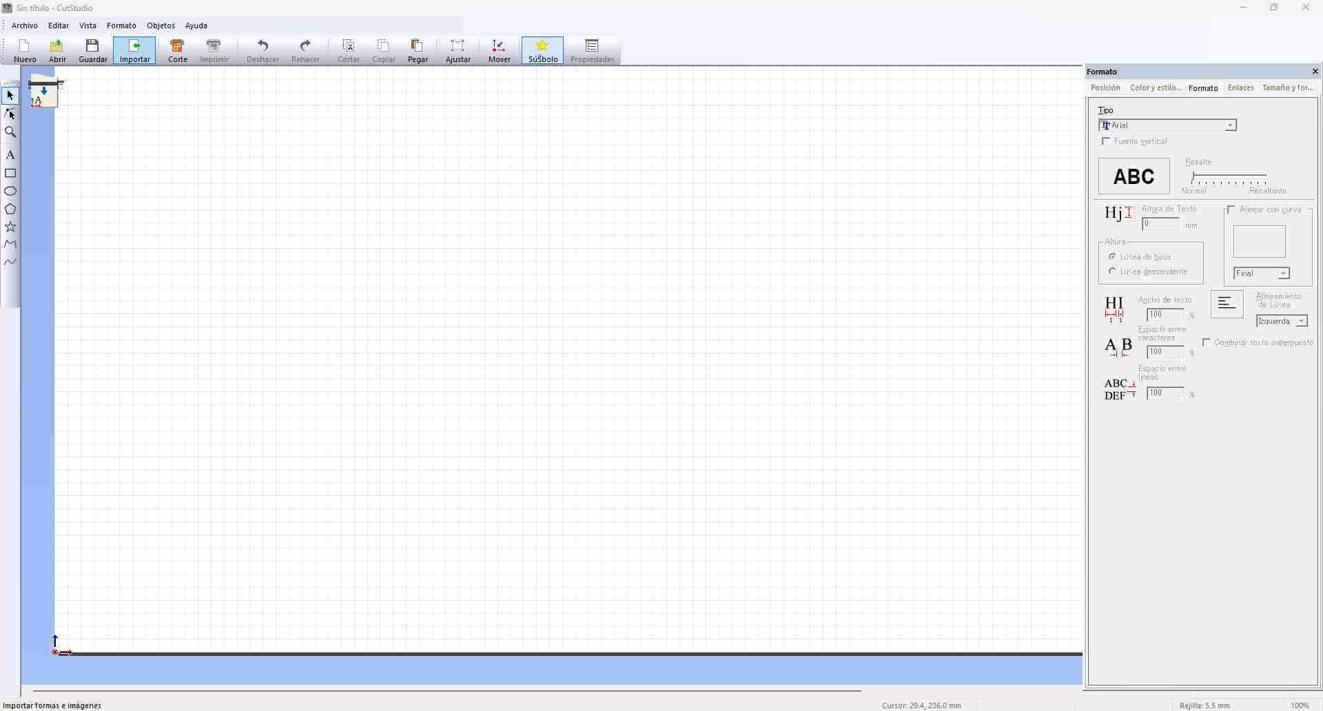
The first step towards creating the toolpaths is to import the vectorized image into the software.
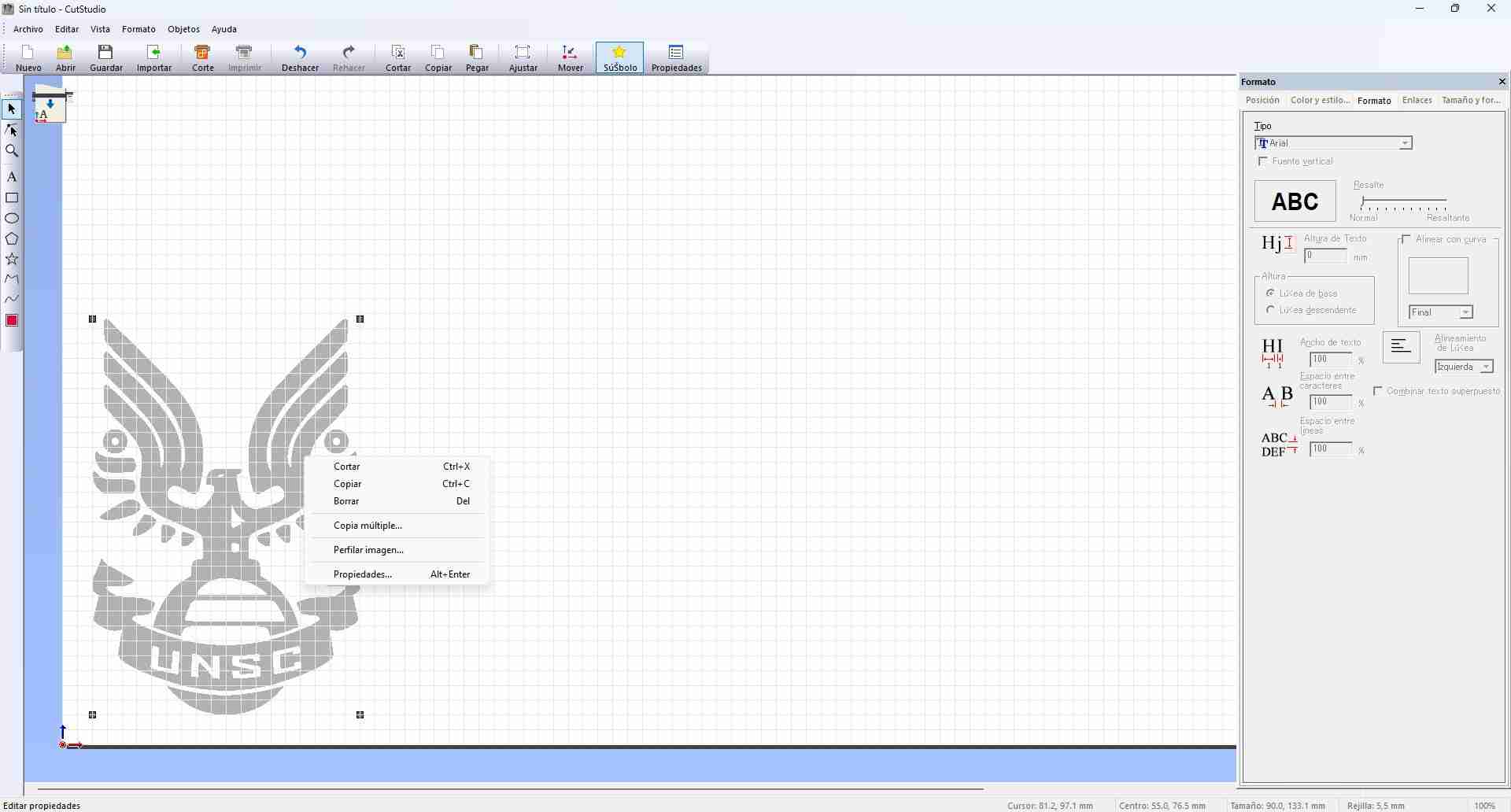
Imported images must be profiled to create the toolpaths for cutting.
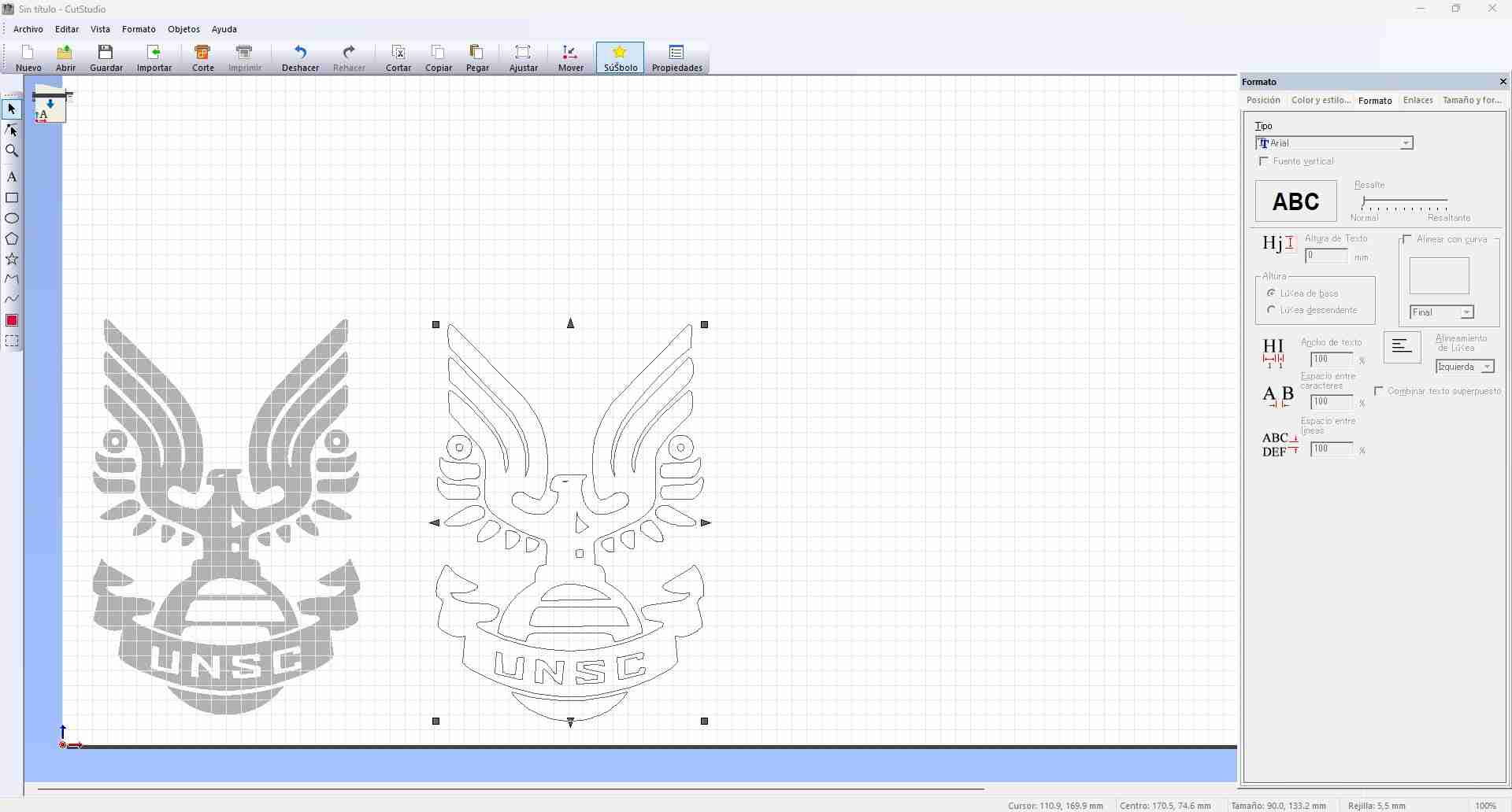
After profiling, the toolpaths can be generated for the vynil cutter by pressing the button Cut at the top of the main window.
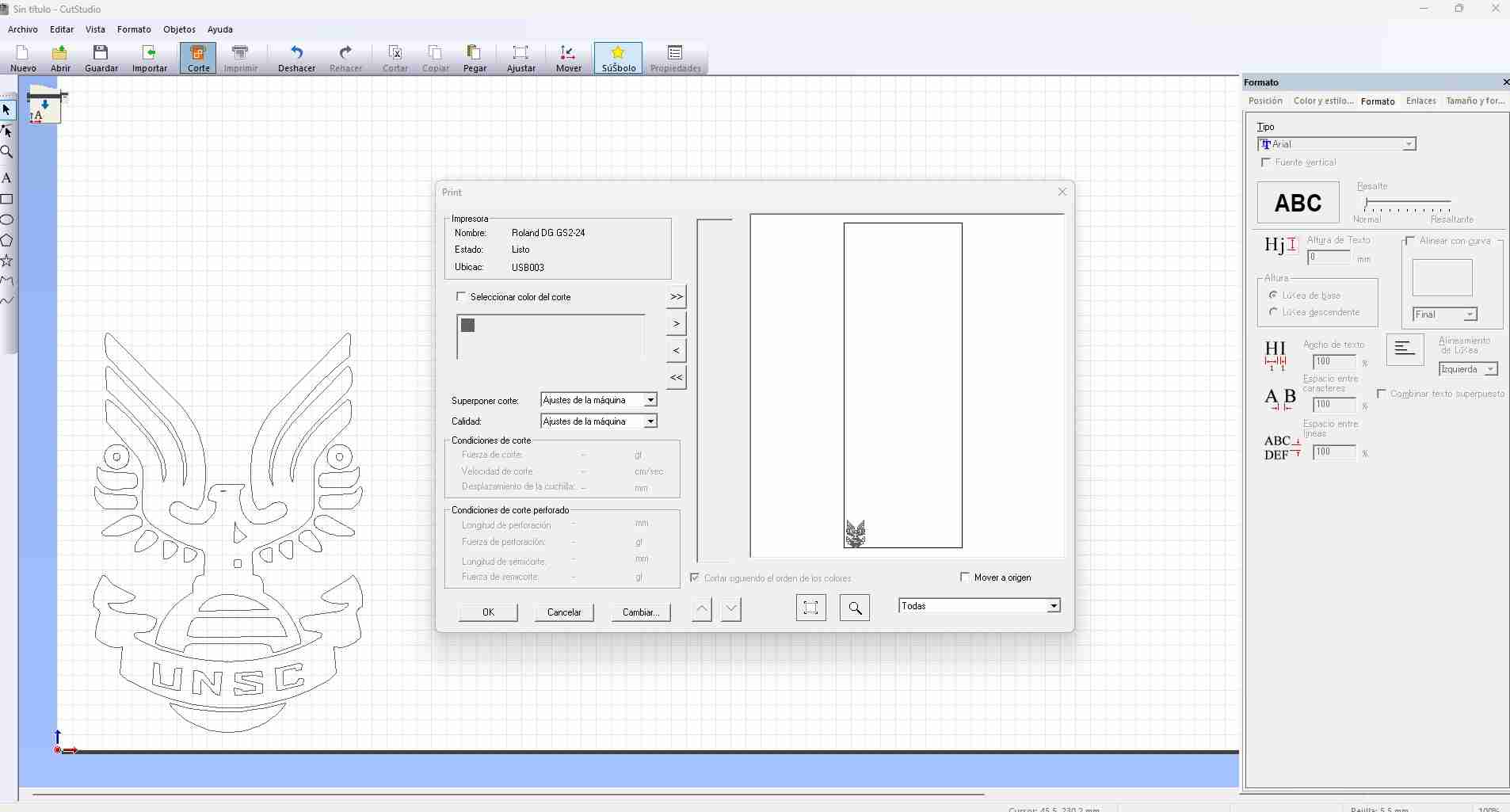
With the toolpaths generated, we can now insert our vinyl in the machine and establish the origin point using the control panel present at the vinyl cutter.
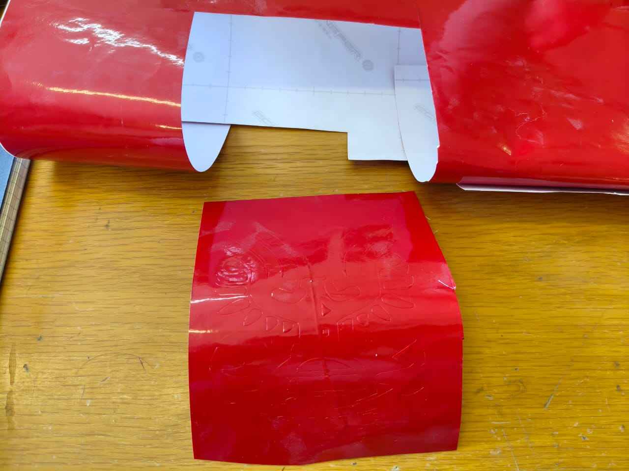
After the cutting process is completed, we can now remove our design from the vinyl cutter to start the post-processing, which involves removing the excess material.
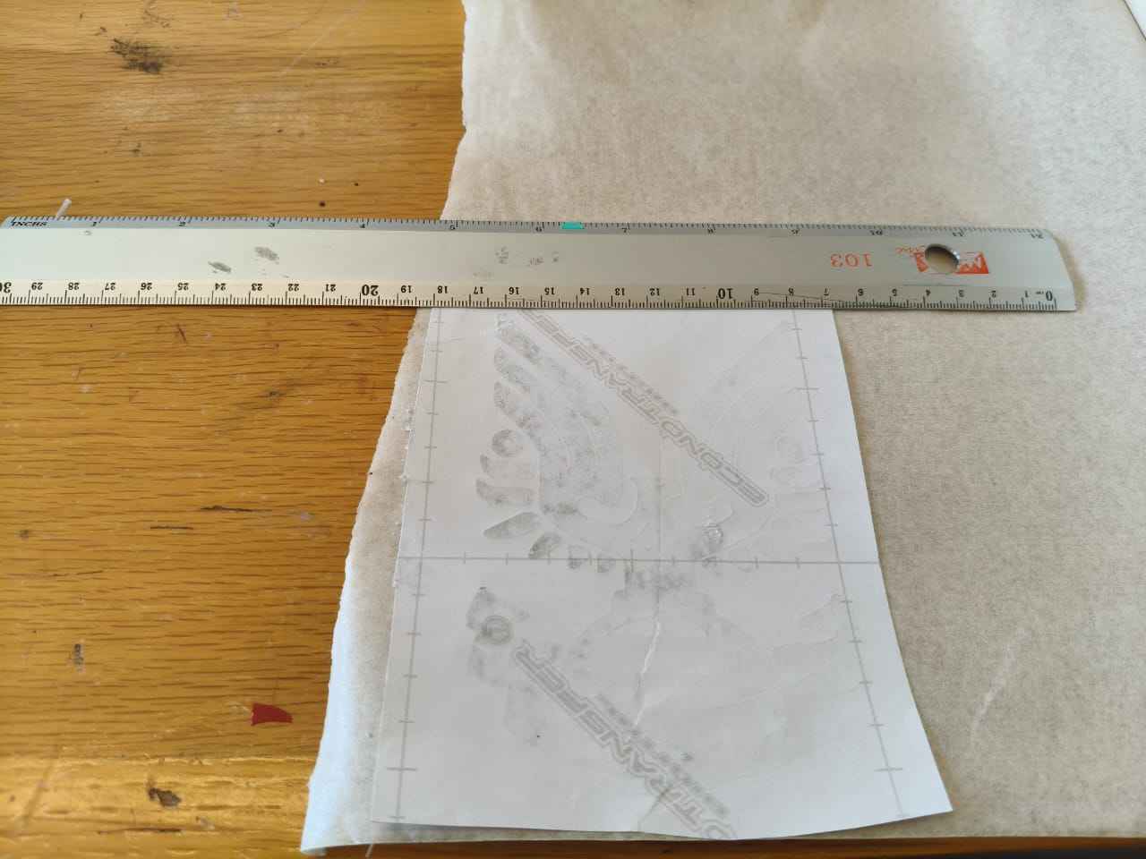
After removing any excess material, we can proceed with adhering the front of the design to the transfer paper.
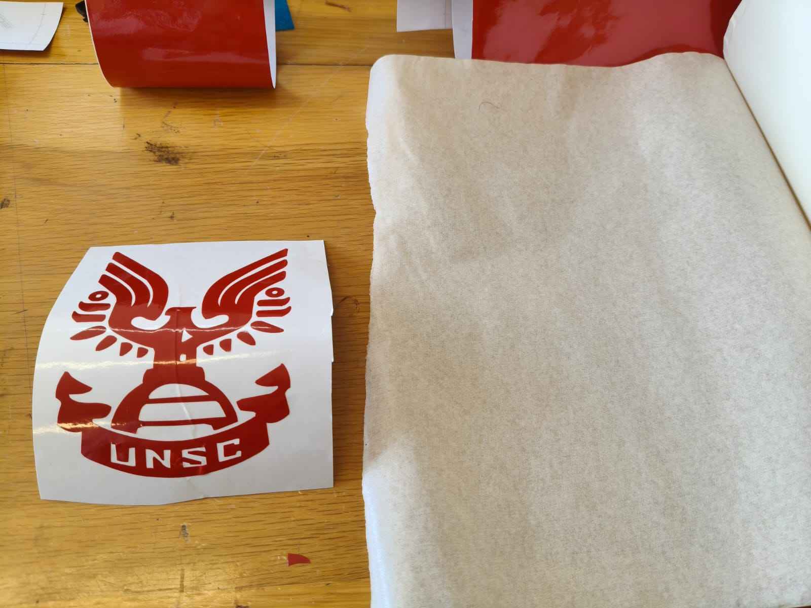
I used a ruler to ensure proper adhesion.
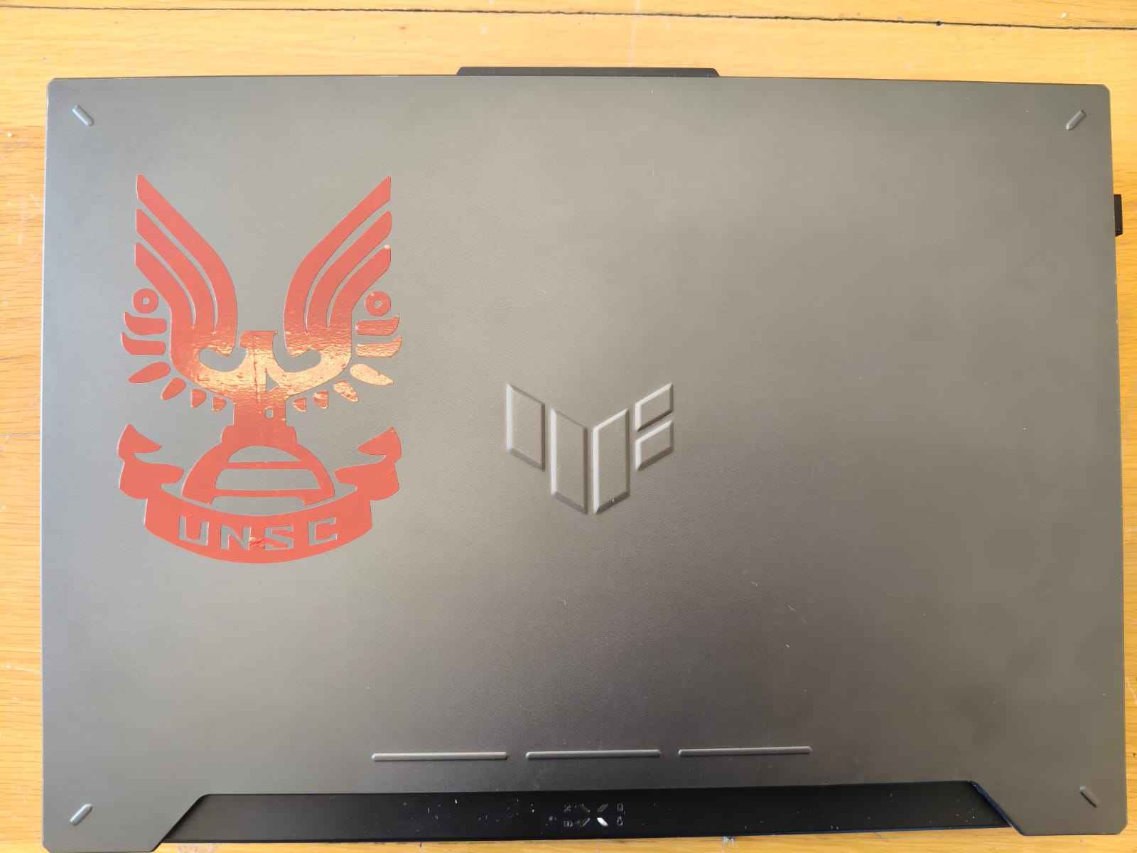
And this was my final result, I can now say that my laptop is issued by the UNSC, ready to fight the Covenant!
4. Files
Here are the downloadable files for this week:
Fusion 360 Files, DXF files and SVG3) Reflection
This was my first time working with machines that were bigger than me, and I must say, I was nervous at first. Fortunately, my instructors guided me through the whole process and answered each and any questions I had. As for the design of the parametric kit, the trickiest part for me was adding the laser kerf. I did not know how to interpret it at first, but I was able to add it into my parameters in the end, which was the defining factor in ensuring my assemblies held together. Regarding the vinyl cutting machine, I agree with Neil's assessment; it is indeed the most underrated machine in the FabLab.