PRUEBA DE CAMBIO 123
Group Assignment
Characterize the CNC machine by testing runout, alignment, speeds, feeds, and toolpath types to understand its specific capabilities and tolerances.
Group PagePlanning
The idea came up because I am moving to a new house and the space where I live is small. I also don't have an outlet nearby, a nightstand, or a bedside lamp. So the intention for this week was to create a piece of furniture that could cover all those needs.
The initial ideas were the following:
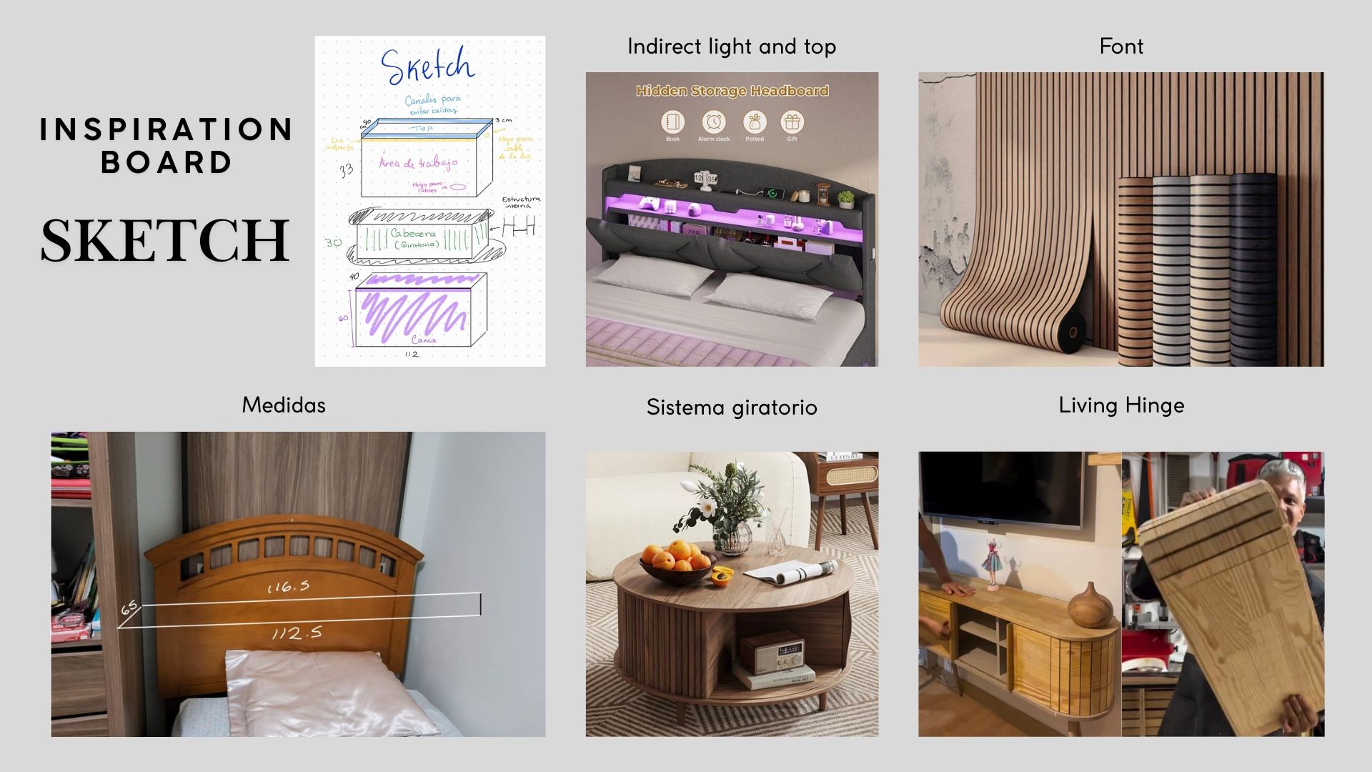
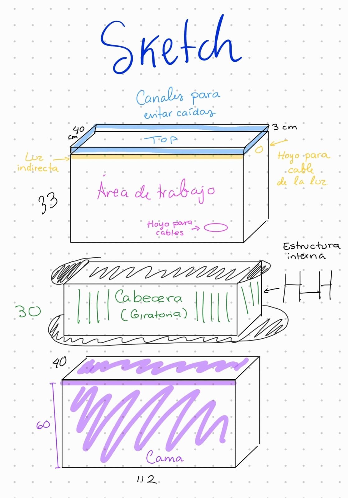
On the other hand, I believe that a large part of whether a project succeeds or not depends on its planning. Therefore, it was necessary to create a sketch with the components of my design.
Solid Works Design
Once the design was planned, I proceeded with the 3D modeling in SolidWorks. Below, I present the engineering drawings for each part of the design, as well as a 3D view showing the full assembly.
My SolidWorks design.
Assembly
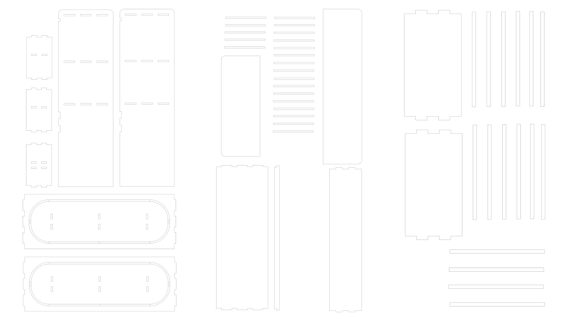
Vector Design
Software

VCarve
VCarve - Software for creating decorative carvings on CNC machines
VCarve lets you design and create stunning 2D and 3D decorative carvings, ideal for artistic and personalized projects in wood and other materials.

Aspire
Materials used
- Plywood 122 cm x 240 cm, 12 mm thick
- Endmill bit 1/4"
Using the software
The software I used was VCarve Pro, since our university has the license.
Note: When designing the pieces it is important to do so with zero tolerance, since the tolerances (the "kerf") will be calculated automatically by the software.
In the left panel, the following steps are performed:
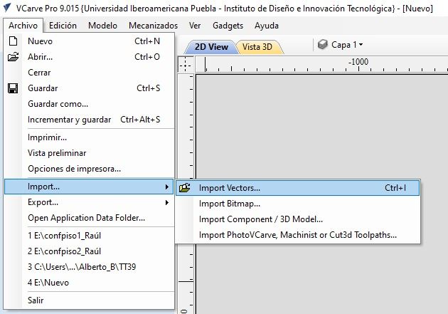
First step
- Open a new file and import the vector document (i.e., the DXF file from the SolidWorks drawing).
Second step
- Enter the material dimensions in millimeters in the software. These measurements are only used as a reference to avoid going beyond the physical material.
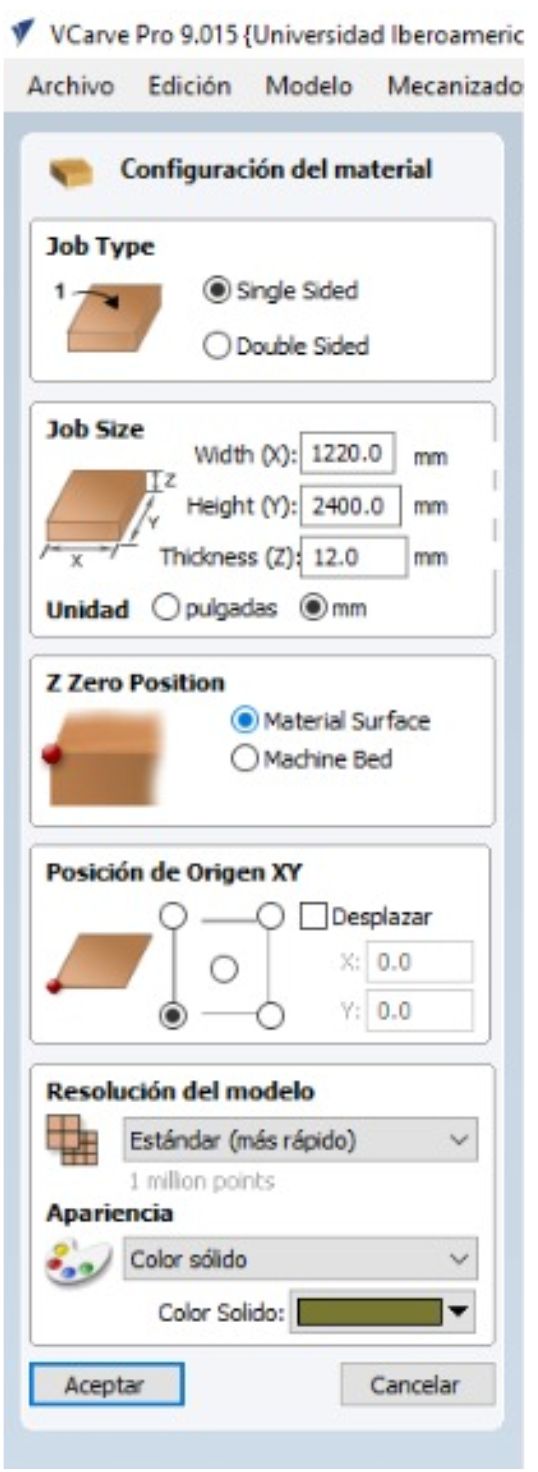
Mistake I made: In this case, I set the material in horizontal orientation, which is incorrect since the machine bed is vertical — this can cause errors. Please note that the screenshots shown below were taken with the material set horizontally; however, I later corrected it to vertical and repeated the entire process shown here.
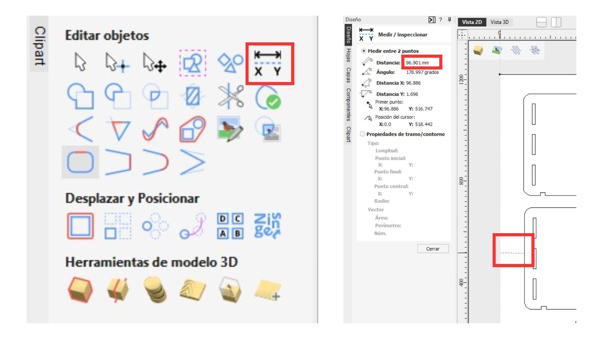
Third step
- Using the "Measure" tool, I verified that the space between all pieces and the edge is greater than 19 mm (which is three times the diameter of my 1/4" bit).
Note: Clamps will be placed in the corners of the work area, so nothing should be placed there.
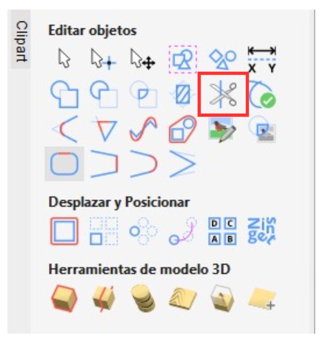
Fourth step
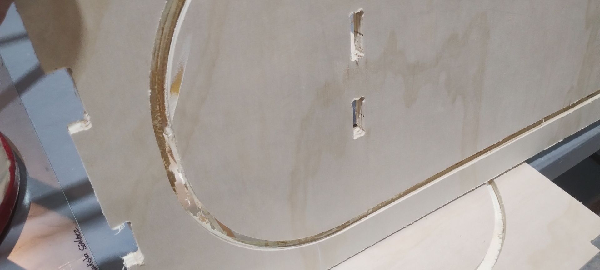
- Using the trim tool, the lines of the ovals that will serve as the furniture's rails are removed, so the software does not interpret them as cuts.
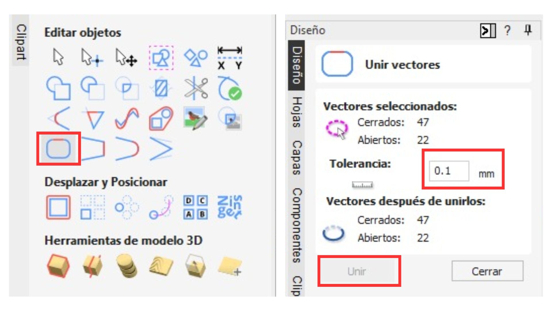
Fifth step
- Then all pieces are selected and the "Join Vectors" button is clicked.
Sixth step
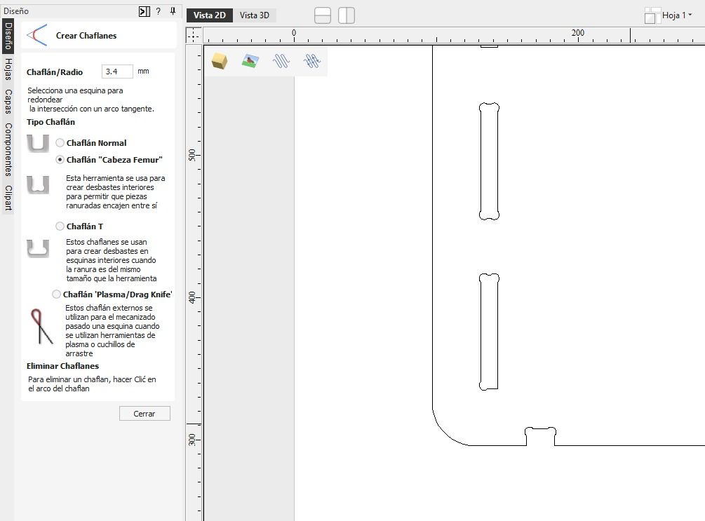
- Next, the "Fillet" option is applied to create a rounded corner on all female (internal) joints in the piece, to prevent the CNC from curving the material removal and blocking the correct fit with its counterpart.
Making a cut
Next, we move to the right panel in the software to configure the cut parameters.
- Select all the cuts by holding "Shift" and clicking on each shape.
- Select the "Profile" option to perform the cut.
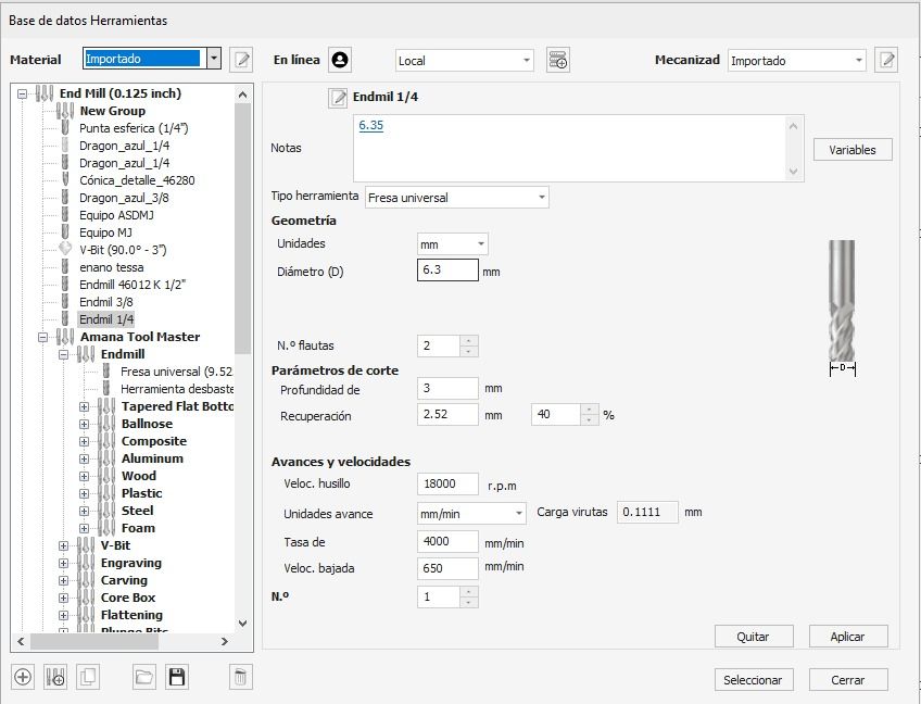
- In the panel that opens on the right, click "Select" in the tool section.
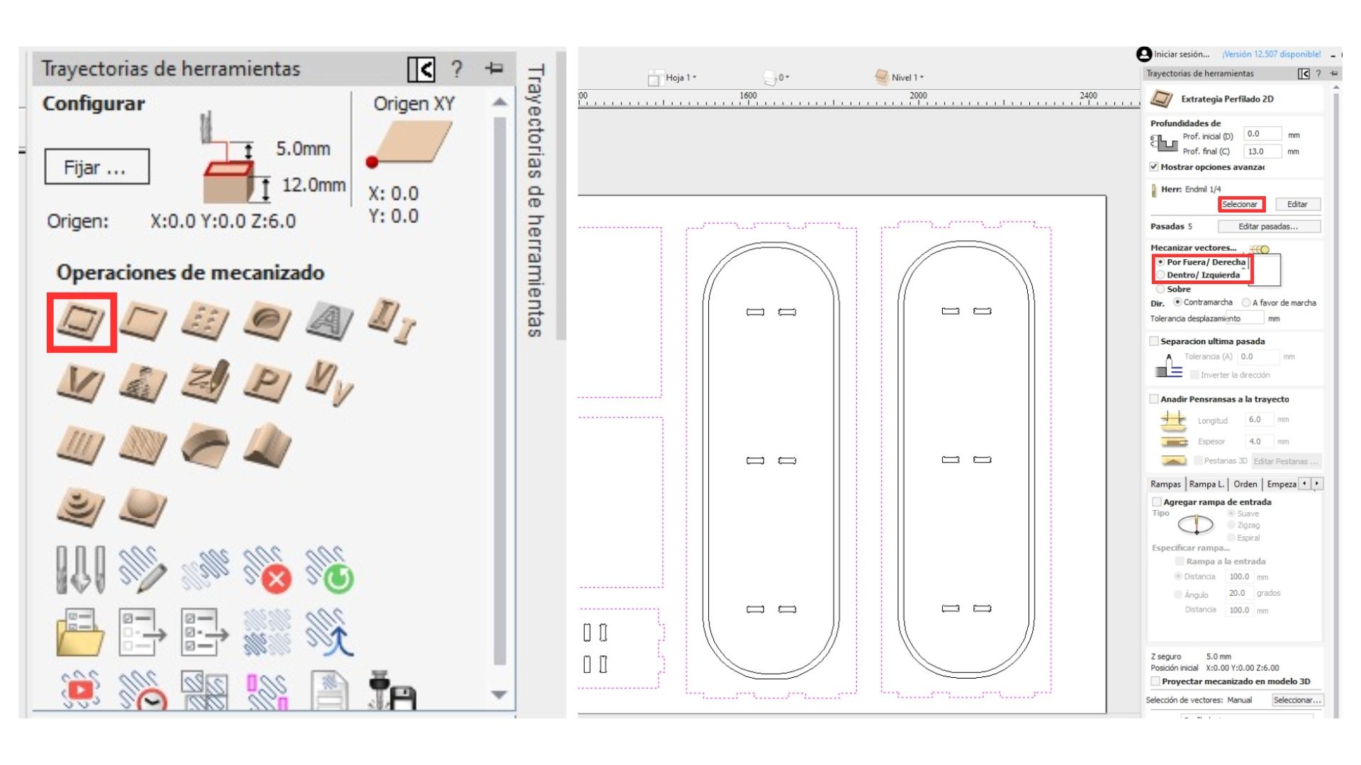
Note: There are three types of cuts (the kerf is calculated automatically):
- Outside: Passes outside the line; used for all male pieces and external cuts.
- Inside: Used for female joint pieces.
- On: Cuts directly on the line; mainly used for engravings.
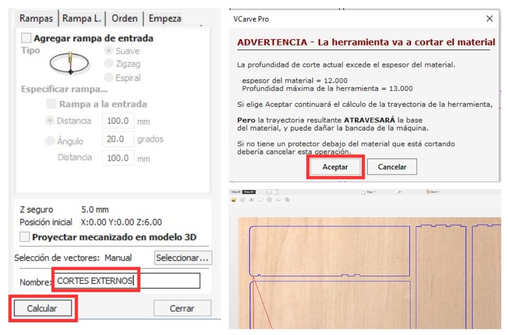
Cut parameters used
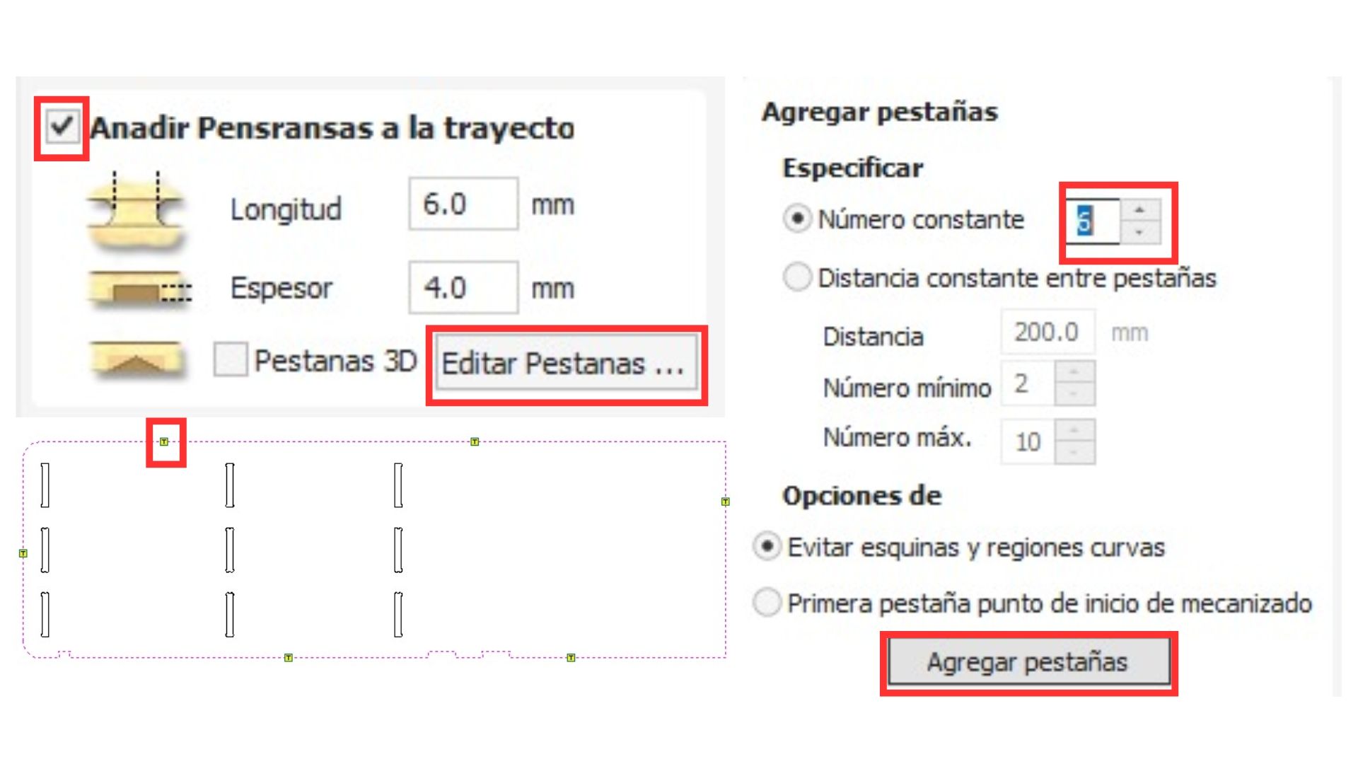
- Check the "Add tabs to toolpath" checkbox to add tabs that will hold the pieces in place and prevent them from flying off. Set the tab size — the one that has worked well is 6 mm x 4 mm.
- Click "Edit Tabs" to let the system place them automatically, then adjust their positions as needed.
Note: Tabs should not be placed in hard-to-reach areas for the machine, such as the corners of pieces.
- Finally, give the layer a name with the parameters you set, then click "Calculate". A warning will appear saying that the cut depth exceeds the material thickness — this is fine, just ignore it. A "3D" tab will open where you can preview how the cut will look.
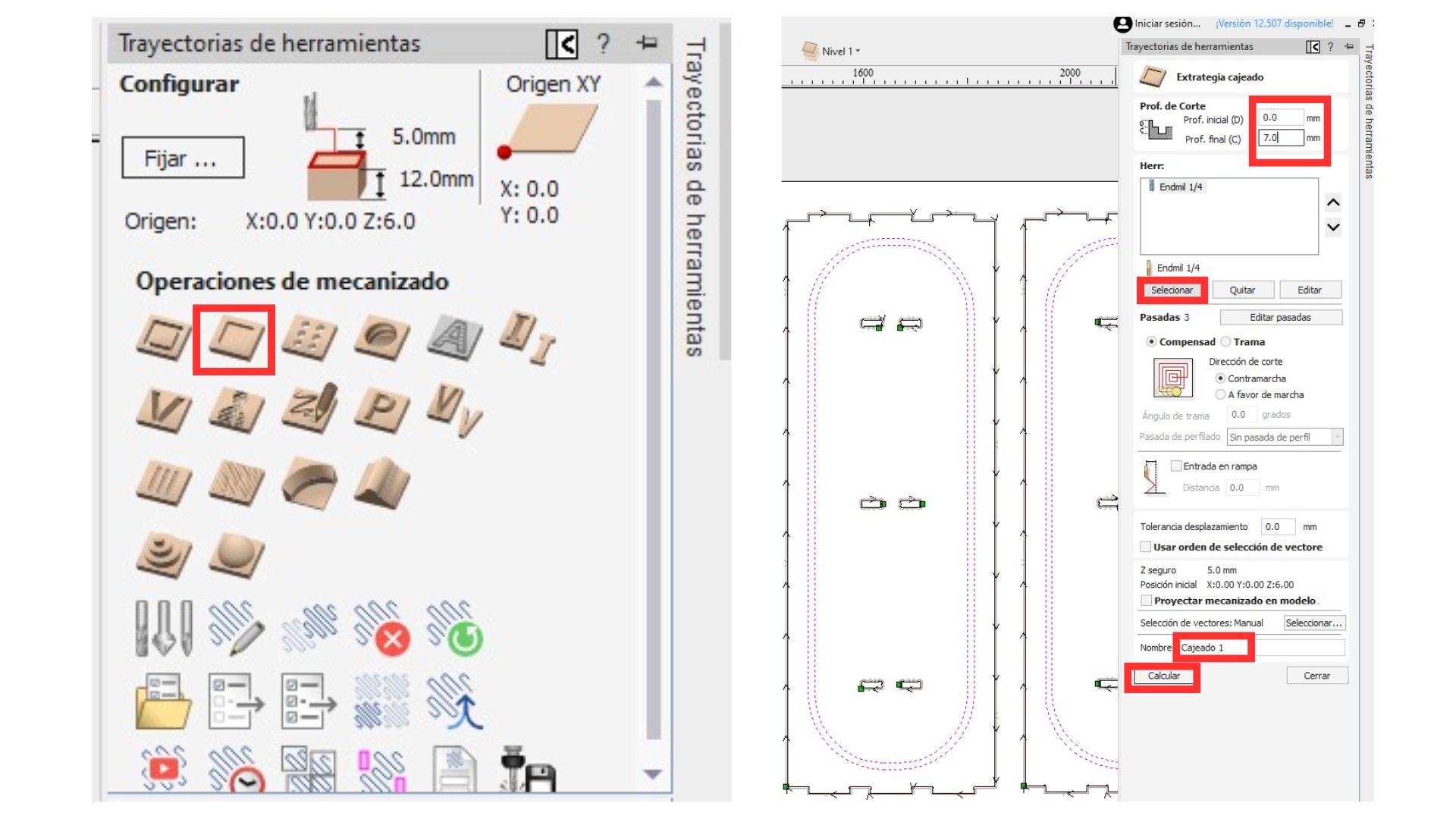
Pocketing
In the same right panel under the "2D" section, the following steps are performed:
- Select the pieces using "Shift" and clicking on them.
- Select the "Pocket" option from the menu to create the furniture's rail slots.
- Set the desired pocket depth.
- Select the same tool and configuration used for the cut.
- Give the toolpath a name and click "Calculate".
Toolpath simulation
It is possible to simulate the CNC path. To do so, simply:
- Click "Preview Toolpaths".
- Click "Simulate All Toolpaths".
- Click the play button to start.
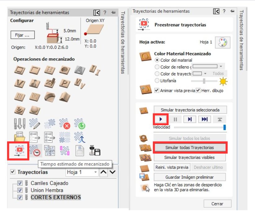
Time estimation
Click the "Estimated Time" option to see the total machining time. All toolpaths must be selected.
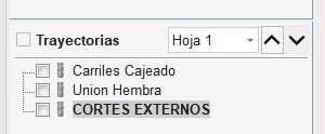
Layer organization
It is vital to organize the layers in the following order:
- Engravings
- Small cuts such as female joints
- Large external cuts
Saving the file
- Click on "Save Toolpath".
- The available save formats are:
- Red CNC: Mach 2/3 Arcs (mm) (*.txt)
- Black CNC: Asia Robotics
- The toolpath(s) must be saved in G-Code format.

Note: Export in both formats so you can cut on either machine.
Cut
Safety considerations
- Lab coat
- Safety boots
- Safety glasses
- Noise-cancelling headphones
- Face mask to avoid inhaling residues
- Hair tied back
Materials
- Face mask
- Safety boots
- Lab coat or overalls
- 12 mm plywood
- Nails
- Hammer
- Rubber mallet
- Safety glasses
Cutting steps
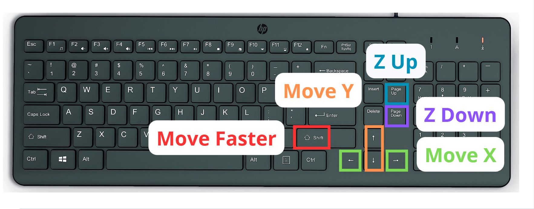
Before using the software, it is important to know the following keyboard commands. Remember that pressing Shift + the desired axis key will move it faster.
Cutting Process
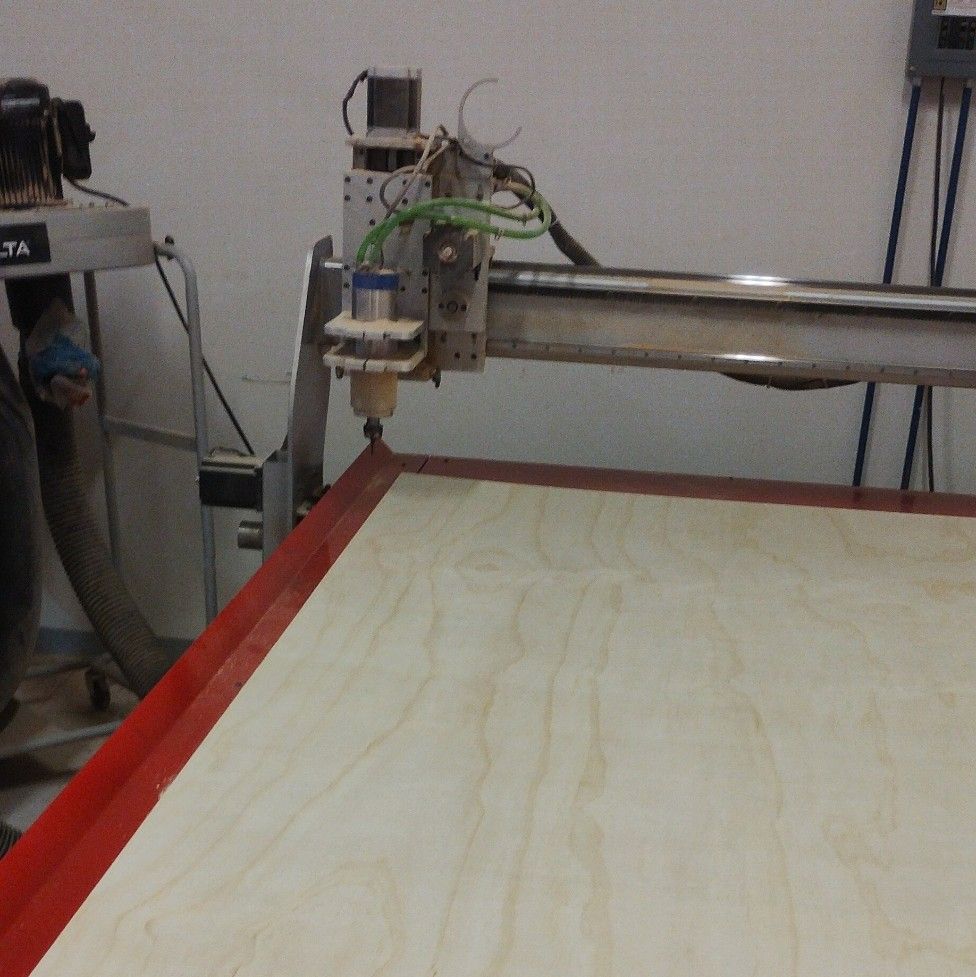
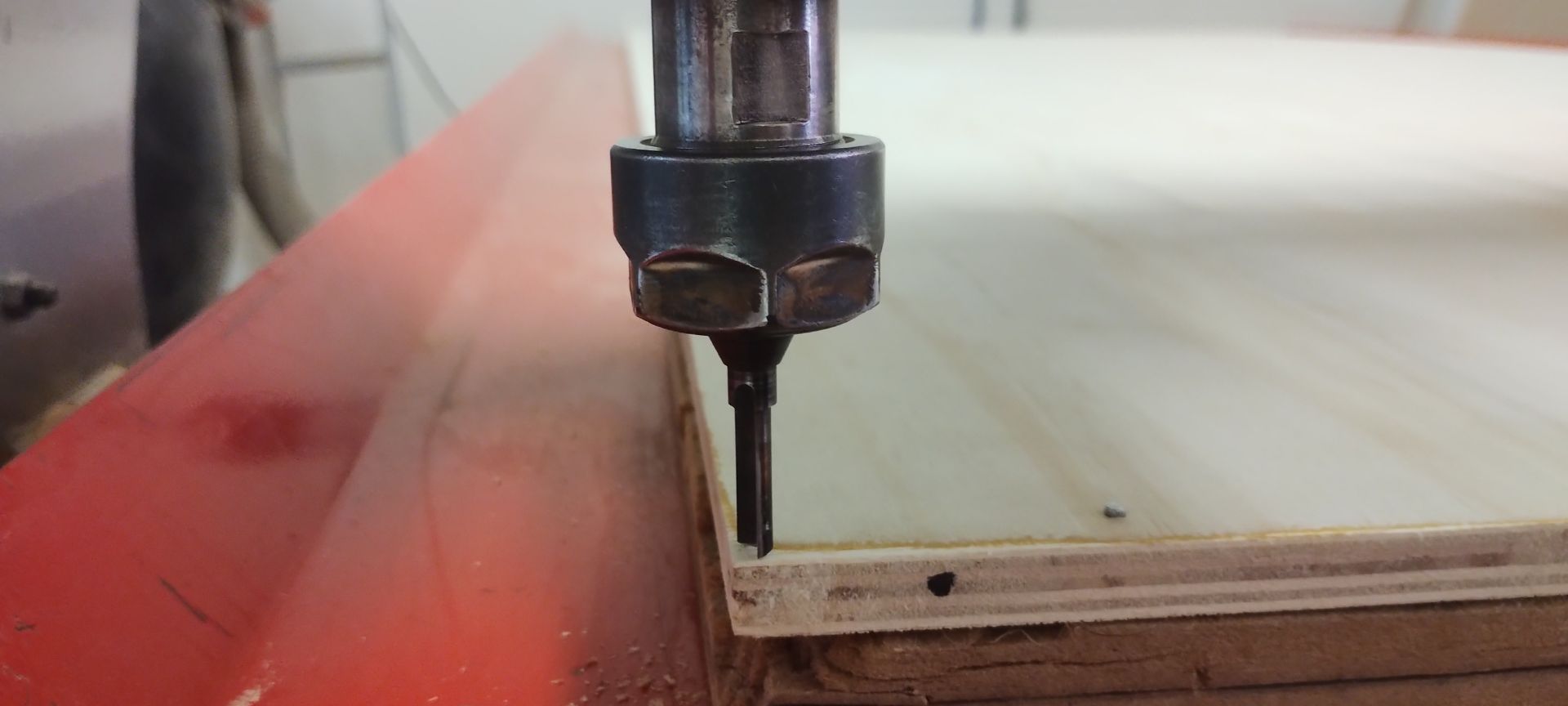
1. Prepare the material on the machine
First, place the material on the cutter and align it with the wooden base already on the machine.
2. Nail the plywood around the edges
Preferably nail all the nails into the parts of the material that appear most warped, to prevent issues and lifting during cutting.
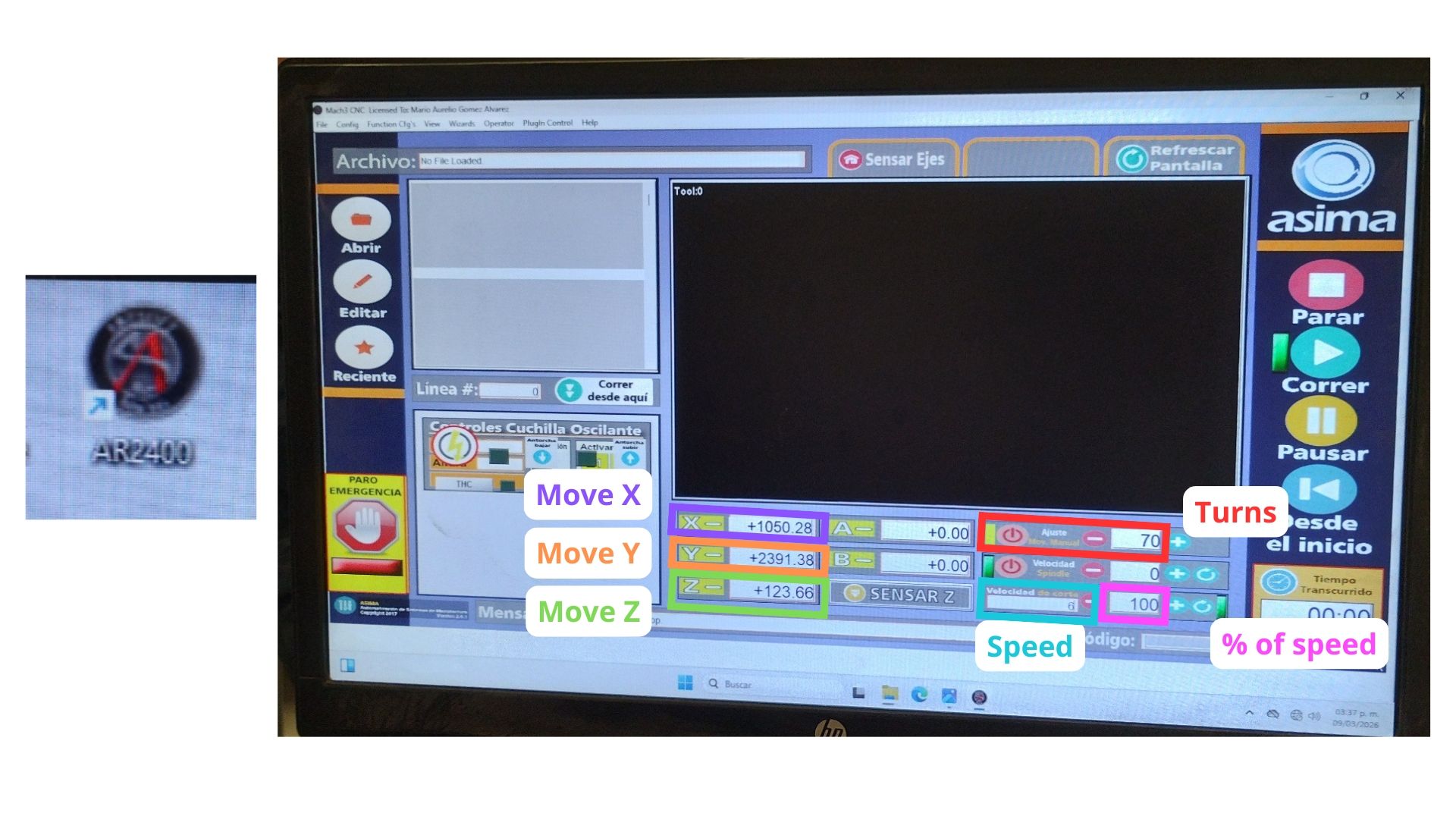
3. Open the software
Open the "AR2400" program on the machine's computer and load the file where my .txt document is saved.
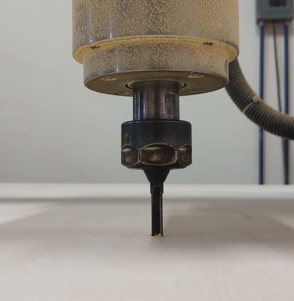
4. Configure the Z axis
Using the left side menu of the software, raise the bit and center it over the material. Then lower the Z axis until it touches the material. Finally, click "-Z".
Note: It is important to manually rotate the collet while lowering the bit to the material, to avoid losing its edge.
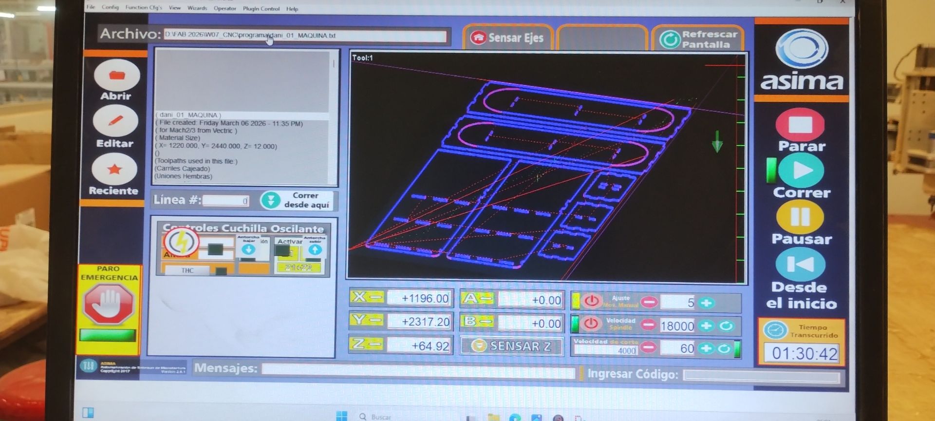
5. Set the software parameters
It is vital to reduce the speed to 50%, otherwise the bit could burn the material by moving too fast.
6. Configure the Y and X axes
Set the origin point (0, 0) at the far left corner — it must match the origin set in the VCarve file. Click "-Y" and "-X" to tell the machine that is the (0, 0). Then raise the Z axis and click "Run" to start the cut.
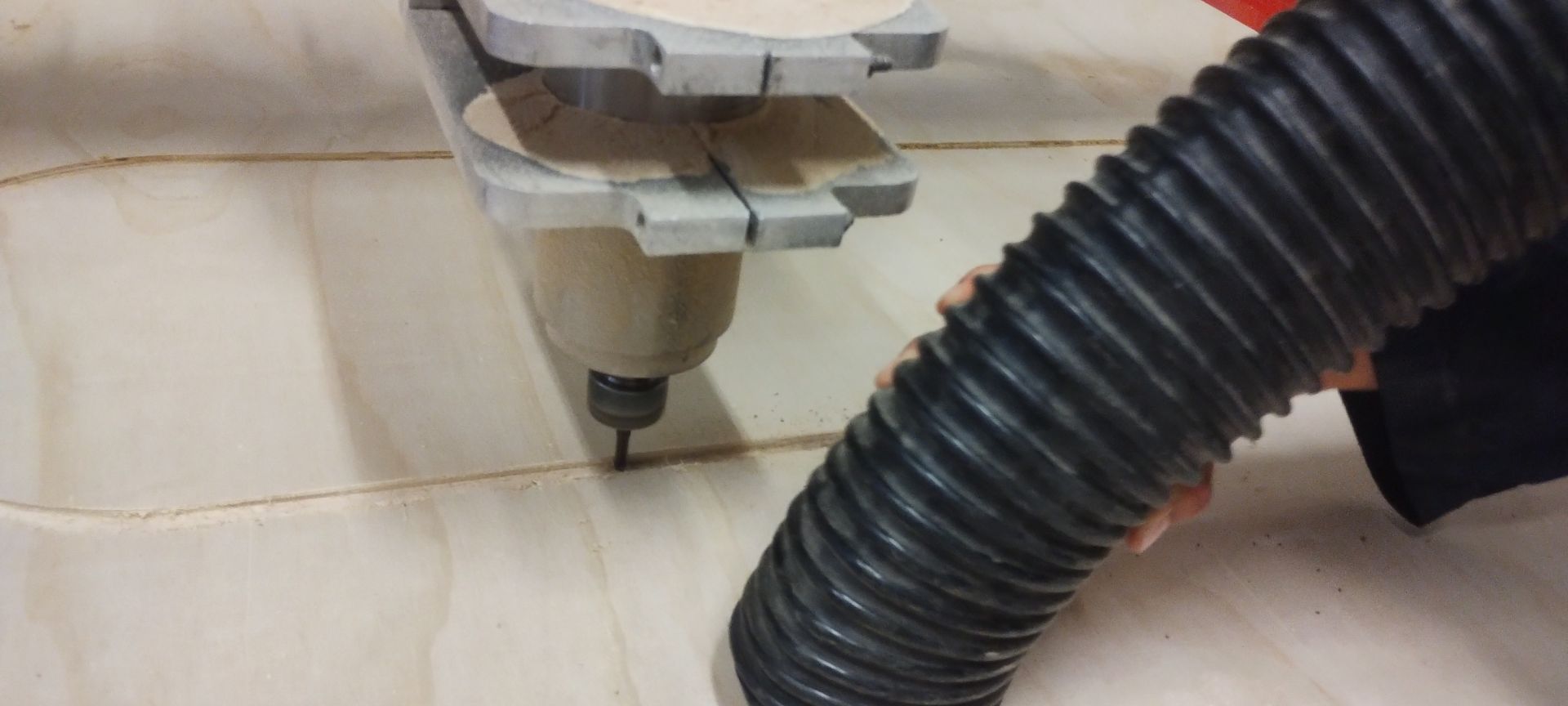
7. Turn on the vacuum
While the bit is running, it is necessary to vacuum the sawdust produced by cutting the material.
Note: This step is vital — without it, friction could cause the material to start burning.
8. While cutting…
While the machine is cutting, it is important to stay alert, as some pieces can shift and fly off once they are fully cut.
Issue I encountered
Since the material was warped, the pocket cut went deeper than expected and even cut all the way through the material. To fix it, I placed a 3 mm MDF sheet underneath and secured it with wood screws.
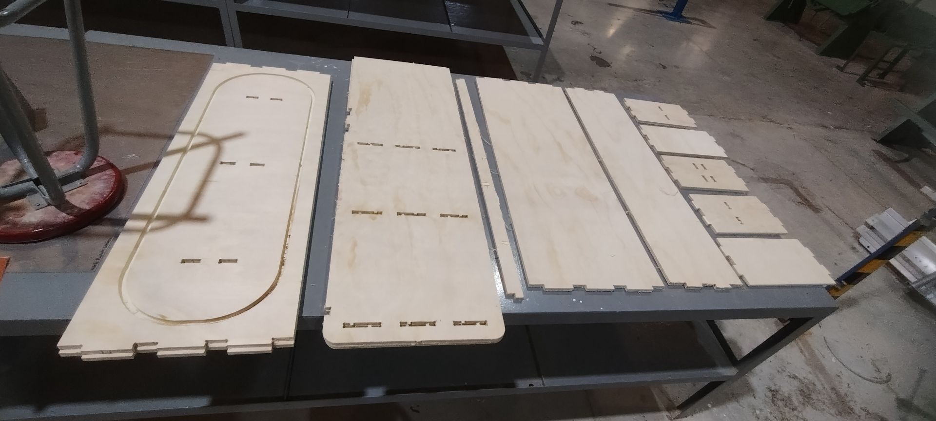
In total, the number of pieces was more than 16.
Extra
Post-processing
To achieve a more professional finish, I painted the whole unit with oil paint so that it would blend in with the woodwork in my home. My dog loved the result as well, and it has now become her little home. 🐶🐾
Materials
- 100-grit wood sandpaper
- 320-grit wet sandpaper
- Bastard file
- Latex gloves
- Face mask
- Preventive wood pesticide
- Sponge
- Oil-based wood stain
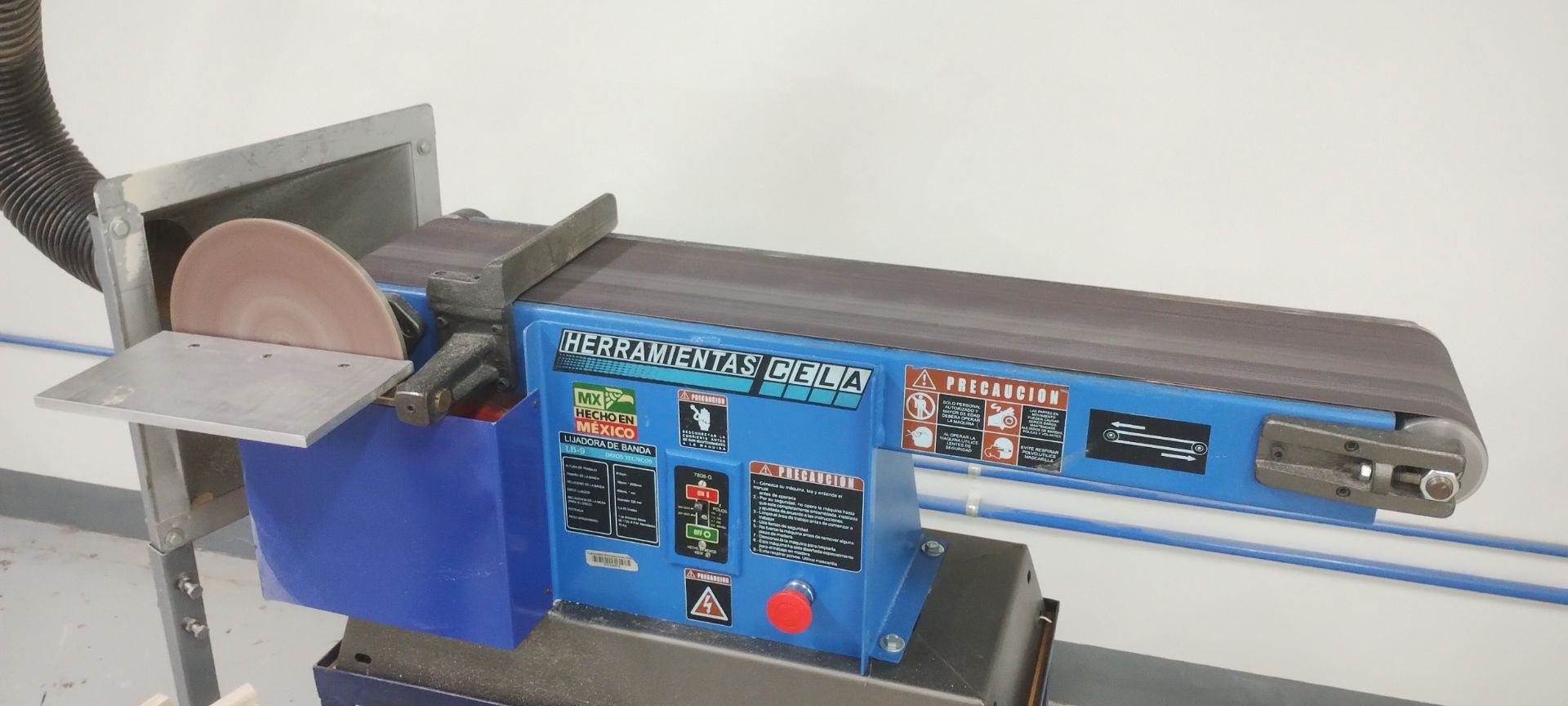
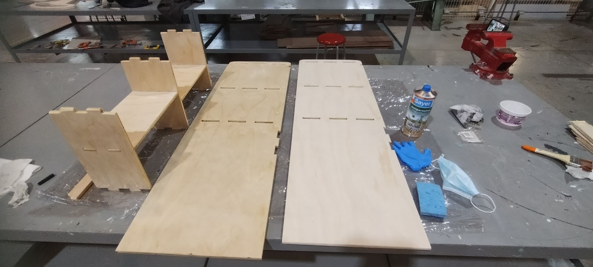
Once the wood was cut, I sanded all the edges of the pieces using a belt sander to speed up the process.
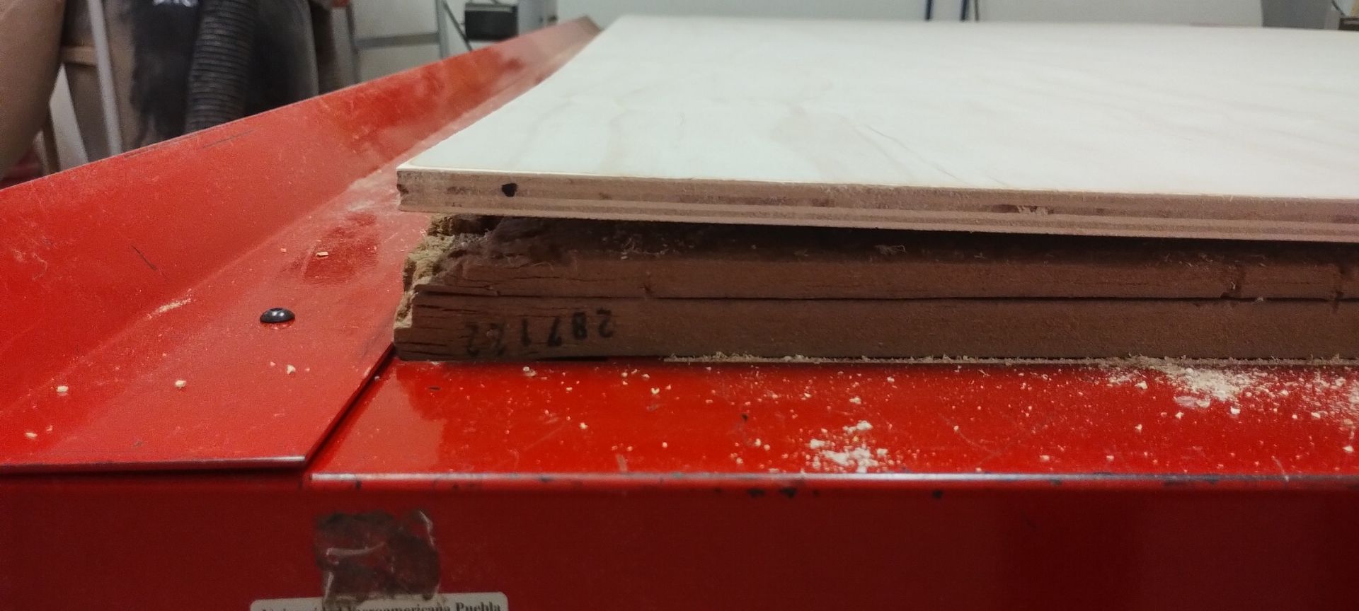
This gives a better finish, especially to the strips that will form part of the living hinge. As seen in the image, the pieces on the left are unsanded; on the right, the sanded ones.
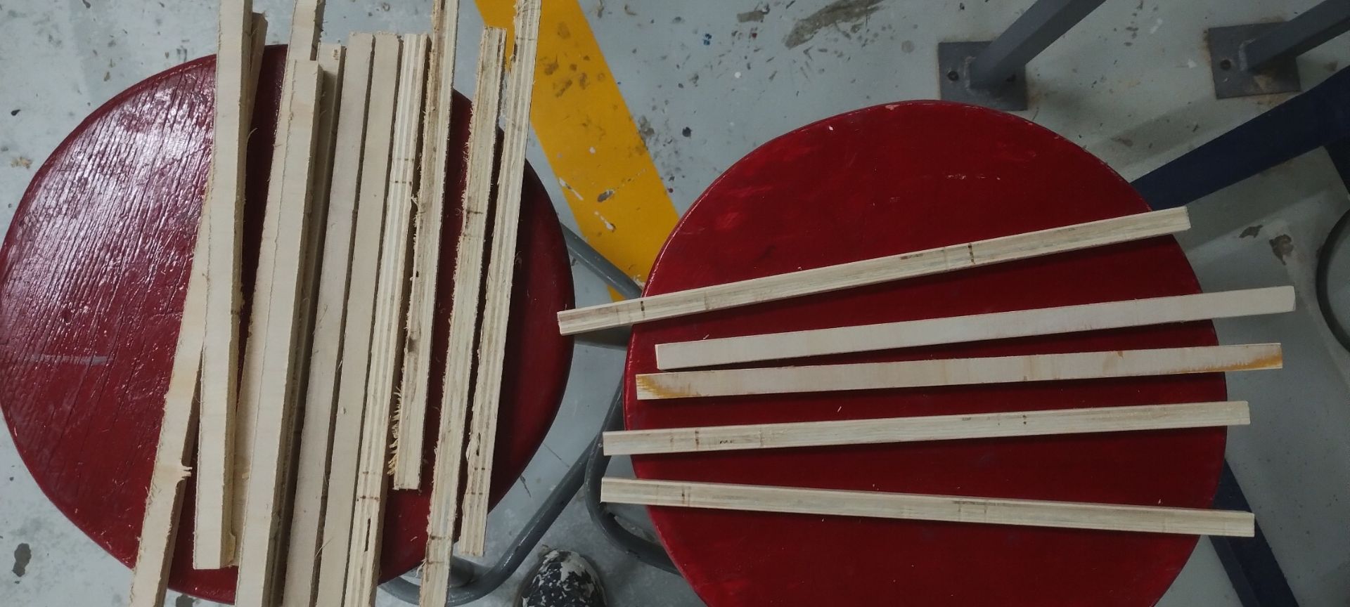
Left: unsanded pieces. Right: sanded pieces.
If there was any remaining burr on the sides, I removed it with the 100-grit sandpaper. Then I applied the final finish with the 320-grit sandpaper, and also sanded the entire surface of each piece for better adhesion of the products.
Afterwards, I applied the preventive wood pesticide using a sponge.
Caution: The smell is strong and harmful, so it is important to wear a face mask and latex gloves.
Once the pieces were dry, I repeated the same process to apply the wood stain. Unfortunately, due to the issues that came up during the week, I was not able to finish painting it — but I will do so later.
The assembly process is shown in the video below.
The final result of the furniture looked like this.
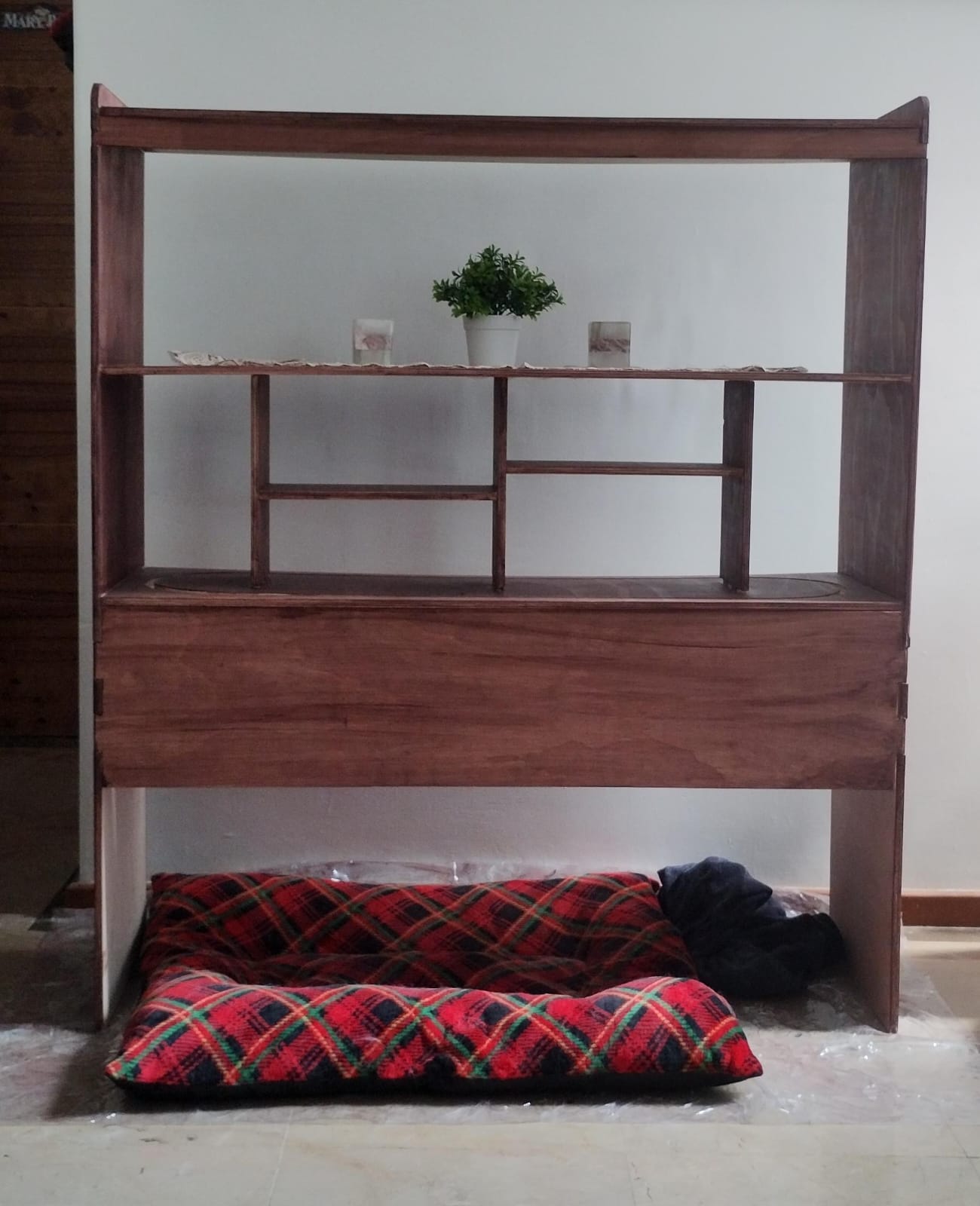
This looks like the final result on the top of my bed. Furthermore, I added a soft light as an indirect source of lighting.

What I learned this week:
- I learned the full workflow in VCarve Pro: importing DXF, defining material dimensions, joining vectors, applying fillets to female joints, configuring profile cuts (Outside/Inside/On) with tabs, and simulating before exporting G-Code.
- I understood that when the material is warped, pocket cuts can go all the way through; the solution was placing a 3mm MDF sacrificial sheet underneath and securing it with screws to level the surface.
- I learned the finishing process: sanding with a belt sander followed by 320-grit sandpaper, applying preventive wood pesticide, and finally using oil-based stain for a professional finish.
What I learned from the group page:
- I learned that cylindrical CNC tools always leave a radius in internal corners, making it necessary to apply "Dog-bone" or "T-bone" techniques in the design so that male parts fit correctly into slots.
- I understood the Shopbot parameter table (Feeds & Speeds) for different bits and materials, and how "Chip Load" determines the efficient material removal rate without overheating the tool.
- I learned about the two material clamping systems: T-slots with adjustable clamps for heavy milling, and a threaded hole plate for custom setups that protect the machine bed during through-cuts.
Files I used this week
solidworks_files.zip
Solid Works Files
Files:
- 01_Side panels
- 02_Bottom header
- 03_Shelves
- 04_Inner drawer sides
- 05_Left inner drawer side
- 06_Right inner drawer side
- 07_Drawer bottom support
- 08_Perforated drawer support
- 09_Stop
- 10_Top stop
- 11_Bars
- Assembly