Machine Design
This week we took a look at Machine Designing. For this assignment, teams where made in order to create a CNC machine from scratch, using everything we have learned from this Fab Academy and our individual careers.
As the resident software engineer of the team, I was in charge of the software side of the machine. For me it will be quite the challenge, as I have no experience with CNC programming, and our machine demands some precise movement that will be hard to achieve with the basic stepper motor functions we know.
Check out my Group’s Assignment Page for the general explanation of our machine creation. Please also check my partners’ week assignment pages to better grasp the whole process and effort we put into our final machine.
Our Machine Requirements
Before even writing a single line of code, we need to determine what our machine needs to do. Our machine does one single task: inserting samples into a petri dish. However, this simple task requires the combination of different steps to achieve the goal.
The machine we are basing our project from is quite complex on its functionality. So for our timestamp, available resources and experience, we had to cut the desired functionalities to the bare minimum operational capabilities. With this in mind, our machine’s work flow will be looking a little bit like this. This diagram must be repeated for every dot on the drawing:
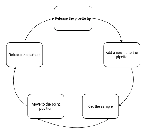
This will be the workflow for our machine. Luckily for us, this workflow comes with some advantages. For starters, no user input will be required to configure the origins of the machine. The machine will always use the same coordinates as every element of the machine (more on that later) will stay in the same position every time. Secondly, our movements are quite simple: x, y and z axis movement plus a mechanism to release the pipette content and release its tip.
In reality, we are building a simple 3-axis CNC with extra functionalities for handling the pipette. This means, that we can use something as grbl to control our CNC, which makes my life quite easier.
For now, a bigger problem arises: we need a way to design our petri dish pattern and convert it into the GCode that our machine with grbl will follow.
The Petri Dish Design
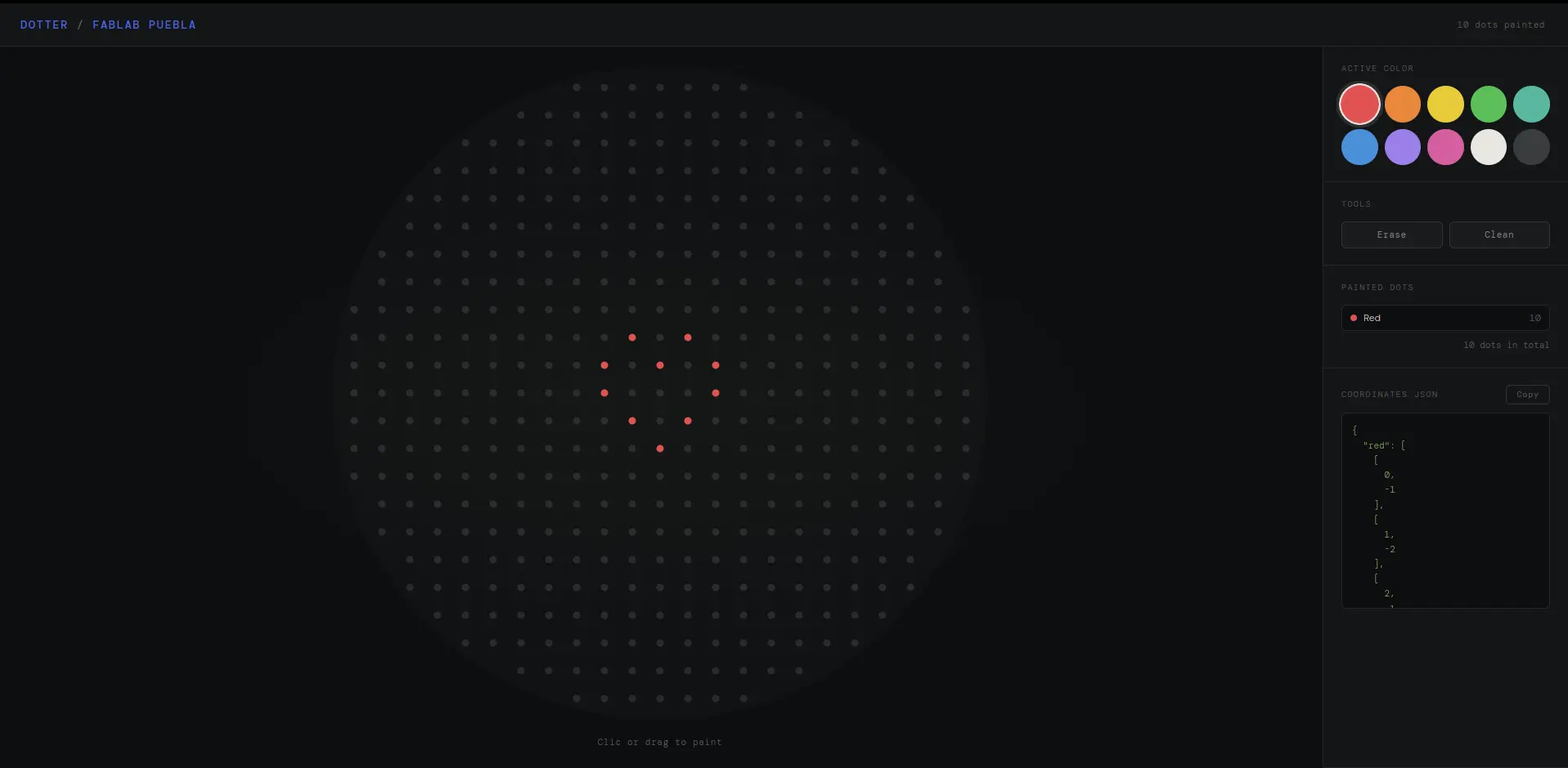
We need a way to design the patter on the petri dish. Our machine is based on Opentrons bio-mechanical machines. Opentrons used to offer a web page that allowed the user to draw with colored dots the design they desire. This page would return a series of coordinates of each point, that would then be passed trough their machine. Sadly, the web page no longer allows exporting the dots coordinates.
As a little side quest, I tried “vibe coding” a replica of this page using Claude AI. Little did I know Claude would return me the exact project I was looking to build. With some modifications from my end, I ended up building Dotter, a free to use web page to design petri dish patterns and exporting the dots coordinates. Dotter is completely opensource and free to use, you can find its source code on my personal GitHub page. Any additions to my project are welcomed!
Converting Coordinates to GCode
We have our coordinates ready to go thanks to Dotter. Now we need a way to convert them into GCode for our gbrl to read. There is no direct way of converting coordinates into GCode, so this will require a custom script.
Understanding GCode
One of our local instructors once told (during the CNC week) that we where really lucky to have software that automatically created our GCode, as when he was a student he had to write it by hand. I never really understood how you could write GCode “by hand” until I took a look at how GCode works.
Essentially, GCode is a programming language that tells the machine how to move. GCode works with “Codes”, or specific commands meant to achieve the movement we desire. For example, in order to move to an specific location, GCode writes G0 X100.000 Y0.000 F3000. This might be intimidating at first, but once you take a deep look on how the instruction is written, it becomes easy to understand.
The code has 4 parts:
G0is the movement command. It tells the machine that the following text are movement instructions.X100.00is the X movement. It will be moving 100 units (the units are defined with GCode as well).Y0.00is the Y movement. It behaves exactly like the previous command.F3000is the speed of the instruction, or how fast will the machine move.
There are many GCode codes available. For more information on GCode, check out this cheatsheet page.
Building the Script
Now that we understand how GCode works, translating our coordinates to GCode is quite straight forward. A python script would look something like this:
for color in JSON:
        	for coordinate in color:
        		write(f"G0 X{coordinate.x} Y{coordinate.y} F{speed})
Following this logic, our scrip can translate any number of dot coordinates into the movement the machine will have to make in order to position itself. However, moving the machine is not enough, as we also need to handle te following functionality:
- Pipette press and release
- Machine movement in the Z axis to lower the pipette
- Pipette tip release (in the trash bin) and fixing of a new tip
- Sample taking and placement
Plus, the script will constants for each hard coded positions of our machine, like the trash bin placement and petri dish origin (coordinate 0, 0).
So I started coding, no AI was involved on the development of this script.
After some trial and error, I got a GCode file to test. I installer Universal GCode Sender to visualize the GCode file I generated from my script. This was the result:
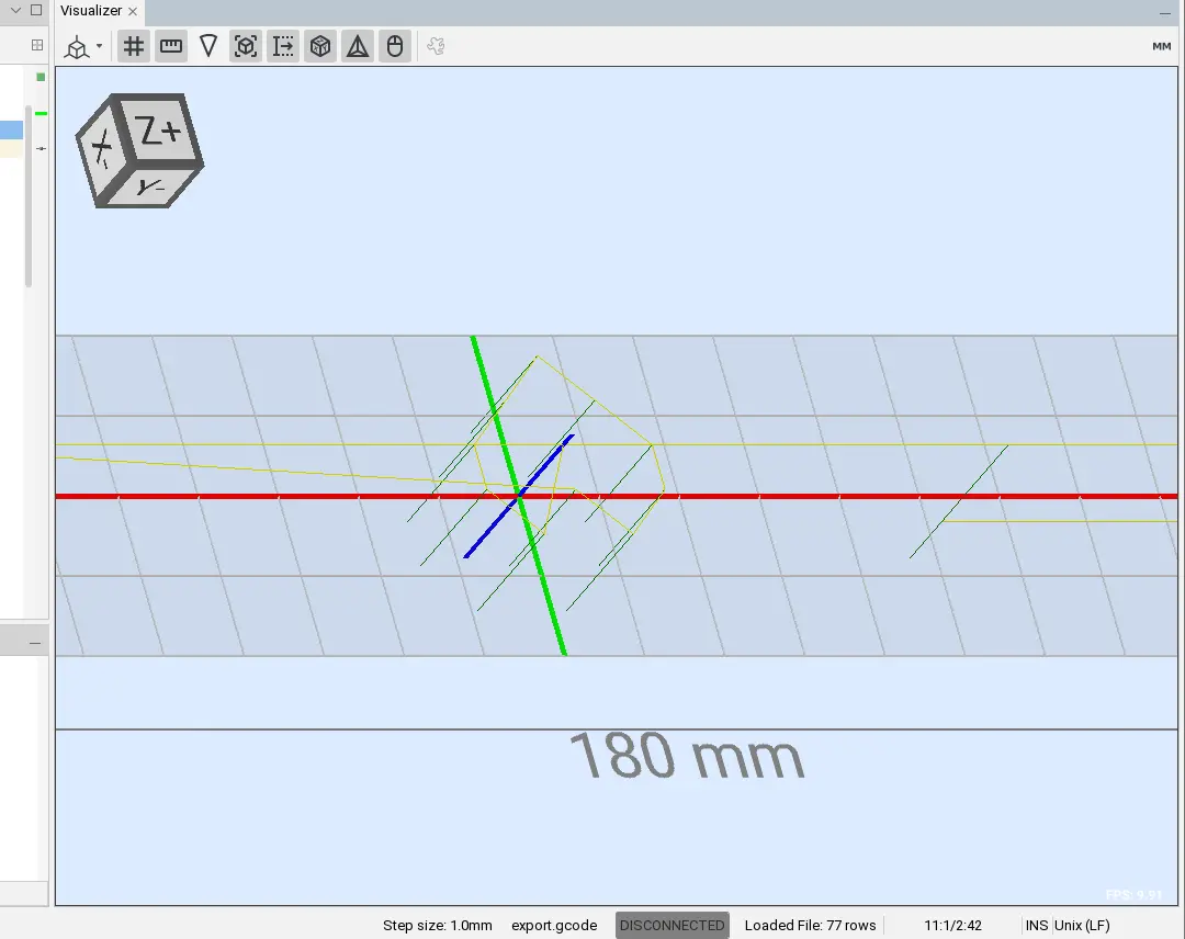
It might be hard to appreciate, but there it is! A heart shape made out of dots, with its tool path and insertions defined. This was genuinely a surprise for me, as making this script was easier than I anticipated in the end.
The only thing remaining is hard coding the base positions of our machine, but for this we need to make some testing with an already working prototype of the final machine.
My python script is also available to the public. I decided to transform my script into an easy to use web page using flask and python. You can check it out at Dotter GPlotter. The source code of this page is also available at mi personal GitHub Page
GRBL
Grbl is an open source CNC control and GCode parser firmware meant to facilitate the process of making and controlling custom CNC’s. Grbl comes pre loaded with the essential functionalities needed to “plug and play” into your CNC. For more complex machines, custom software is ideal, as it allows for more optimization and personalizaron. For our use case, our machine is a standard 3 axis CNC with extra functionalities (pushing the tip release and sample release buttons on our pipette). This is why grbl is ideal for our use case: everything we need to control our CNC will be ready from the get go.
FluidNC
We are most likely to be using an ESP32 as our CNC’s brain. This ESP32 will be connected to the CNC shield we’ll be using. Grbl is not meant to be ran on an ESP32, but there are a couple of forks, or variations of the project that we can use.
FluidNC is a grbl fork made to be run on ESP32 micro-controllers. With FluidNC, preparing our ESP is as easy as loading the firmware into it and configuring some parameters (more on that later). FluidNC has a great wiki page that guides you through the installation, configuration and usage of the firmware. Plus, I recommend NEWTech Creative’s video walk-trough video on how to install FluidNC into an ESP32.
Configuring FluidNC
Once FluidNC is flashed into the ESP32, it is not quite ready to go then. Every CNC is different, and requires certain custom parameters to work at its best capacity. To configure our ESP32 for our CNC, we need to create a config.yaml file. This config file defines all the important operation parameters for our CNC.
Writing this config file is easy, but requires some understanding of your machine and trial and error tests to get the best parameters.
Here’s and example on how a config.yamlfile looks:
name: "ESP32 Dev Controller V4"
        board: "ESP32 Dev Controller V4"

        stepping:
          engine: RMT
          idle_ms: 250
          dir_delay_us: 1
          pulse_us: 2
          disable_delay_us: 0

        axes:
          shared_stepper_disable_pin: gpio.13:low

          x:
            steps_per_mm: 800
            max_rate_mm_per_min: 2000
            acceleration_mm_per_sec2: 25
            max_travel_mm: 1000
            homing:
              cycle: 2
              mpos_mm: 10
              positive_direction: false

            motor0:
              limit_neg_pin: gpio.17:low:pu
              stepstick:
                direction_pin: gpio.14
                step_pin: gpio.12
            motor1:
              null_motor:

          y:
            # Same config as X axis

          z:
            # Similar config as X axis, with some variations
As you can se, it is pretty intuitive. You can check FluidNC’s wiki for a more detailed list of every configuration available.
Configuration for our machine will be a combination of this config file and the hard coded parameters in our GCode script.
Installing FluidNC
Installing FluidNC into our ESP32 is quite straight forward. You can use FluidNC’s web installer, which is the current most recommended method by the developers. First of all, we need to install the ESP32 driver for our machine. Go to Silicon Lab’s official web pageand download the driver for your system, in my case the CP210x Windows Driver. Unzip the downloaded file and run the .exe file that corresponds to your system’s architecture, either x64 or x86. Follow the installation wizard, and when the installation is done we can connect our ESP32 to our device.
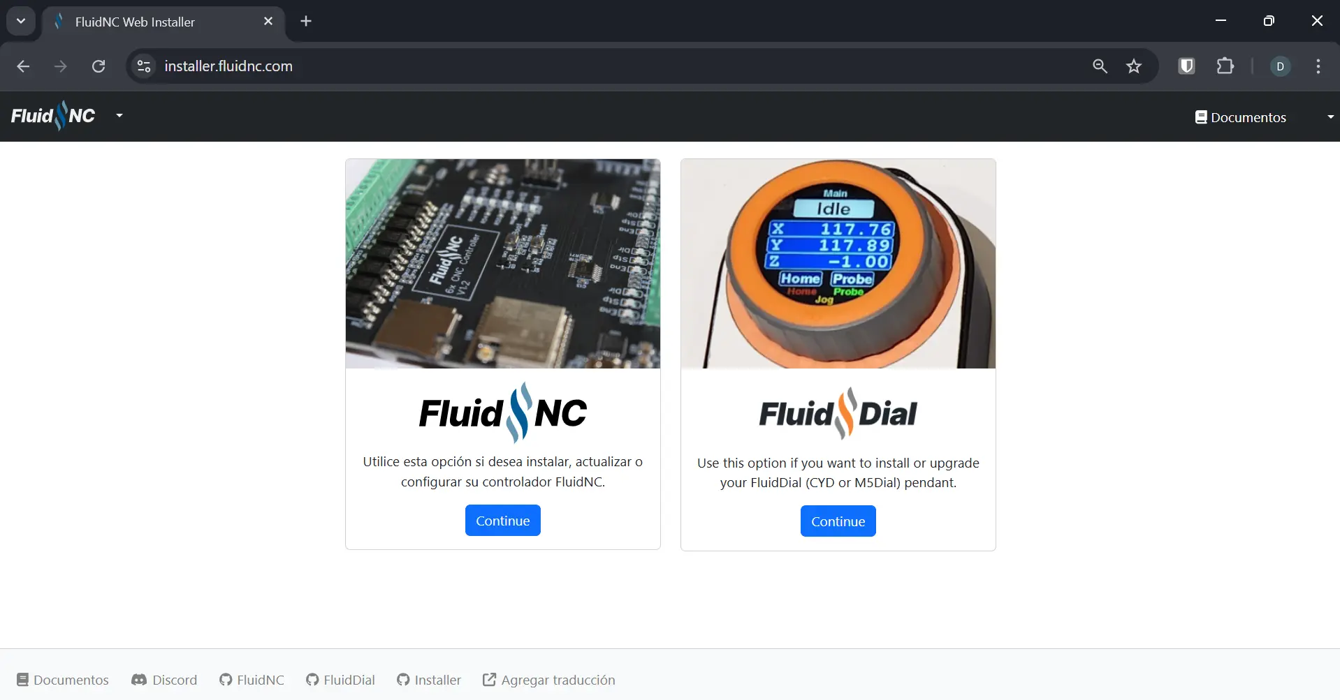
Now, go to the FluidNC’s web installer, and select FluidNC:
Note: Some browsers, like Firefox, are not compatible with the FluidNC web installer. We’ll be using Google Chrome, as it is the most widely used compatible browser.
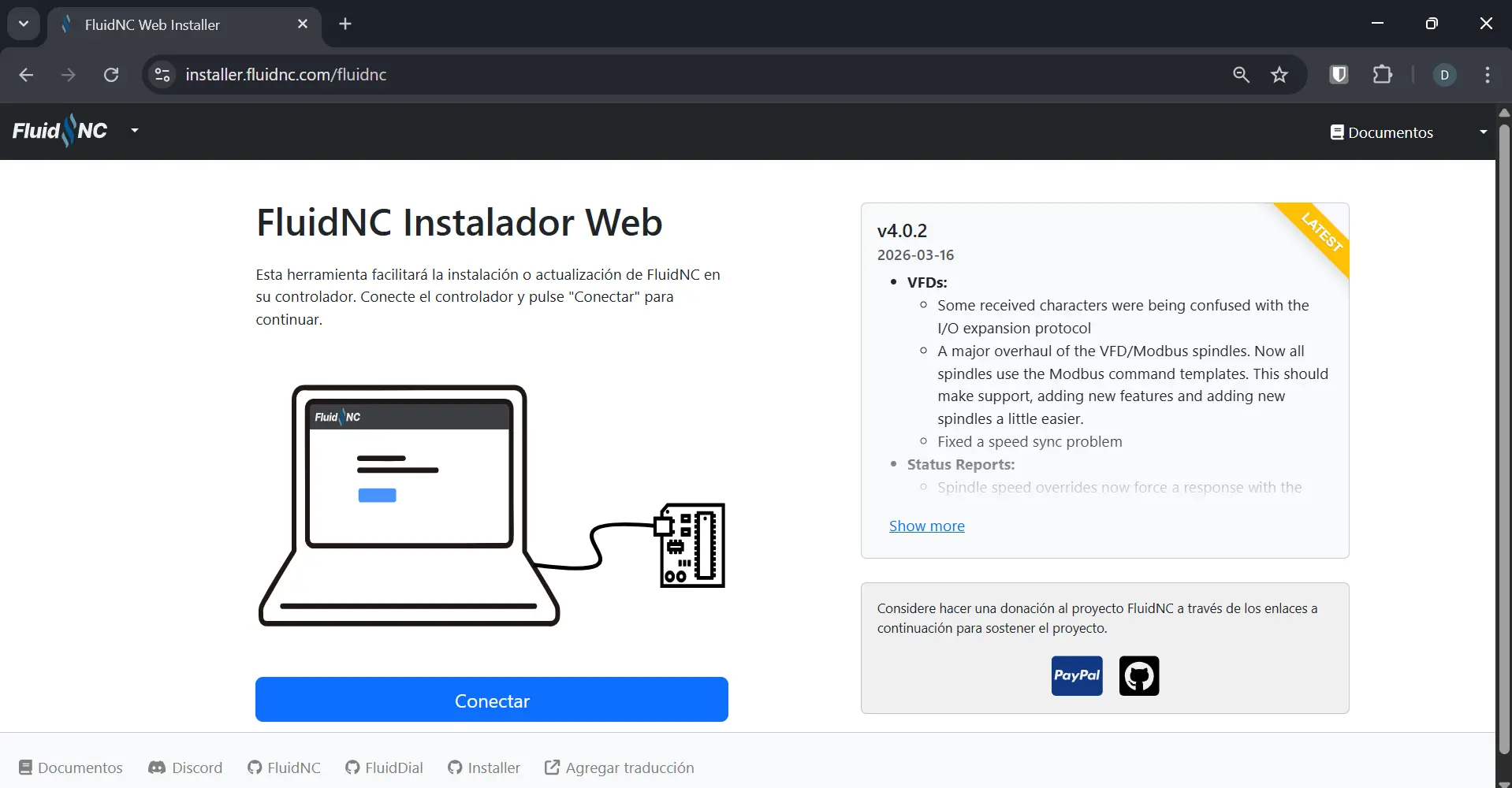
Connect your ESP32 to your device and hit the connect button:
A window may appear on your browser, asking you to select your port. Select your board (most likely the only option available) and click continue.
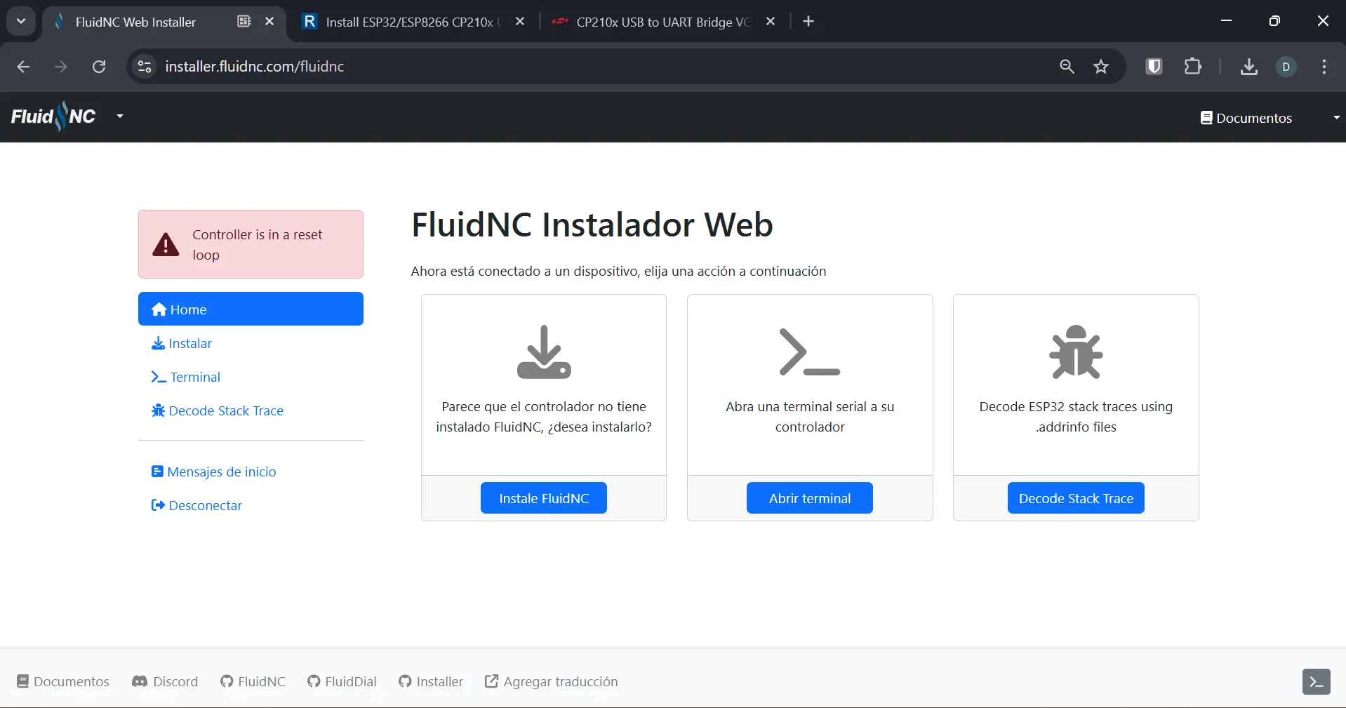
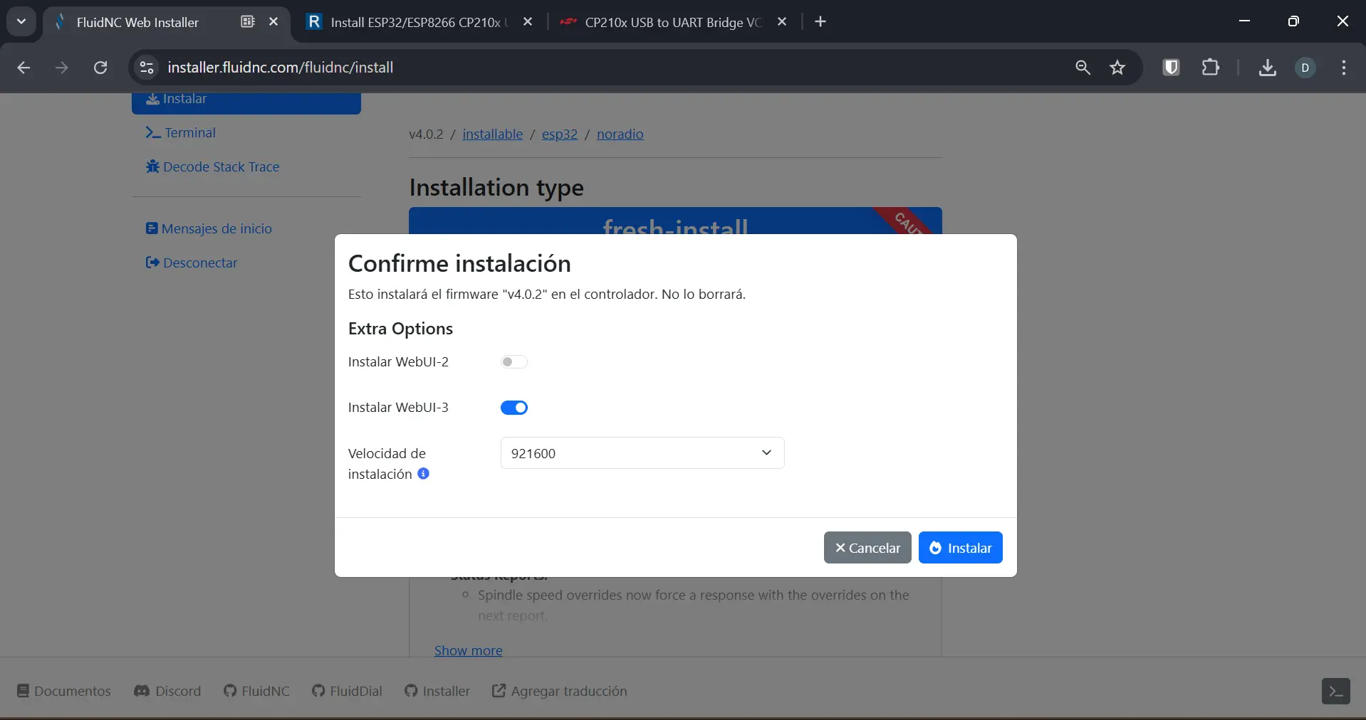
You must select the Wi-Fi option, as this allow us to use the WebUI control panel(more on that later). If your board has no Wi-Fi connectivity, or you prefer to go with no Wi-Fi, select the noradio option. Once you’ve selected your install option, click the “Install FluidNC” button. A window will appear. Select either the “Install with WebUI-3” or “WebUI-2” options. This will be our CNC’s control panel. Once you have selected an option, click “install”.
Once the installation is over, a new window will appear. This will be our FluidNC main control dashboard.
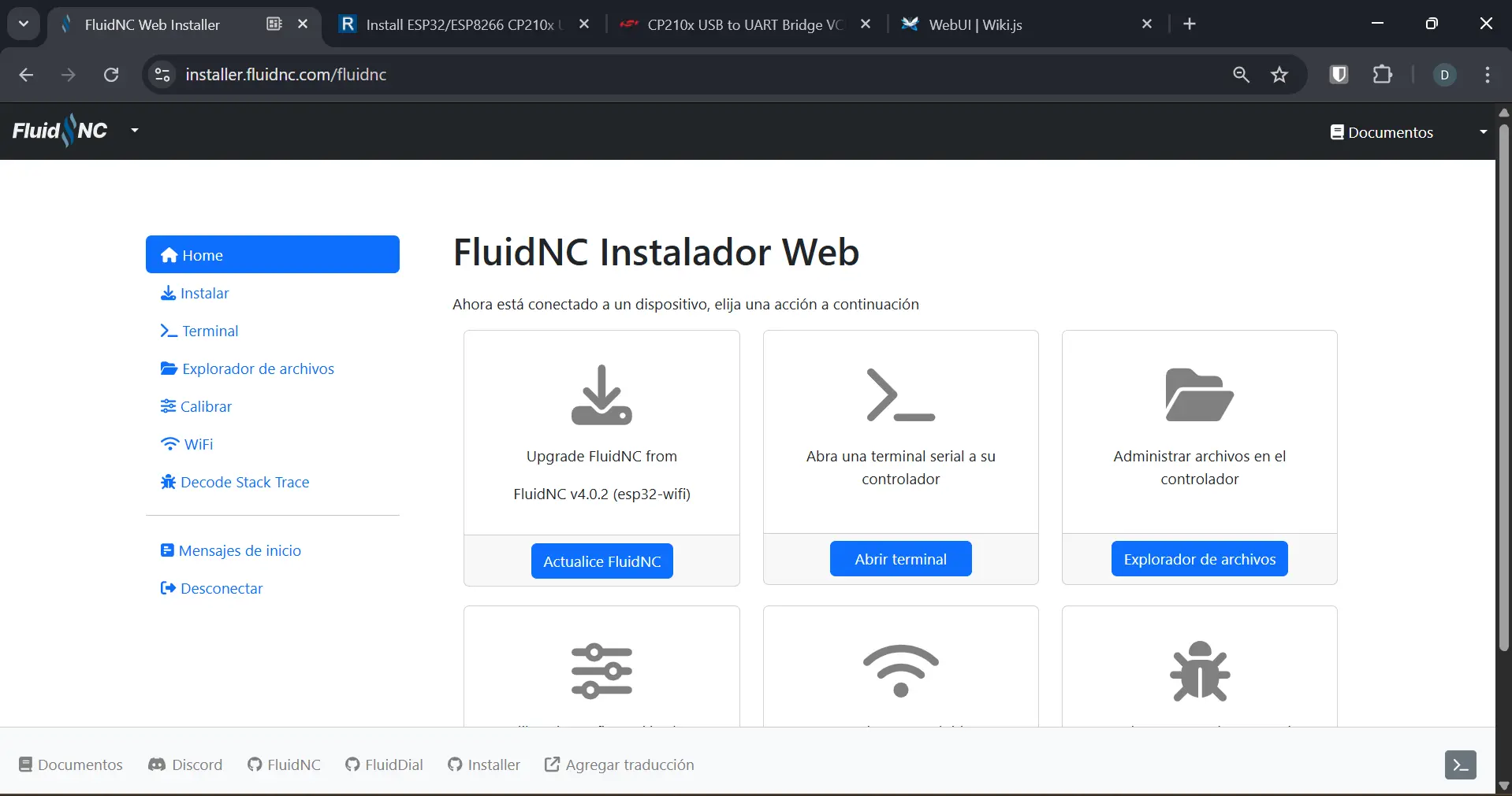
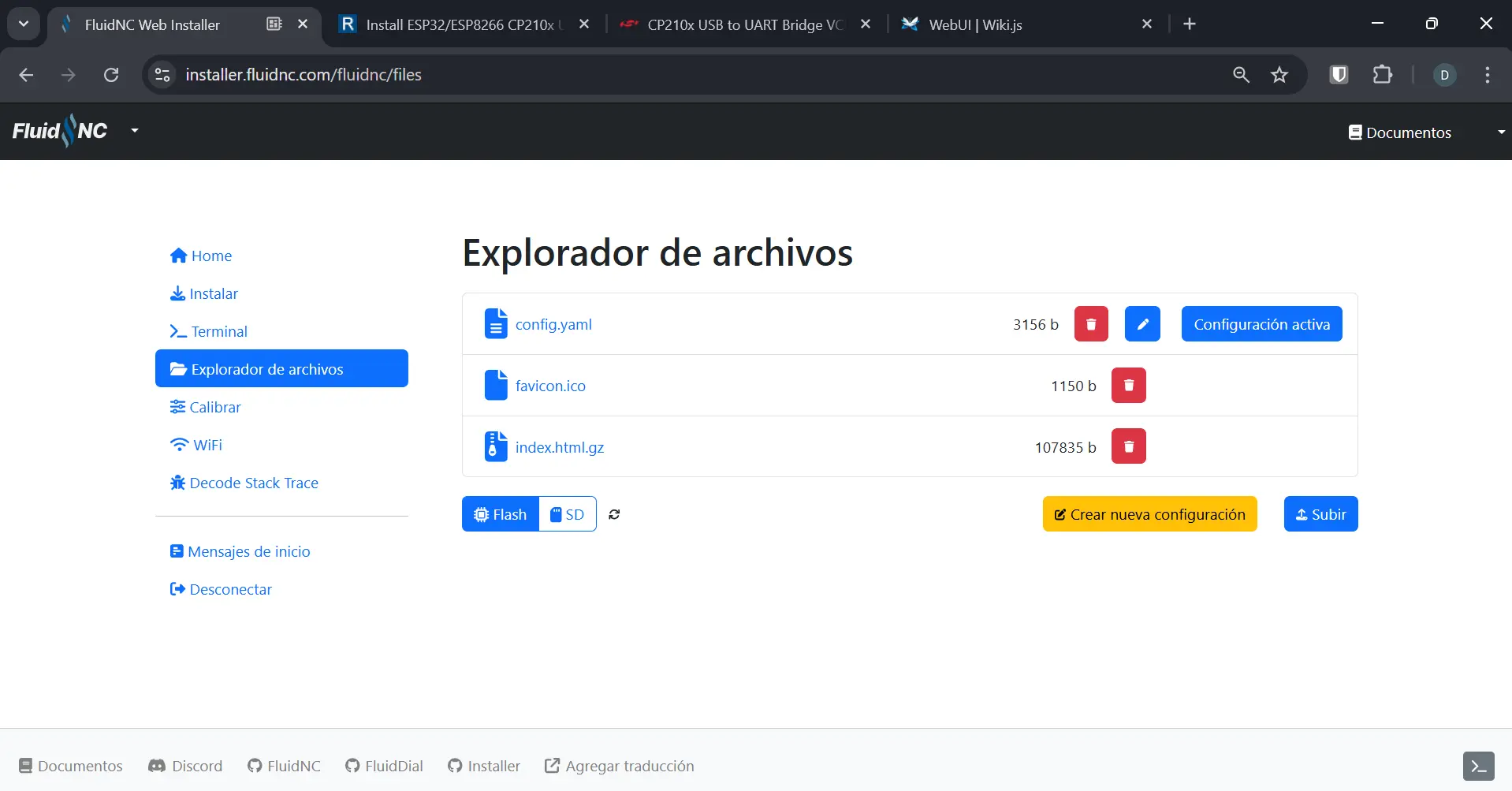
Travel to the “File Explorer” tab on your side bar. Now, click the “upload” button and upload your config.yaml file. This page will also allow us to fine tune our config parameters without having to re-upload our entire config file. This will come in handy when testing our machine.
Now, travel to the “Terminal” tab. The terminal will allow us to see the state of our machine. For staters, witre ? on your terminal. A text similar to this one will appear:
<Idle|MPos:0.000,0.000,0.000|FS:0,0|WCO:0.000,0.000,0.000>
If instead of “Idel” you get something like “Alert” on red text, it means something is wrong, most likely the config file. You can verify your configuration for errors on the FluidNC installer page. If something is wrong with your configuration, a message will appear.
Connecting to the WebUI
FluidNC comes installed (if chosen to) with a WebUI on its Wi-Fi version. This WebUI allows us to control the basic aspects of our machine, in this case movement as we do not use spindles or lasers. To connect to the WebUI you installed (in our case WebUI 3), connect to your esp32 through Wi-Fi. A Wi-Fi network called “Fluidnc” should appear on your device network manager. Connect to it using the password “12345678” and go to fluid.local on your browser. You are now on the WebUI of FluidNC.
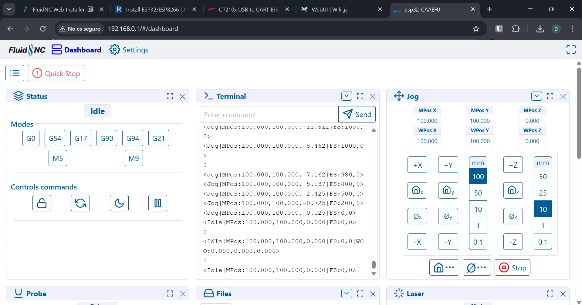
We are only interested on the “Jog” and “Terminal” tabs of the WebUI for now. Everything else you can close. If you ever need any of the closed tabs, you can re open them on the 3 bars side menu to the left of the “Quick Stop” button. The “Terminal” tab works the same as the terminal on the FluidNC installer. From here you can check the state of the machine, plus run GCode directly from it. The “Jog” tab will allow us to move our Axes independently 0.1, 1, 10, 50 or 100mm at a time. Once our machine is properly connected and configured, it would only take a single click to the desired axes + direction to move it.
The Change of Plans - Light Drawing Machine
As explained on our Group Page, there was a big change of plans regarding our machine’s purpose. In short, our machine had a big design flaw, that would prevent it to work properly. The pipette placement and weight caused it to behave like a lever, which caused the pipette’s tip to move considerably with any X and Y movement, and specially with Z movement. This means that we would have never been able to place the sample on its precise placement.
Our team decided that we where going to re-purpose our machine, as redesigning our current one would take to much time, and we only had a 3 days remaining. We decided to change our machine into a Light Drawing Machine. Light Drawing, also light painting, consists on using any type of light moved in a pattern that, when captured with the right camera settings, results in a drawing.

Rethinking our Machine
Our machine has already its X and Y axes, so we can use them perfectly. We now had to think on how to emit light. We decided to use a neopixel ring as they are widely available on our University. We decide to re-purpose our dotterpage to be the platform we use to create our drawings, which also allowed us to use its colors to change the neopixel ring colors. But with this functionality came a big problem: we needed to think of a way of declaring the LED color change in the GCode, so that FluidNC could understand it and replicate it.
The Neopixel Problem
FluidNC is a great platform for creating any kind of homemade (and even professional) CNCs. It includes options to use spindles, lasers, coolants, etc. This was the main reason why we decided to use FluidNC in the first place: our original machine was just a standard 3-Axes CNC. But now, we need a functionality that is not normal of CNC machines: we need to declare the exact RGB values the neopixel needs to turn on with in the GCode, in a way that FluidNC could understand it.
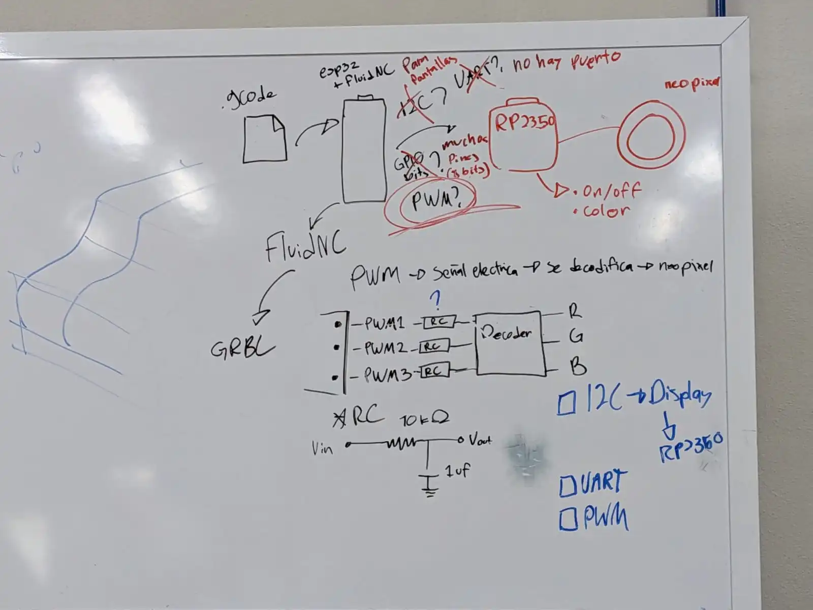
After some brainstorming, I came up with some posible solutions:
- Using the I2C protocol to connect the esp32 with FluidNC to support micro controller that will control the neopixel ring.
- Using the UART protocol to attempt the same goal.
- Using **GPIO **pins to send bit wise data that will be translated by a supporting micro controller (immediately discarded for the amount of pins needed and the amount of pins remaining).
- Modifying FluidNC’s source code to create a custom “M code” that will send the RGB values directly to the neopixel ring.
- Using PWM to send an electrical signal that could be decoded in a supporting micro controller.
Why NOT Modifying FluidNC
The first method that was discarded was modifying the FluidNC’s source code. FluidNC is an open source project, and you can download its source code directly from it’s GitHub repo. FluidNC supports the creation of custom “M code”, or dedicated GCode for certain tasks. The idea was to create a custom “M code” that would look like this: M150 R255 G0 B0. This way, when reading the GCode and finding this M150 instruction, FluidNC would now that it had to send the following RGB values to the neopixel.
For profesional use cases, this would be the go-to solution, as it adjusts the software to our specific use case. I’m a good programmer. But modifying and existing code base, with multiple 2000+ lines of code files, all interconnected to one another, in a few days? It was impossible to achieve. With enough time and understanding of the code base, I’m sure I would be able to achieve it. But for the time being, another solution would have to do.
Why NOT I2C
FluidNC supports the I2C protocol just fine. You can configure pins on your esp32 to be used for SCL and SDA directly from you config.yaml file, like this:
        i2c0:
           sda_pin: gpio.14
           scl_pin: gpio.13
The only issue with I2C in FluidNC is that it is mostly thought for displays. If we wanted to use I2C to send a specific signal, like a string that reads “R255 G0 B0”, to a supporting micro-controller, it wouldn’t be possible with vanilla FluidNC. Again, modifying the source code was necessary. Maybe there was a way of actually telling FluidNC what to send trough I2C, but I couldn’t find it.
Why NOT UART
Initially we were going to discard UART, as we did not plan our logic PCB (the one casing our esp32) to have UART outputs. But luckily (not really), we needed to redo our logic PCB, and we added the UART ports in that iteration.
UART was meant to work like I2C, sending data from FluidNC to a supporting micro-controller. But unlike I2C, there is already a pre-built way of FluidNC to UART for this purpose. FluidNC allows to send messages with GCode like this: (MSG, <text>). This message would be added in our GCode generation script whenever we need to change the neopixel color, some what like this: (MSG, R255 G0 B0). Our supporting micro-controller would have a script that would receive the string through UART, extract the RGB values and send them into the neopixel.
We connected the supporting micro-controller (a Xiao RP2350) to the esp32 with FluidNC, and sent the message. Unfortunately, we received a string of unrecognized characters. We thought that the Xiao was receiving noise from FluidNC’s terminal, as it is configured to check its status constantly. We decided to test the UART with another esp32 without FluidNC to test this theory. For some reason, we had the exact same problem with this new setup. The Xiao was receiving unrecognized characters. We made sure we where in the exact same baud range, but the problem persisted. We have no idea of why this happened.
The Solution: PWM
PWM turned out to be the simplest most effective solution to our problem. Essentially, PWM allows us to send a signal between 0 and 255. This signal is normally used in FluidNC for controlling spindle speeds or laser strength. In our case, is a way to send a number between 0 and 255 to our supporting Xiao RP2350.
Initially I though of sending 3 different signals, one for every RGB value. This came with an issue, as we would have been sending each value at 3 different moments in the GCode. This would cause issues, like turning the neopixel two different colors before the correct one, or latency when waiting for the 3 values to reach the Xiao. Plus, sending an exact value, say 157, would require a really precise mapping of the PWM values and the GCode instruction itself as FluidNC interprets this 0 - 255 PWM signal as a 0-100% strength value.
Fortunately for me, I know data structures. The solution to our problem was to not send the exact 0 to 255 value for each RGB value. Instead, I just need to send a value between 0 and 10. Then, our Xiao will have a dictionary inside it’s script, that this 0 to 10 values to the exact RGB values of a single color. This means that, when sending a value of 1, the Xiao will read it and turn the neopixel into the red color, sending a 2 will turn it green, 3 will turn it blue, etc. With this, we can send the color we desire with a single command line: M3 S25. The “M3” M code is reserved for lasers, but we are “tricking” FluidNC into sending a value we can use. Plus, configuring it into our FluidNC is quite straight forward:
PWM:
          pwm_hz: 50
          output_pin: gpio.26
          enable_pin: NO_PIN
          speed_map: 0=0% 25=10% 50=20% 75=30% 100=40% 125=50% 150=60% 175=70% 200=80% 225=90% 255=100%
In the “speed map” section, we are declaring the PWM values each 0 to 10 number will have. So, for sending our “red” instruction (a 1 on our dictionary), we just need to send M3 S25. Here’s the complete color mapping we used:
| M Code | Color |
|---|---|
| M3 S1 | Off |
| M3 S25 | Red |
| M3 S50 | Green |
| M3 S75 | Blue |
| M3 S100 | Yellow |
| M3 S125 | Cyan |
| M3 S150 | Pink |
| M3 S175 | Orange |
| M3 S200 | Purple |
| M3 S225 | White |
Another useful feature of this solution, is that our dotter page also works with pre defined colors. And as I explained above, we repurposed this page to become our image generator for our machine.
For a more detailed explanation on the actual implementation of this solution in the physical neopixel ring, check out my partner Gerardo Mora‘s Page, as he was in charge of the actual design and implementation of the neopixel ring into our machine.
Re-purposing our GCode Script
My python script that generated GCode from the JSON given by dotter also needed some modifying. Particularly removing everything needed for pipette control, sample retrieving, tip changing, etc. Funnily enough, our script became simpler that before, only needing to generate G1 instructions for the movement and M3 instructions for the neopixel. We ended up making it so that the color changes after moving to its drawing starting position. This change was made because the light starting before the movement caused some images to have extra lines (see our Group Assignment Page to see our results).
The one extra change I implemented to the script was converting it into a command line tool. This change was made for trying to make it so that our script generated the needed code for n seconds of time, the needed time for the camera to capture everything. For my first implementation I just made it so that the script generated GCode for 30 seconds. This solution was wrong, as I was not generating GCode for “a 30 second operation”. I was generating GCode “for 30 seconds”, giving me massive files of GCode.
In the end, after learning how the camera worked and how our pictures needed to be taken, we figured our that repeating the patter for 1 to 3 times was just enough to get quality pictures.
The Bottom Line
This last two weeks where some of the most intense, fun and stressful and, most importantly, challenging and satisfying of my University trajectory. I got to work with some amazing teammates, learning so much about them. It was a shame that our initial machine was not able to be made. But it wasn’t for a lack of capacity, it was more of a combination of a small time frame for such an ambitious project. This project, however, will be made here at Ibero Puebla. Maybe not as part of this FAB Academy 2026, but as an extended, multidisciplinary project involving more students, more professors, more time and resources and, most importantly, everything we learned from this first approach.
As for our final machine, I’m really proud of it. Surprisingly, I think it enraptures more the “spirit” of the FAB Academy than our initial machine. The sense of wonder we experienced after looking at the camera an seeing our first picture was a big reminder for me of why I’m an engineer and why I enrolled in the FAB Academy in the first place. I sometimes think our world does not allow itself to be amazed. Yes, a CNC machine that controls a pipette and places sample with millimeter precision is an amazing project with a real life application. But there is something particularly beautiful in a machine that makes shapes out of light. This wasn’t the “plan b out of desperation” machine we thought it would be. Our LightBrush machine turned out to be the machine we where meant to build. And I’m really proud of me, my team and our machine.
Files
Note: All the files for this project, incuding STl files, Script, configuration files, etc. Can be found in Our Group Assignment Page