CNC Router
CNC Machining refers to a type of machine-controlling tool that allows to program an manipulate machines with a defined purpose: removing from a base material in order to create new shapes. A CNC machine can convert wood, plastic, steel, glass, etc. into a desired object with ease.
A CNC Router is only one of many types of CNC machines. The Router consists of a mounted base with mobility in 3 (sometimes) 4 axis, and a drill bit that´s used to cut the material. Unlike a Laser Cutter (like seen in week 3), a Router can cut thicker and larger material, allowing the user to maker bigger pieces in the end.
For more information on the operation of CNC Routers, check out our Lab’s Group Assignemt Page. From this assignemt I learned the safety requirements for the correct operation of the CNC Routers we have available on our University. Plus, I learned about the basic components of the CNC Router and its basic controlling.
The Assignment
This week´s assignment required us to create “Something Big”. Furniture was a no brainier, as it is not only big but also really achievable with our available material: 12mm Plywood.
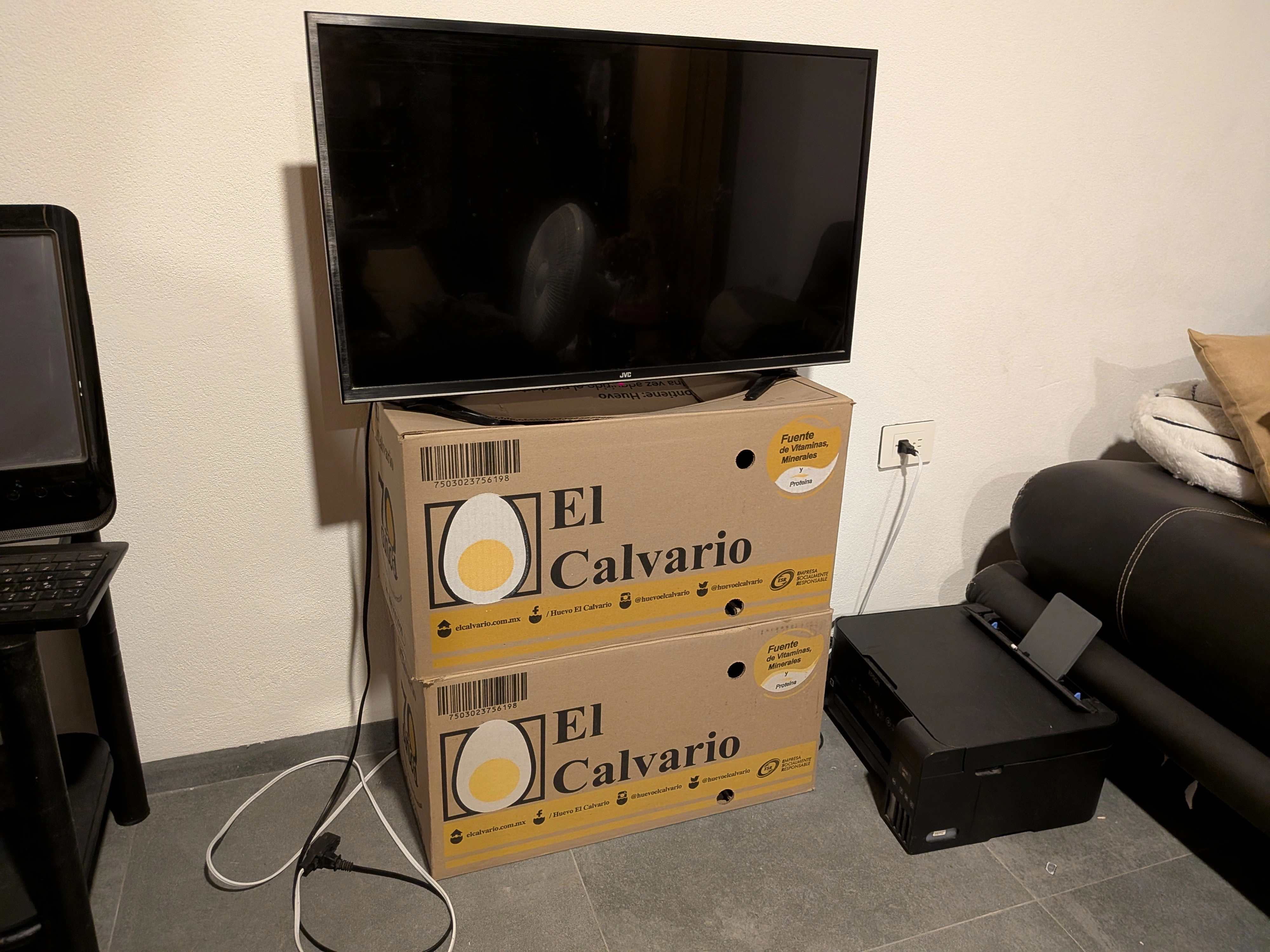
I´m a foreign student, so I rent a decently sized apartment with a friend of mine. I decided that this week´s product will solve a problem we´ve been having since day one: I decided to build a TV stand!
The (Risky) Plan
My plan was to create a TV stand for my living room. This TV stand would have assembling pieces to create it’s structure and would be designed from scratch by me. Plus, I decided to go the extra mile, by incorporating material bending into my design.
I wanted to add a 180° turn into my design. This is often considered an advanced woodcraft technique, but in reality comes down to a couple of key steps that, if done correctly, will result into a beautiful final piece.
The Sketch
Firstly, I designed a quick sketch in a white board on how my TV stand will look:
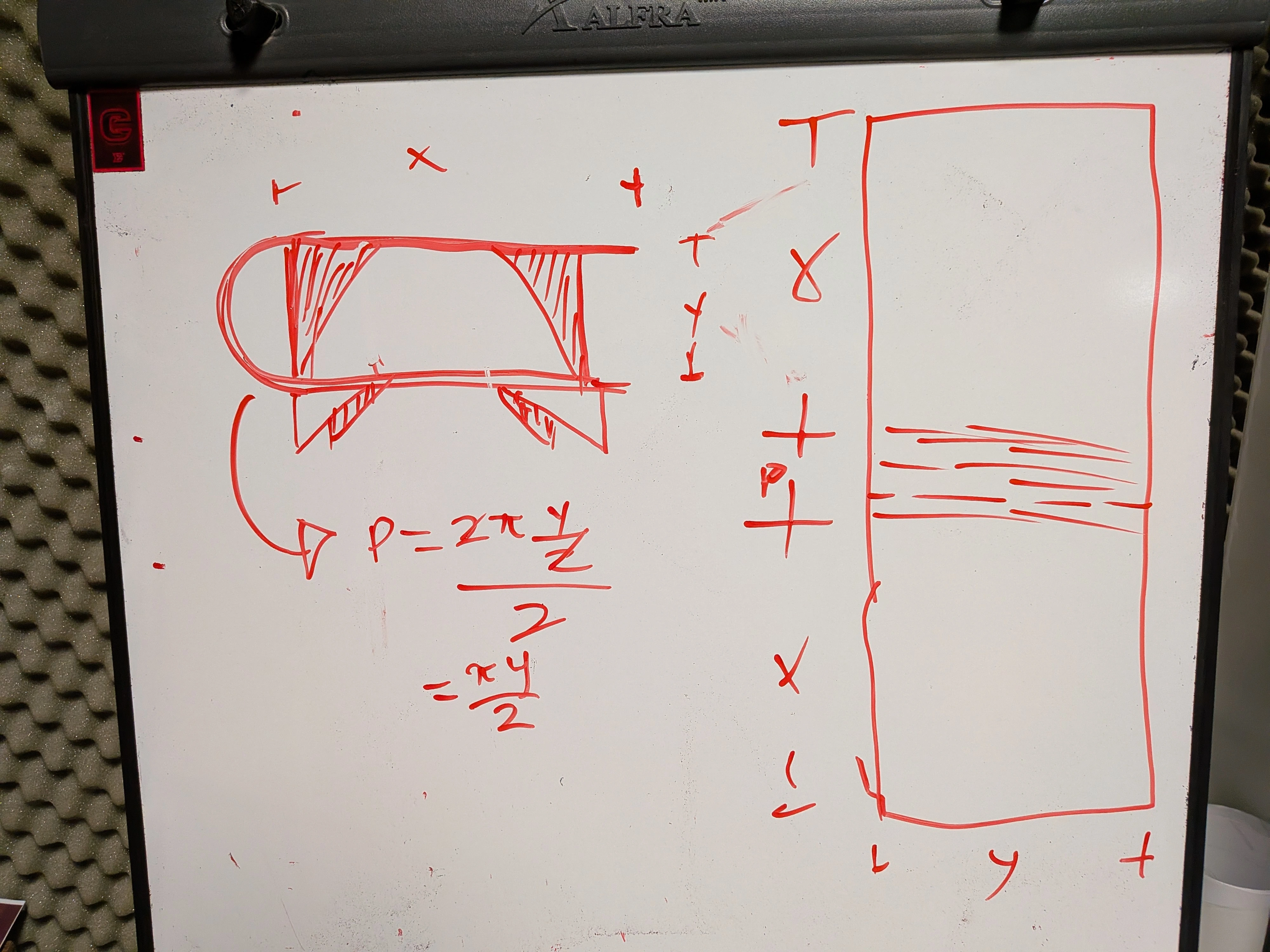
On the top left of the whiteboard there is a quick sketch on how I want my TV Stand to look. As you can see, there is a 180° turn in the material. The design includes some supporting bases for stability, as the TV will be placed on top of it. Plus, some legs to prevent scrapping in the bottom of the stand. On the right side of the white board, there is a preview of the main part of the TV stand body. The piece is divided into 3 sections, two of which correspond to the top and bottom faces. The third face is where our bending technique relies (more on that later). Plus, there are some simple math calculations to better visualize the values I will be working with.
The Kerf Bending
Kerf Bending refers two a technique that involves a series of cuts in the material you desire to bend in order to achieve the necessarily structural imbalance on the material for it to bend. With some calculations, your material will be cut in a way that, with caution and some other tricks, can bend into your desired shape.
First of all, we need to calculate the radius of our bend. This is quite easy, as our 180° bend results in a circle shape. Using the circle perimeter formula and dividing it into two (as we only need one face) we can calculate the perimeter:
Then, we must calculate the number of cuts we need to make into our material in order to achieve the bend. To do this, we must divide the resulting radius between the drill bit diameter:
At last, we must determine the deepness of our cut. This doesn´t require a strict calculation, as leaving between 1-2mm of material is the standard. For our 12mm thick Plywood, cutting 10mm deep for each line will be enough.
Designing The Furniture
For this project I decided to use AutoCAD again. In previews weeks I shared my discomfort using AutoCAD for parametric design. But in this case where fully parametric design is not needed, AutoCAD will help us make our design faster than with my go-to CAD software: OpenSCAD.
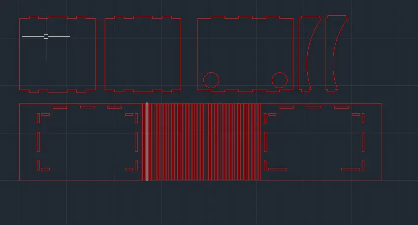
Booting up AutoCAD, my first task was designing the main body. With some measurements I got from my current TV stand arrangement, I built the top and bottom bases. Then, with my perimeter calculation, I built the to-bend segment in between.
Now was time to add the kerf bending lines to the corresponding segment. To to this, I calculated the distance between each line, and used the OFFSET tool to create them.
After that, I started building the supporting bases:
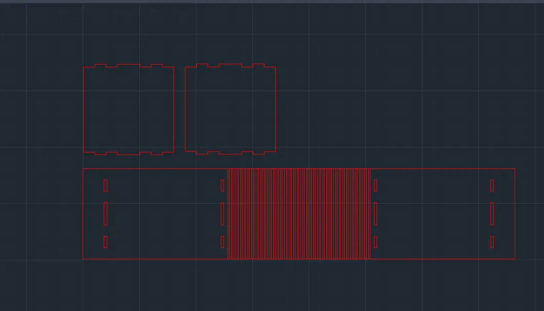
Note: You will notice that this designed uses a lot of lines for the kerf bending section. This was because my calculations where wrong at the beginning. The formulas explained above are the correct ones.
In order to join our supporting bases I went for a mortise and tenor pattern. The tenor part was made 1mm bigger in size in order to better accommodate for the actual cutting. In the end I ended up with this amount of supporting bases:
- 2 small supporting bases to the sides (the ones already shown).
- 1 big supporting base in the back of the stand, with some cable holes.
- 2 small supporting columns for the front, to serve as both extra support and style.
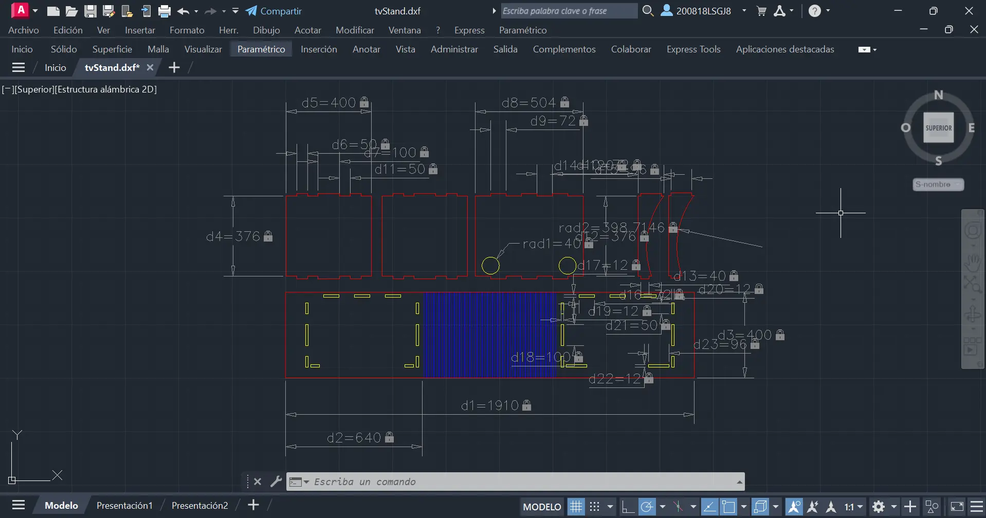
At last, I created 3 separate layers for each type of cut:
- A red “profile” layer for the outside of each piece.
- A blue “kerf bending” layer for the kerf bending cuts.
- A yellow “inner” layer for everything that will be cut in the inside of a piece.
I also made some annotations on every key dimension of the build. It´s not meant to be pretty, is meant to be a record of my sizes for future recalculations and reproduction of the piece.
Aspire
The CNC Router itself is not able to interpret .DXF or .SVG files itself. You need to convert your design into GCODE, which is a series of steps the Router will read. it´s like telling it exactly how much steps to take in any direction and in what order. AutoCAD cannot export our design in GCODE, but luckily for us there are programs that will not only help us to create this needed file, but also prepare our design for the cutter.
Aspire Vectric is a CNC modeling software, designed to help you create, prepare and visualice anything you want to cut with your Router. To use Aspire, you can download it´s free version from their official page. The free version is enough to do almost anything we need to do, but there is one big step we cannot do with this version, more on that later.
Opening Aspire for the first time, we must create a new file. Once in our new file, the program will ask us some key values of our project in the left side of our screen:
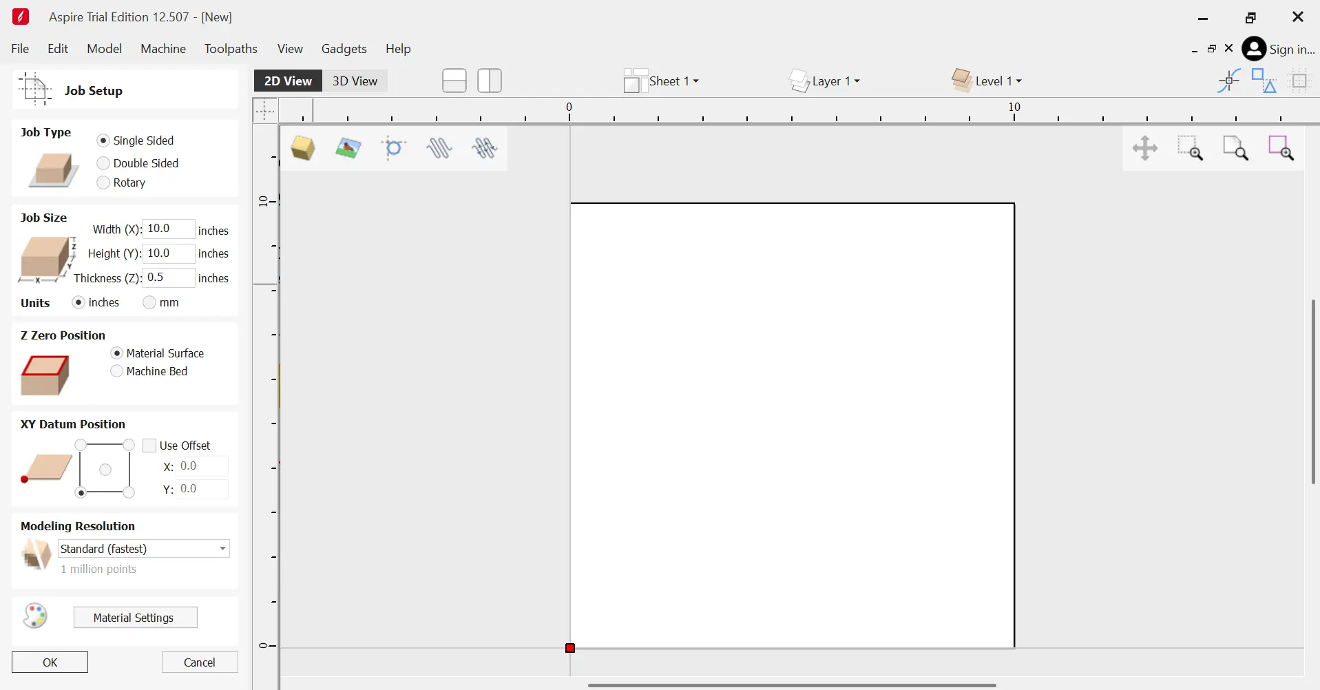
For my specific project, I selected the following parameters:
- A Single Sided job type.
- 122mm Width and 240mm Height.
- Material Surface as Z Zero.
- Bottom Left corner as XY bottom.
Now, in Files > Import as Vector… we can import our .DXF file from AutoCAD:
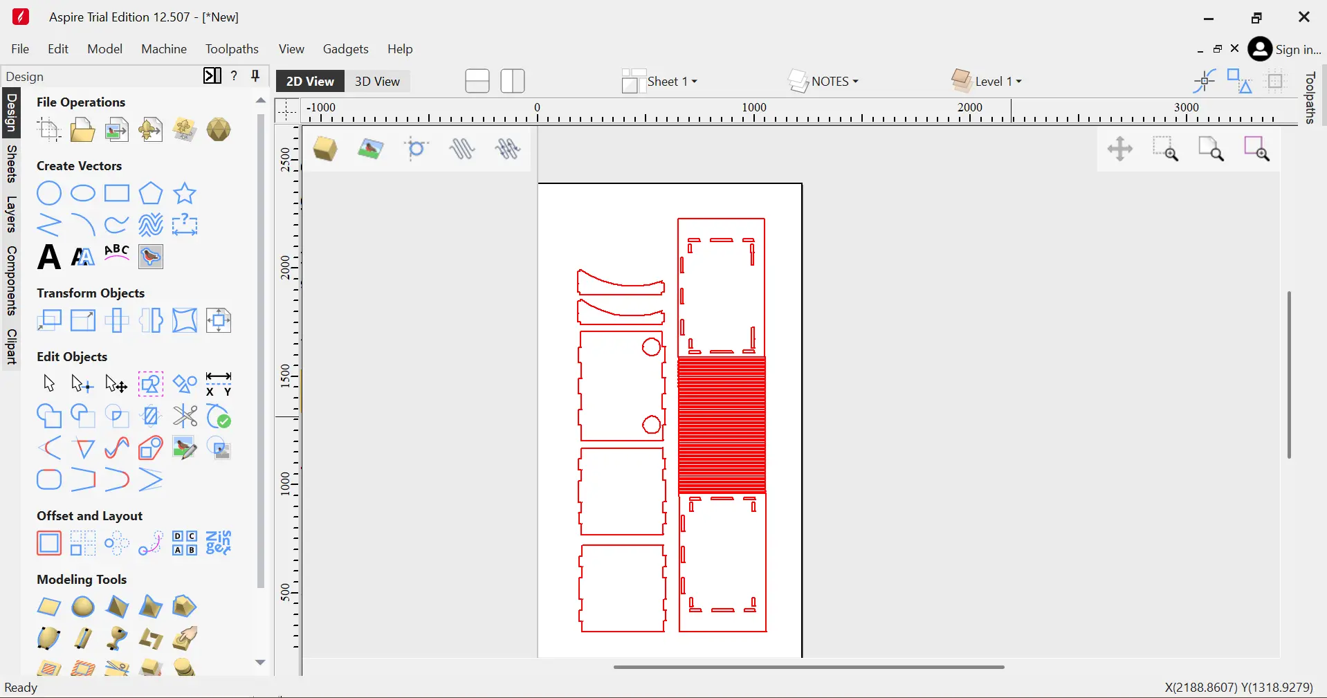
Now, we can change tabs by closing the Design menu on the left side of the screen and opening the Tool-paths menu on the right side of the screen.
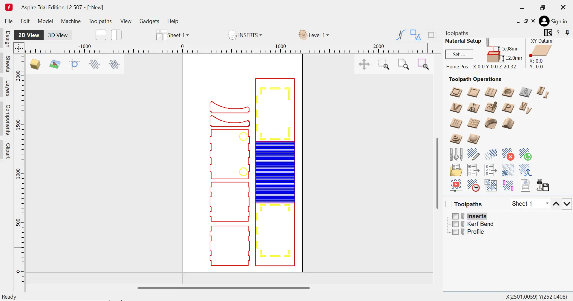
We must select the “Profile Path” option (the very first icon) and configure our 3 types of cut: The profile, the “indents” and the kerf bending. To do this, we can simply select the “Profile Path” option:
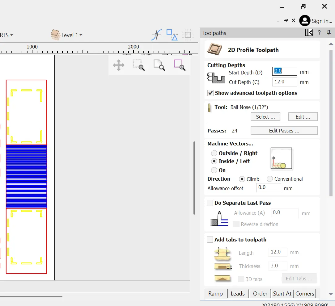
A menu will appear with multiple options. The first thing wee must select is the actual path. To to this, go to the “Select…” button and choose your desired layer. Make sure to select “Closed” or “Opened” vectors as they apply, and the “Associate with toolpath”. Now, we can configure the rest of our path:
For the “profile” layer I went with:
- Default Cutting depth (12mm).
- 1/4" Standard Mill Tool.
- Machine Vectors on the Outside.
- Added Tabs (Selecting the “Add tabs” menu, Edit Tabs > Generate Tabs).
For the “Indent” layer, everything stayed the same, except:
- Machine vectors on the Inside.
And for the “Kerf bending” layer, I went with:
- 10mm Cut Depth.
- 1/4" Standard Mill Tool.
- Machine Vectors On.
- No Tabs.
Note: This setting are not the norm, and you can experiment with them.
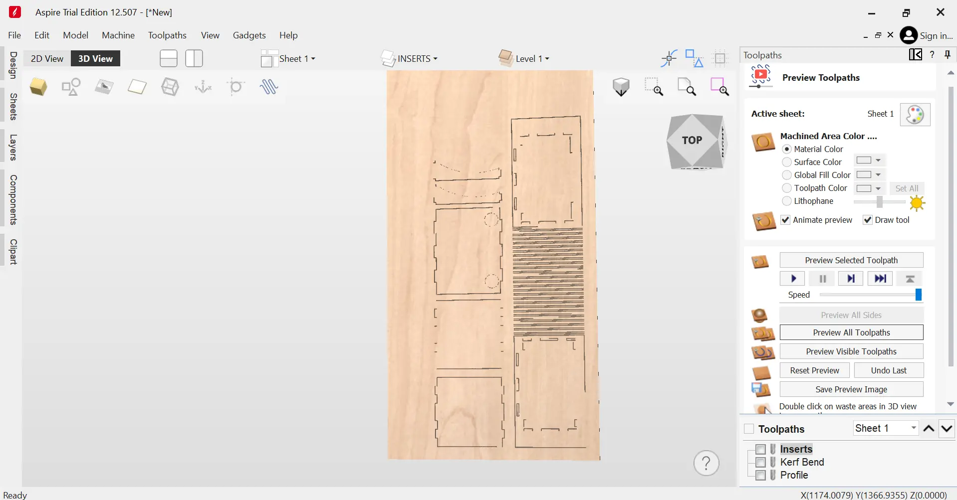
After that, a 3D preview of your cut will appear in screen. if everything seems correct, click the “Close” button on the “Preview Toolpaths” menu.
Now we face a big problem. This last step involves exporting our Paths into the GCODE for our CNC Router Model. Sadly, the free trial version of Aspire won´t allow us to export GCODE, meaning that our design cannot be completed using only this software.
VCarve Pro
In our Lab and some computers on our university, there is a software called VCarve Pro that will solve our problem. VCarve Pro is the exact same software as Aspire, but without 3D rendering capabilities. Once our design is completed in Aspire, we can easily export it into one of this computers with VCarve Pro installed. To do this, go to Files > Export as… and save your project as a VCarve Project file.
Now, open your project in VCarve Pro, and export the .GCODE file. You will be asked for a CNC Router model. In your group assignment page there must be the exact name and model of your CNC Router if you are unsure. Still, your Lab´s computer should already have the Router model already available to use.
Now, with our GCODE file in an USB, we can begin using the CNC!
Using the CNC Router
Our university has two available CNC Routers: A Mach 3 and an Asia. I had to use the Mach 3, as most of my classmates wanted to use the Asia and spaces where already taken. I was already at a big miss advantage, as our Lab´s safety training and usage lesson where given on the Asia, with just a brief overview of the Mach 3. And, most importantly, I have never used a CNC Router before.
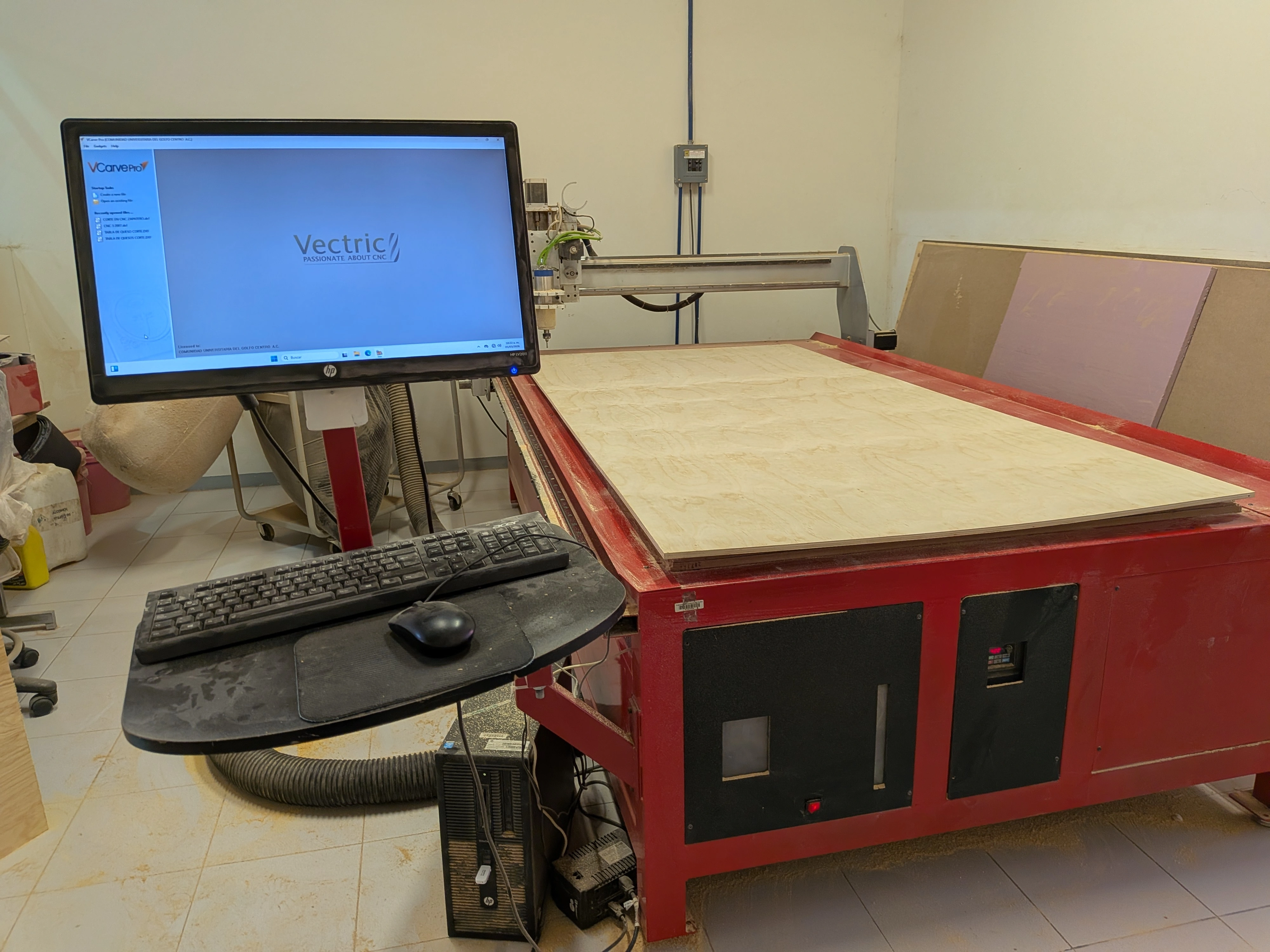
Still, the basics of using the Asia Router still applied to the Mach 3. First of all, we must start up the Router with it´s on/off switch. The Mach 3 is computer-controlled, so there is no dedicated physical emergency stop button, but this switch can be used as so in case of emergency.
Opening the Router´s software for the first time, it looks like a spacecraft. For whatever reason, the UI seems to be misplaced on this computer. Everything I needed was there, but it was disorganized. Looking at this software for the first time, it was quite intimidating…
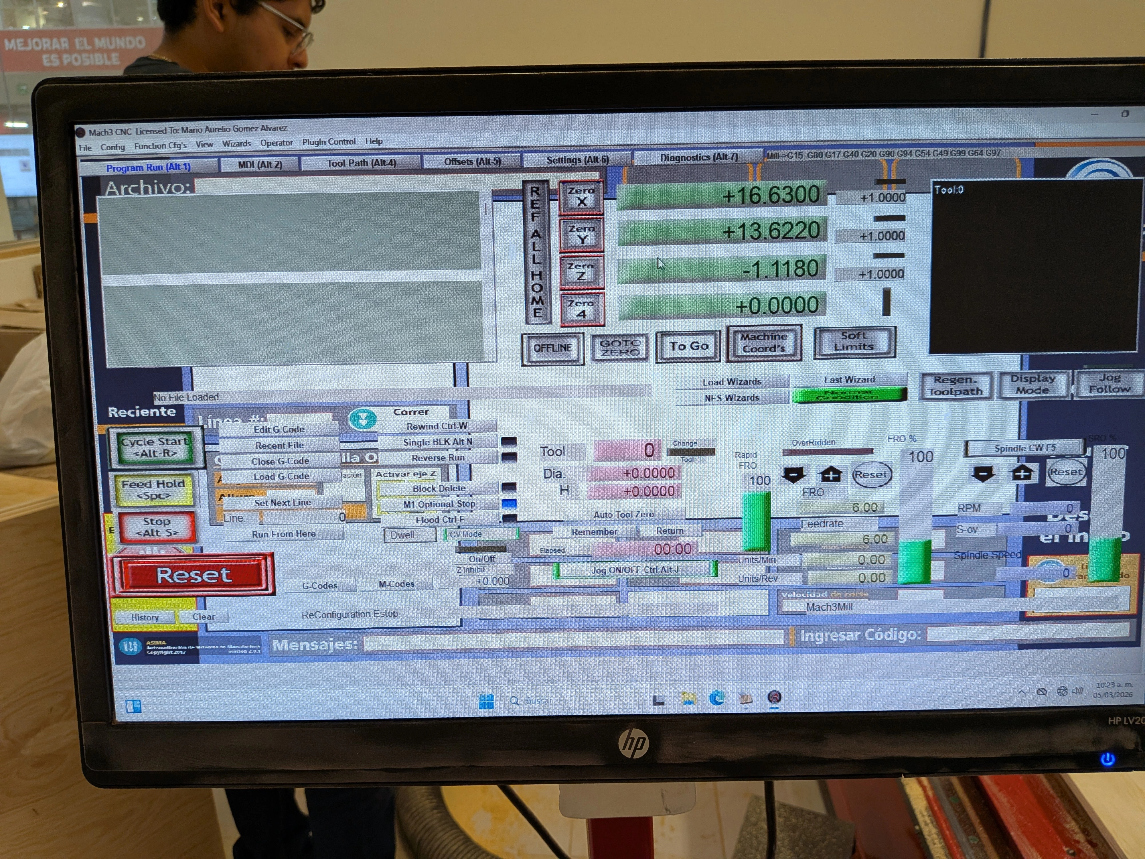
With a YouTube video I was able to identify the manual control emulator of the Router. By typing TAB on the MDI tab, you can access this control to move your Router to your desired position:
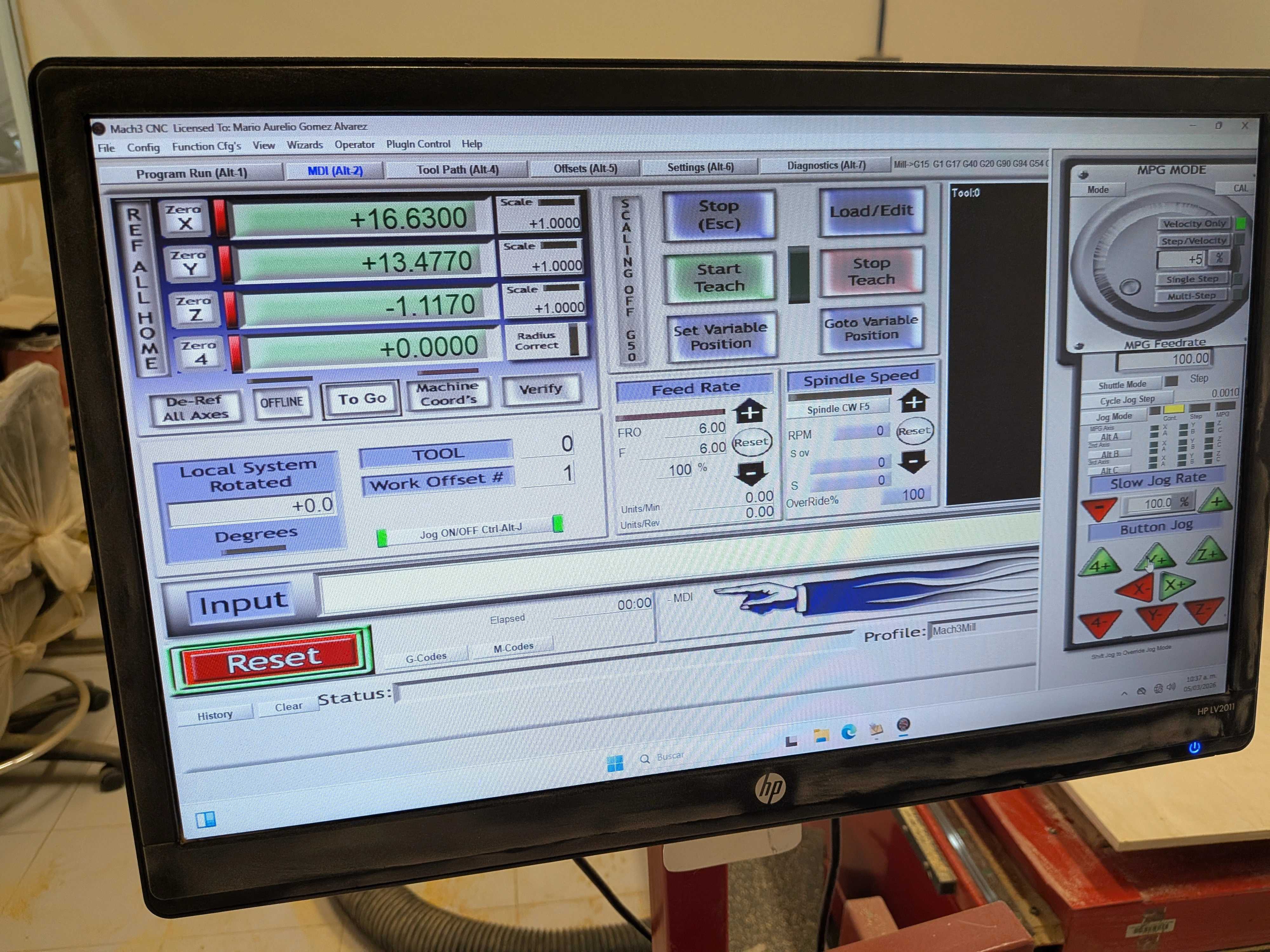
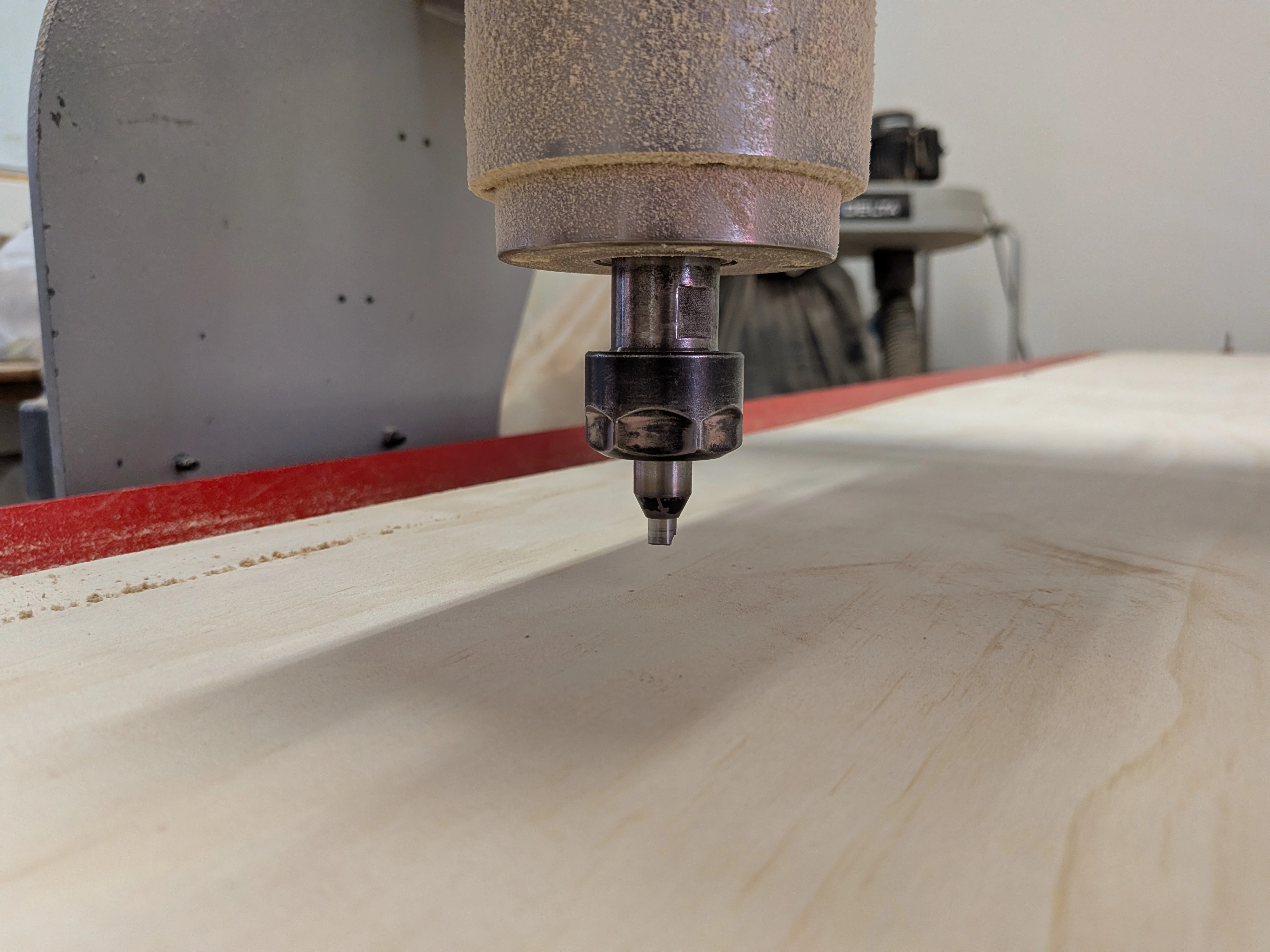
After the Router to your desired starting position, you can click the Zero buttons for each axis (x, y, z). We established that our Z Zero was going to be the material surface, so our drill bit was meant to be placed on top of the material. Using a Slow Jog rate in the controller emulator, I was able to place the drill bit right on top of the material.
Now, with our zeros ready to go, we loaded the GCODE into the software. Our design was ready to be cut! I clicked the start button. And then disaster struck…
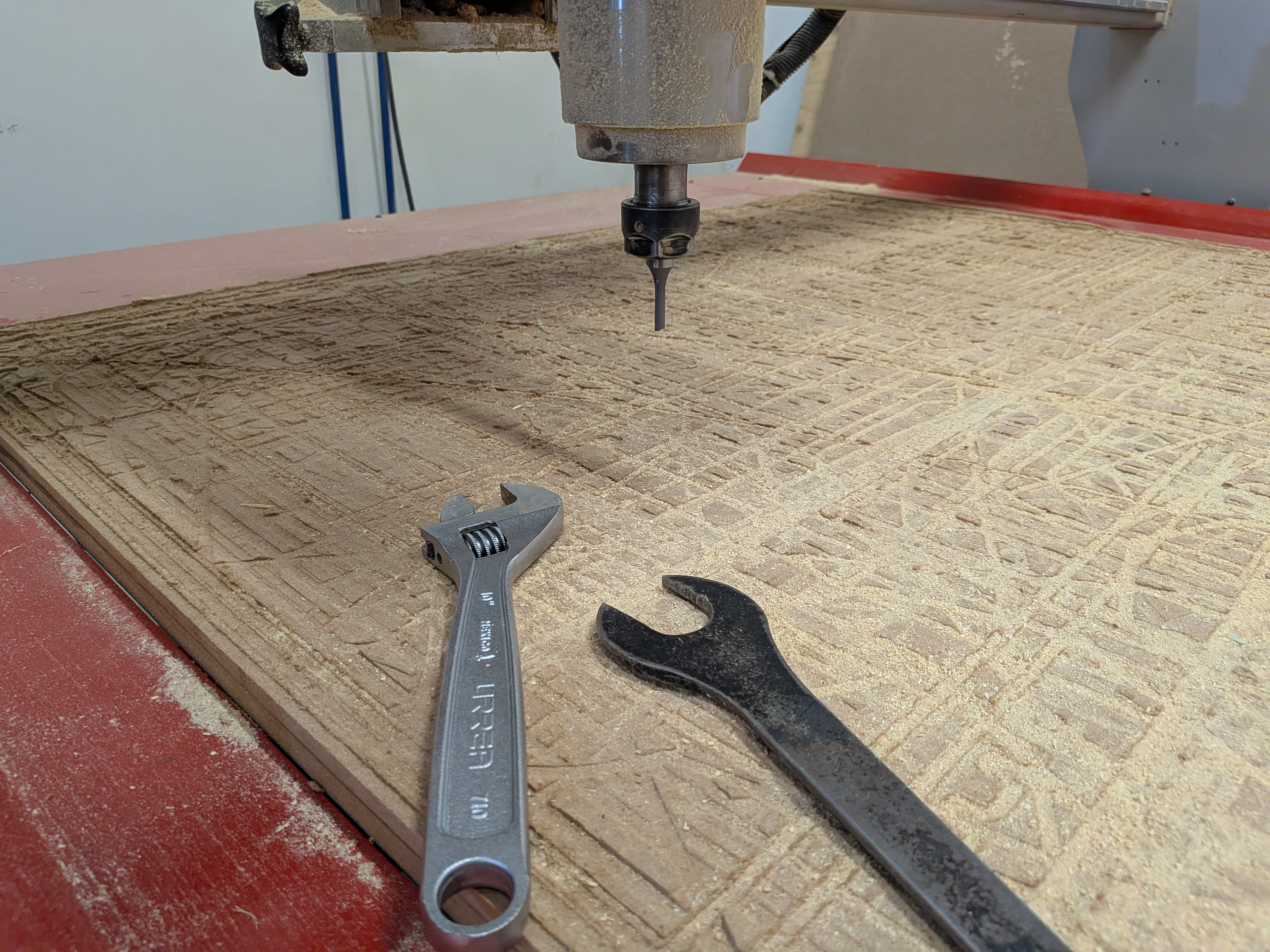
Something went Wrong…
The drill bit (without spinning) pierced itself into my plywood and then proceded to move. Even though the drill bit was stuck, the machine kept moving forward, applying pressure to it until it exploded. In a matter of 2 or 3 second, I the drill bit was broken. I wasn´t even able to react on time. By the time I hit the emergency stop button, the damage was already done.
I have a few theories on what went wrong:
- I was meant to get the drill bit to spin before starting the cutting process.
- I placed the zeroes of the machine in the wrong place.
- Something was not correctly configured in Aspire / VCarve Pro, like forgetting to add the Z Zero on the material.
It was a lack of proper training and experience plus one or many mistakes from my end that resulted in a failed attempt at using the Router. There was a spare drill bit available, which was great news for everyone else that was scheduled to use this Router, so I was tasked with replacing it. But after everything was done, my time to use the Router was over, and I wasn’t able to cut my pieces.
A Lesson on Failing
Failure is the greatest teacher. One day, some of you might encounter yourselves in a situation similar to mine. It is natural to feel upset and discouraged from the experience. In the end, the only thing broken was a replaceable drill bit. As long as no one gets hurt, life goes on. Prices are paid, pieces are replaced. And most importantly, now that we now what not to do, we can regroup and go back to the Router once again. The FAB Academy is meant to be a learning experience, and with learning comes failure. Getting up and trying again is the only way to get better at something.
Second Attempt
At the time of writing this, there are only 2-ish weeks remaining for this FAB Academy 2026. I’m just now finding time to revisit this assignment and try to finish it. Currently, only one of the two Routers available at my university is working, the one I used for my first attempt. I could have returned to this machine once again, but that came with some disadvantages:
- Usage of the machine for students is limited to active school periods. I would need to wait until the 1st of June to use the machine (its currently the 25th of May). Weekly activities are due on the 3rd of June, leaving me a really small window of opportunity to use the Router and assemble my piece (given that nothing goes wrong at any stage). Its doable, yes, but if something goes wrong, that’s it.
- I still don’t know how to operate the machine. This means that if I where to encounter any other problems (like I had on my first attempt), I would be on my own. Most of our Lab’s instructors are teachers at our university, and they use this “vacation” week for administrative work, meaning they are mostly occupied or absent from the university. It would be hard to find an instructor that can properly explain to me how to setup my files and use the machine. Again, doable, but it heavily depends on the schedule of our Lab’s instructors.
Our university offers the use of the Router as a paid service. Students can pay a fee for the machine usage, around $0.6 USD per minute of operation. Using this service will get my assignment milled for sure, but it removes me from the equation. I could still learn how the machine is operated by seeing how the machine manager works, asking and taking notes. But, I have a better solution.
My Dad’ CNC Router
Fun fact: My dad works almost daily with CNC Routers!
He’s in the private events business, and a good amount of his projects require the use of a CNC machine. This means that I not only get access to a CNC router just for myself, I also get an expert teacher to guide me through the process. Wouldn’t it be better to learn how to use the Router machines available at my university? Yes, but also no.
Learning how to operate my dad’s Router comes with a few benefits: The first one being that this machine will always be available for me to use (given that the company isn’t currently using it). The second one being that I actually get to learn how to operate the machine, instead of paying to see how its done. Finally, it solves all my timing problems, meaning that I don’t need to wait for the university’s machines to be available. The only downside is that I don’t get to fully learn how to operate our university’s Routers. But, if I’m being honest, the chances of me using the Router machine are almost null, considering that we Software Engineers don’t need to use Routers for our assignments, unlike 3D printing which can come in handy. And for that “one in a million” project I develop that requires CNC machined pieces, I get to use my dad’s Router for free. Plus, there is always the paid service, which ensures quality pieces at a fairly reasonable price.
With all that said, I waked up early for this “Bring your child to work” day.
Using The (Other) Router
Note: There are some things to keep in mind for the following part of this documentation. Most of the content will be showcased with videos, as it was more practical for me to take videos rather than photos. The operation of this machine might defer from other Router machines, but the same principles apply.
The first step is preparing my file for this new machine. For the previous Router attempt we had to use VCarve Pro to generate the gcode for the machine. For this one we will be using Autodesk ArtCam. This CAM (Computer-Assisted Manufacturing) software works pretty similarly to VCarve, with a similar workflow:
- Setup the material’s width, height and length.
- Load the DXF file.
- Setup the tool paths.
- Export.
We setup the material with the exact same dimensions of the Aspire/VCarve Pro setup. The toolpath chosen was basically the same, with an outer cut, inner cuts and the kerf bending cuts. The only thing that changed was the drill bit type, as it was a different size from the one on my university’s Routers.
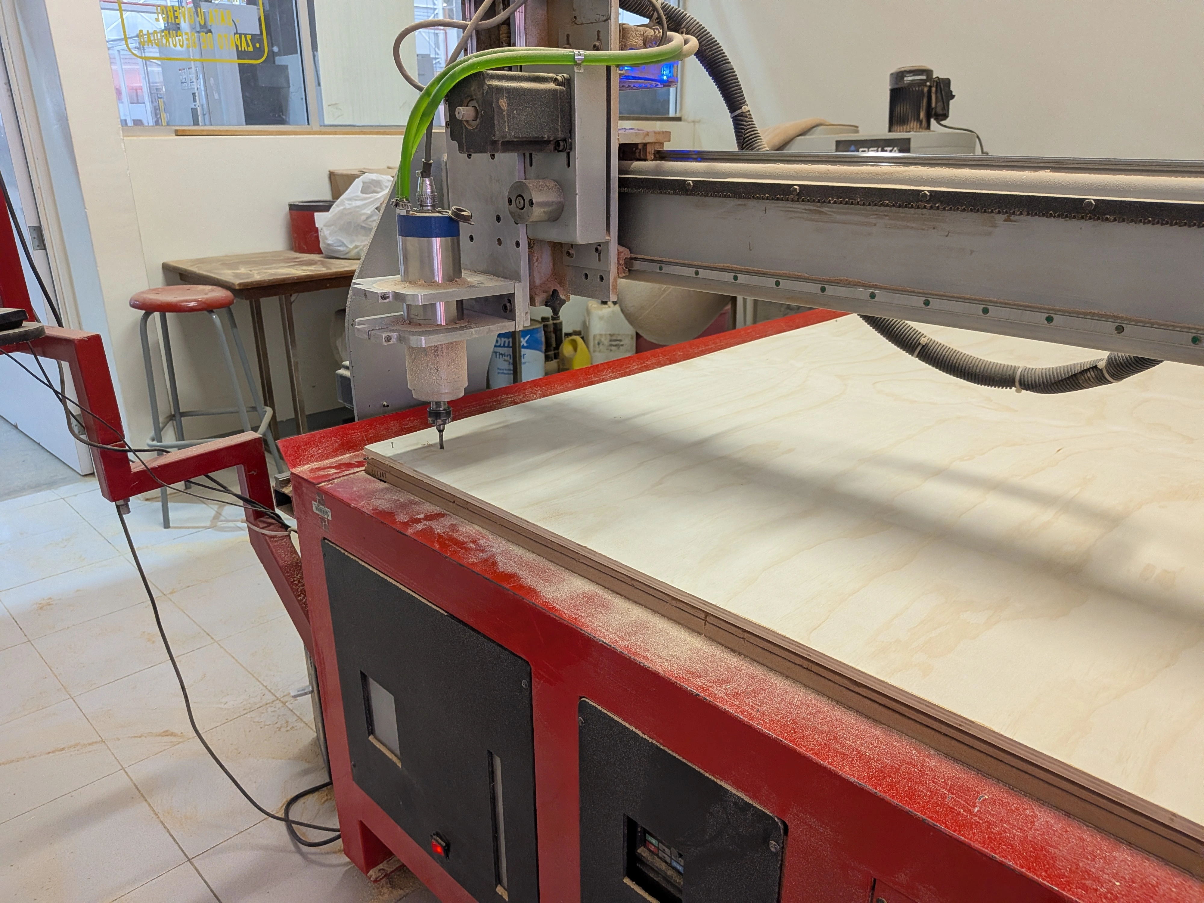
Now, with the file ready to go, its time to set up the machine. We need to fix the plywood into the Route’s bed. To do this, we will be drilling the plywood into the bed.
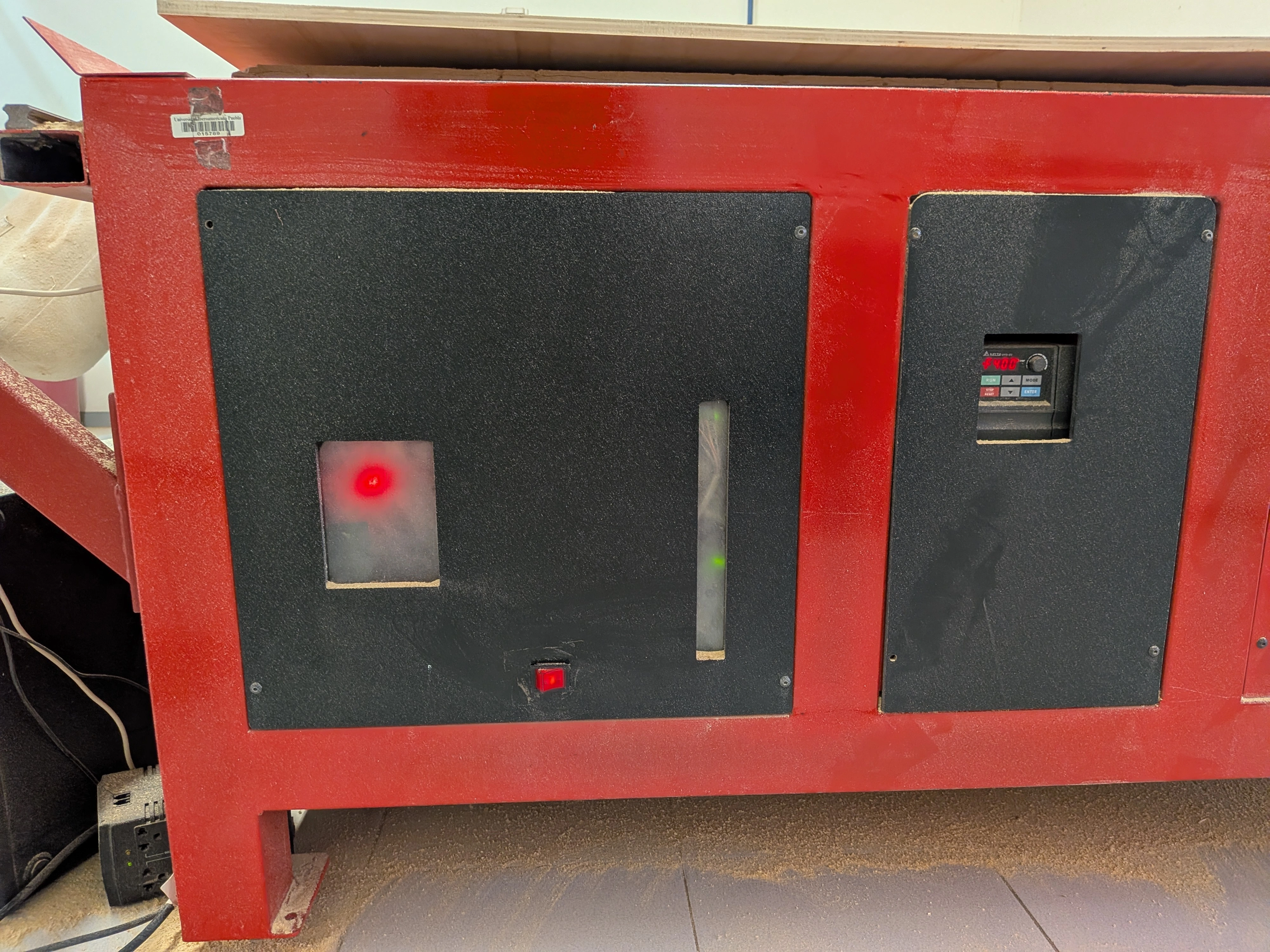
Now we will take control of the machine. The Router from my university that I used needed a software to control everything. This software was quite complex to understand, unlike the second router on my university which was controlled with a built in controller. This new Router had the same type of controller, where you can move the Router spindle on its X, Y and Z axis and set their zero values. Using the controller we set up the zero values of the machine.
Now, it was just a matter of starting the machine with the controllers “start” button. The machine started working without issues. The machine’s room has a camera mostly used for monitoring ongoing works. We took the video of our work to create this time lapse.
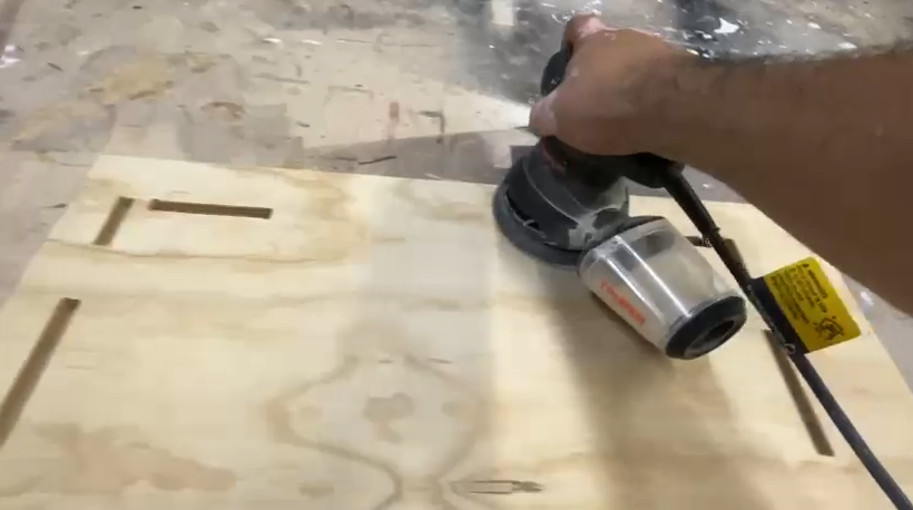
Post Processing
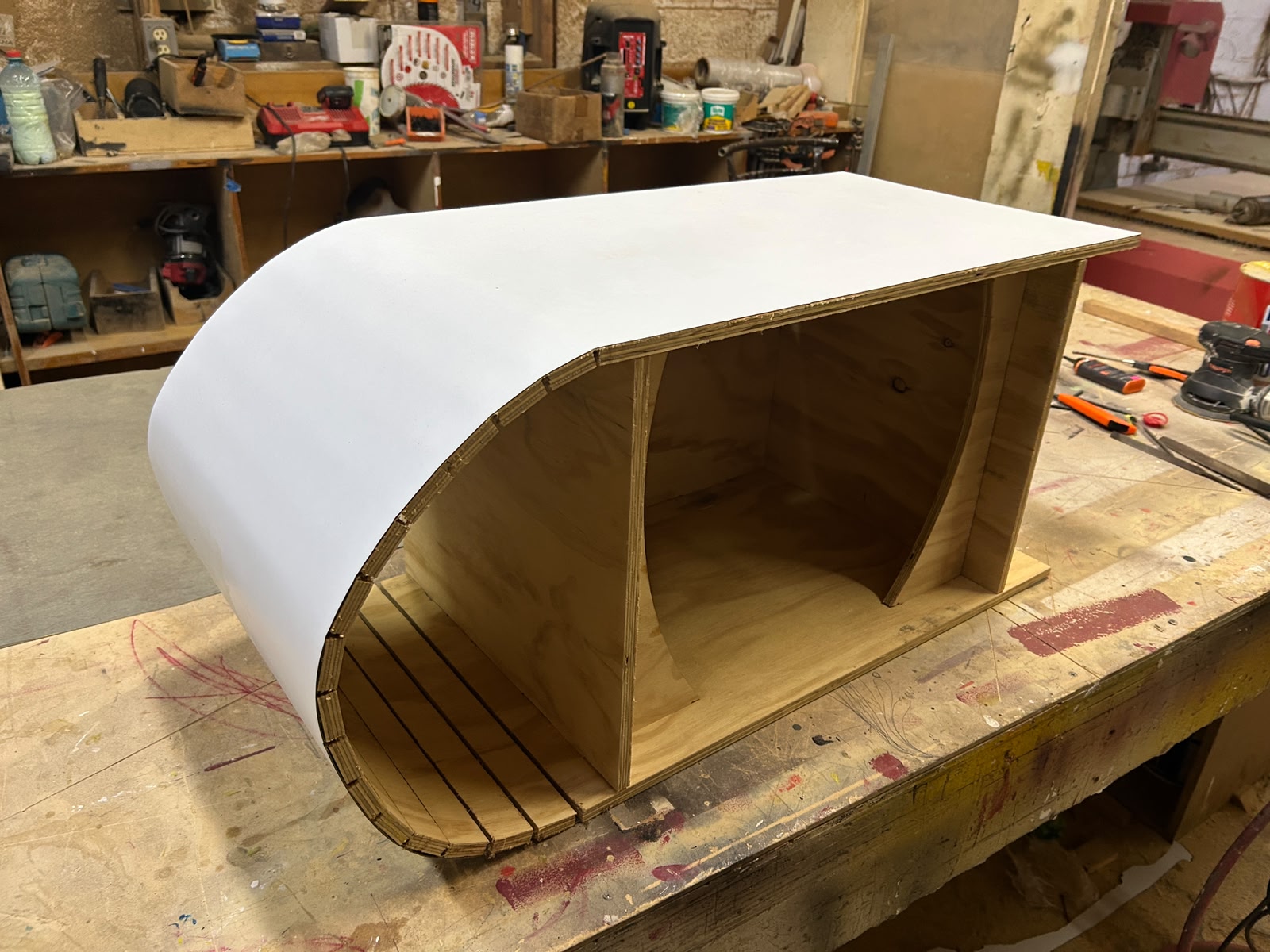
We decided to sand the final pieces before putting them together. This step was not necessary (I wasn’t even considering it). But my dad insisted. He showed me how to use the sanding machine, and then I finished the job myself. Sanding with a sanding machine is quite easy, it was enough with just a 150 sand paper. After that it was time for the kerf bending part. The method I researched involved soaking the “to bend” part with warm water, or water plus light heath from a heat gun or hair drier, and then slowly bring it to shape and holding it down with clamps. I though this process was going to be the hardest part, but surprisingly it wasn’t. It turns out that the tutorial I watched used another type of wood. Plywood was really maleable once soaked in warm water. This is probably because of the fiber arrangement of plywood.
After this, it was just a matter of putting together the pieces to build my final TV stand. My calculations and design was spot on, and my pieces fit together without issues. I just added some wood glue so that everything stayed together nicely. And after letting it dry for a while, the TV stand was ready!
The Bottom Line
I wrote all this section of the page the day after finishing my TV stand. I am just noticing that I took no photos of me actually working on the project. It was a mistake on my part, I was so focused on putting attention and recording everything I could that in no point I thought of asking for photos of me working. This week’s assignment turned out to be the “hardest” out of every assignment. Not necessarily because using Router machines is inherently hard, but because of everything that happened:
- Having to learn and use a new machine for the first time.
- The broken drill bit
- The second router being unavailable because of a malfunction (which to this day hasn’t been fixed)
- The fast nature of the FAB Academy requiring me to put this assignment on hold to not hinder my progress.
This might have not been the ideal conditions for me to complete this week’s assignment the best way possible. I know that, even if I accomplished the assignment with my dad, the ideal scenario was for me to do it on my own in the available machines in my university. Regardless, in the end, I learned how to operate a Router machine, plus designing big things in 2D CAD software. Hopefully I can have time in the future to learn how to correctly operate the Router machines of my university.
Finally, I want to thank my dad. Not only for helping me with this assignment, but also for supporting me throughout this FAB Academy 2026. Thanks to him I had the wonderful opportunity of taking part in this course. ¡Gracias papá!