Computer Controlled Cutting
Computer Controlled Cutting (CCC from now on), is the act of using machines to trace out designs in material like wood, plastic or even metal. Instead of having making every cut yourself, which is not only hard but not precise, machines uses lasers or water pressure to make those cuts and engraves for us, following directions we give them. CCC saves us the time and effort while also giving us precision and versatility.
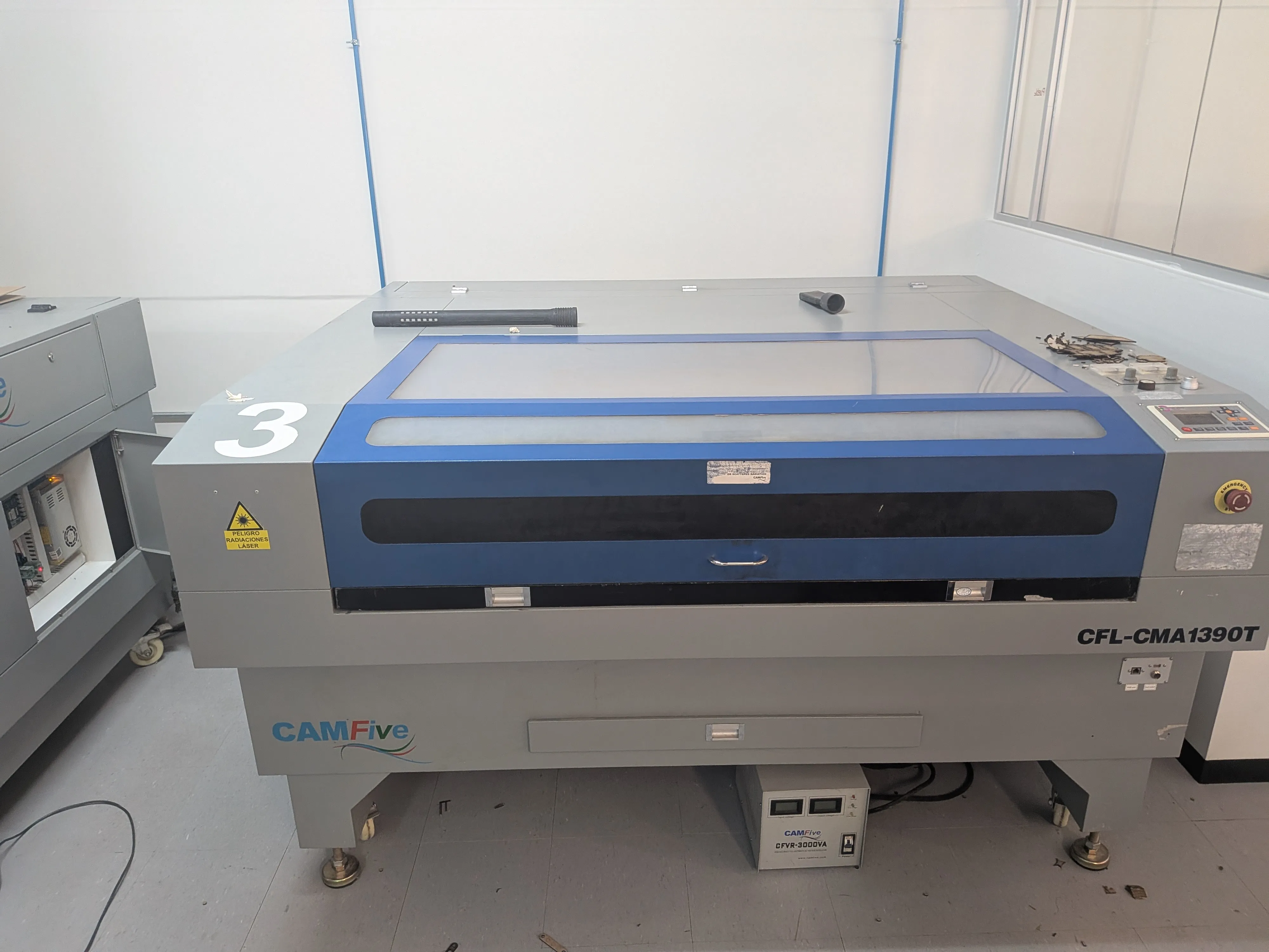
For more information on how to use a Laser Cutter, check out our Lab’s Group Assignment Page. From this assignemt I learned the different Laser Cutter Router models available to us in our University. I learned about how this machines operate, its key components and safety considerations when using them. This page also taught us the basic parameters to be configured on the machine, how to calculate the kerf value of each machine and how the main application to controll it works.
Creating a Cutting File
To create a cutting file you need a CAD software capable of two things:
- Drawing with vectors.
- Exporting a document as .dwg or .dxf.
Some software that meet this criteria are, but not limited to:
- Adobe Illustrator
- Inkscape
- AutoCAD
- Affinity
Your software selection depends on preferences. Personally, I decided to go with AutoCAD, because I liked its way of "accuracy-driven" work and in the previous week I got to toy with it a bit. If I had no Autodesk licence, I would have gone with Inkscape.
Before even opening any CAD software, I first decided to sketch on paper what i wanted to design (A practice I´ve been adopting recently). Before this week I knew I wanted to work with 3mm MDF as it is cheap and versatile, ideal for a beginner project like mine. With my material chosen, I decided to sketch a laptop cooler stand.
Some of my idea´s features include venting cuts to help my laptops cooling capabilities (as it has venting holes on the bottom), 10° angled inclination for both the cooling and hand resting ergonomics (I like to work in slightly inclined keyboards). And I decided to add a phone stand to it´s side (not in the sketch, the idea came on later).
I liked this idea because it features:
- An assembled final piece with slots and tabs.
- Vast space for text and image engraving.
- A variety of shapes and techniques involved.
With the idea ready on paper, now we can open a new AutoCAD file and get going
AutoCAD for Laser Cutting
In my personal experience, AutoCAD excels at 2D technical drawing, which is great when exact measurements are a must, specially with modular models like mine with pieces that come together. Everything you draw in AutoCAD has a measure. This makes it's workflow a little bit slower than other software, as you must manually input your lines and figure's size. In return, you get a 2D file you know will be cut exactly as you wanted.
Before we start drawing there are some preparation steps. Laser cutters guide themselves with the color of your lines in your to-cut file. The color convention is red for fully-cut lines and black or blue for engravings. This colors may change with your laser cutter's software.
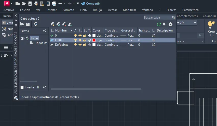
To create this color coded lines, we must create layers. To do this:
- Type "LAYER" in your command pallet, or in any blank space in your workspace. A window will appear.
- Select the "New layer" button (the one with the sun).
- Name your layer "CUTTING" (name not strict), and set the color to red.
- Create a new "ENGRAVING" layer and set the color to black.
Create one last "MEASURMENTS" layer and set the color to white. This layer will be used later.
Note: Your AutoCAD app might be in another language, and your commands might be named differently. It translating the commands is an issue, just add an underscore (" _ ") before your command. AutoCAD will detect the command correctly.
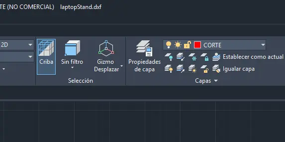
Now, in your main menu, go to the layer tools and select your cutting layer. Whatever we draw now will be cut once we export the file. To change layer, you can do it the same way. If for any reason you've mistakenly drew something in a wrong layer, select it and then change your layer. The object line color will change, indicating the object it's now in the desired layer.
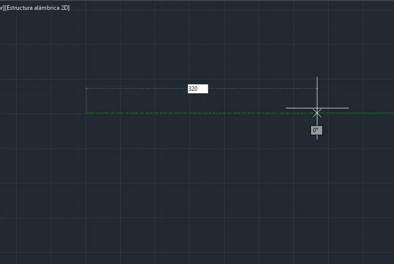
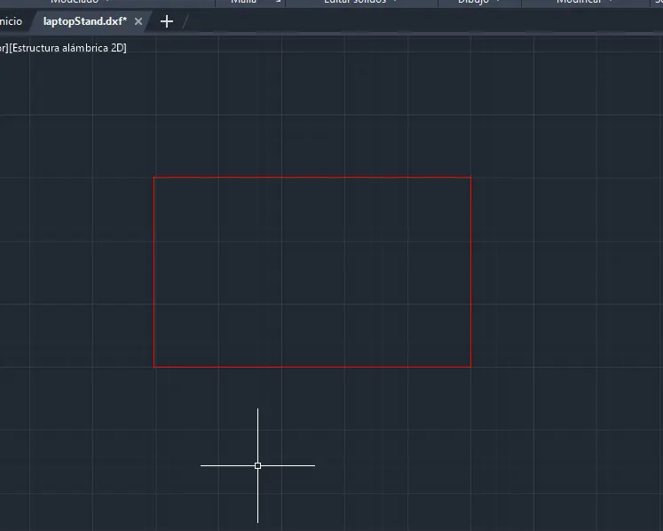
We can begin by drawing our first shapes. I heavily recommend using the line tools for most of your work, as it gives you the most control over what you are drawing. To correctly use lines:
- Type "L" in your command pallet, or in any blank space in your workspace.
- Select a starting point for your line.
- Extend your line to your desired direction, then write your line's exact measurement.
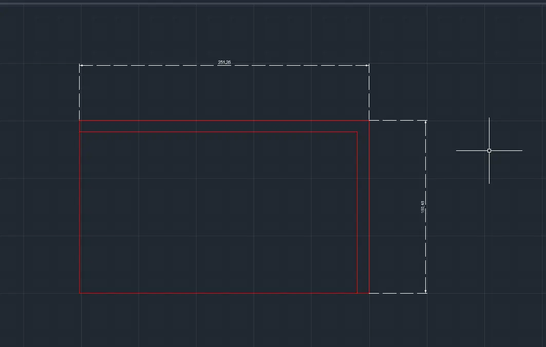
With simple lines we can create our very fist figures, like a rectangle:
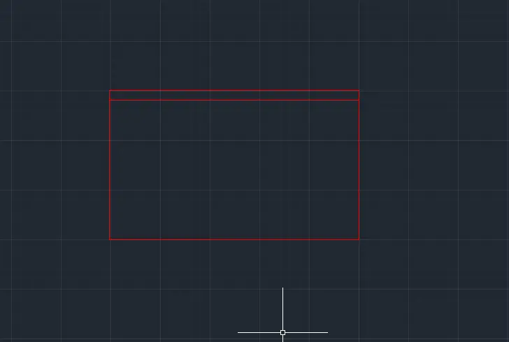
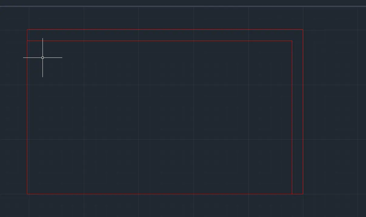
Now it's time to showcase a new tool that will help us make new lines parallel to existing lines and with a set distance. To use the Offset tool:
- Type "EQ" in the command pallet, this is the shortcut of the tool.
- Type the distance your new line will have from the original and press ENTER.
- Click on the original line.
- Drag your mouse towards the direction of your new line and click.
- Your new line is now created!
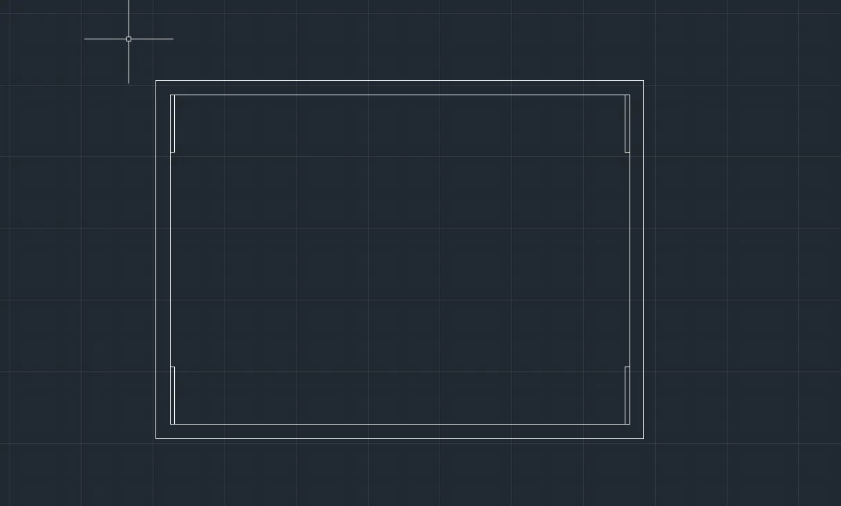
Another useful tool we will be using a lot is the Trim tool. This tool is the scissor icon in the Modify tab. With this, we can select individual lines to erase. This is the most important tool when cleaning our drawing of not needed lines. To use it:
- Select the TRIM icon in the Modify menu.
- Select the line you want to erase. You can also click and draw to select multiple lines to erase.
- And you are done!
With lines, offsets and trims, you can draw most of your symmetrical needs. This tools are more than enough to make our first sketches. In this case, I've already sketched the base plate of my laptop stand. My main technique was creating offset lines at my desired length, with other lines as guide, then trim the not needed lines.
Dimensions
For documentation sake, drawing your model's sizes in your file is necesarry. This way someone else can look at your file and understand it's shape and size. Drawing this dimensions in AutoCAD is really easy:
- Go to the "Annotate" menu.
- Select the "Dimension" tool.
- Go to your desired line and click it.
- You can now drag the annotation to your desired lenght.
Main Base
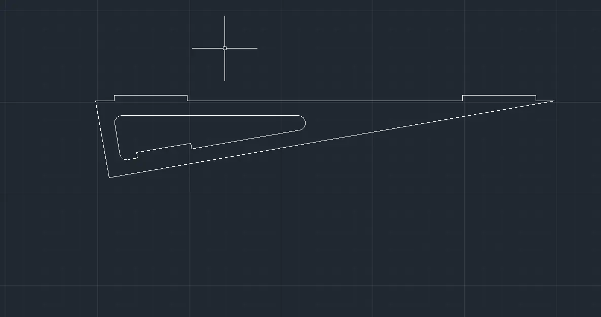
With all this knowledge, it only took one more command to get to a decent sketch. This command was the "Divide" command. By typing DIV in the command pallet, selecting a line and introducing your divisions number, points will be created in your line, from which you can extend other lines. I used this method with some temporary lines to create the ventilation slots of the main plate:
Note: Don't mind the line color, this sketch was made way before I knew about layers.
Supporting Base
With the main plate sketched, it's now time to do the supporting bases. This piece involves some new tools that will also be necessary for the rest of our sketch.
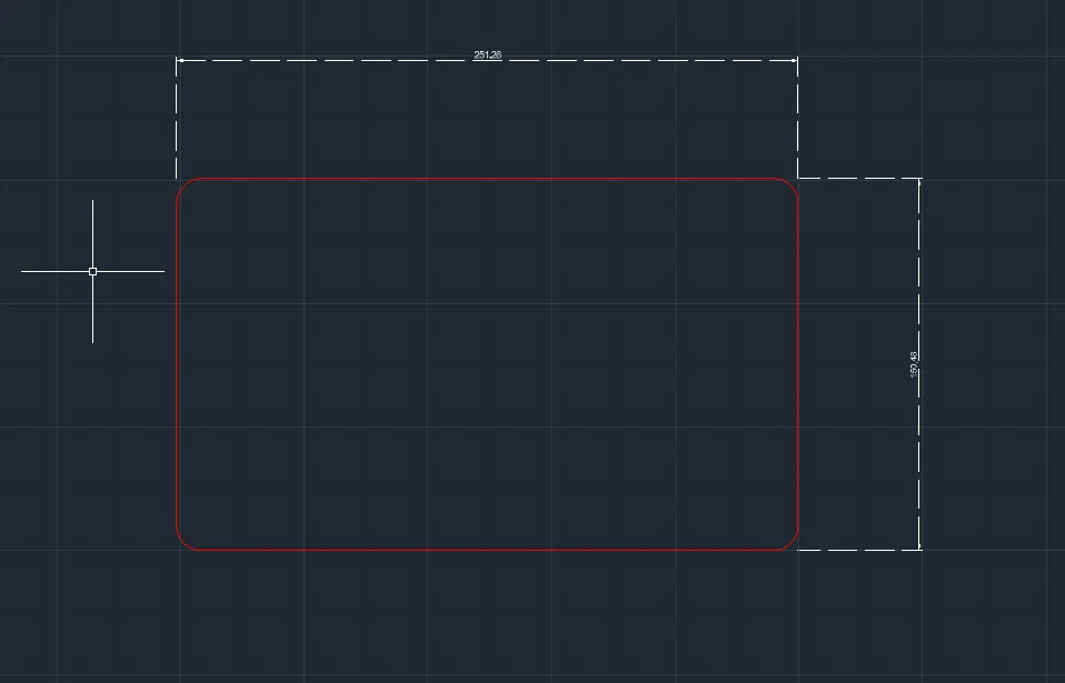
The first tool is the "Join" command. By selecting any number of coinciding lines and typing JOIN in the command pallet, all those lines will merge into a single object. This will be useful for our next and final tool, the "Fillet" tool. this tool will make edges rounder. To use the tool:
- Type "FILLET" in the command pallet.
- Type "P" inmideatly.
- Type "R" and then type your border radius.
- Select your object. All corners will appear rounded. Single lines won't be rounded, that's why we first need to join lines with the "JOIN" command to create edges.
- And you are done!
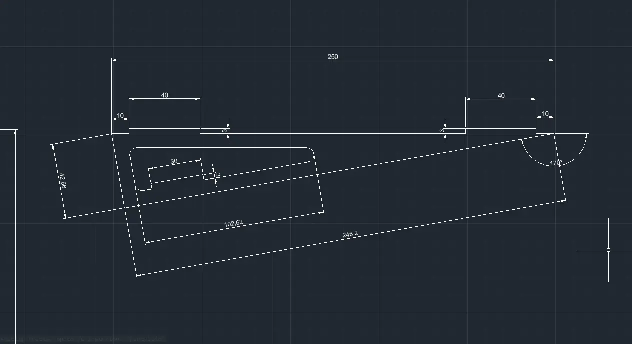
This tools helped me create this sketch of a supporting base piece, with it's corresponding measurements:
The Full Build
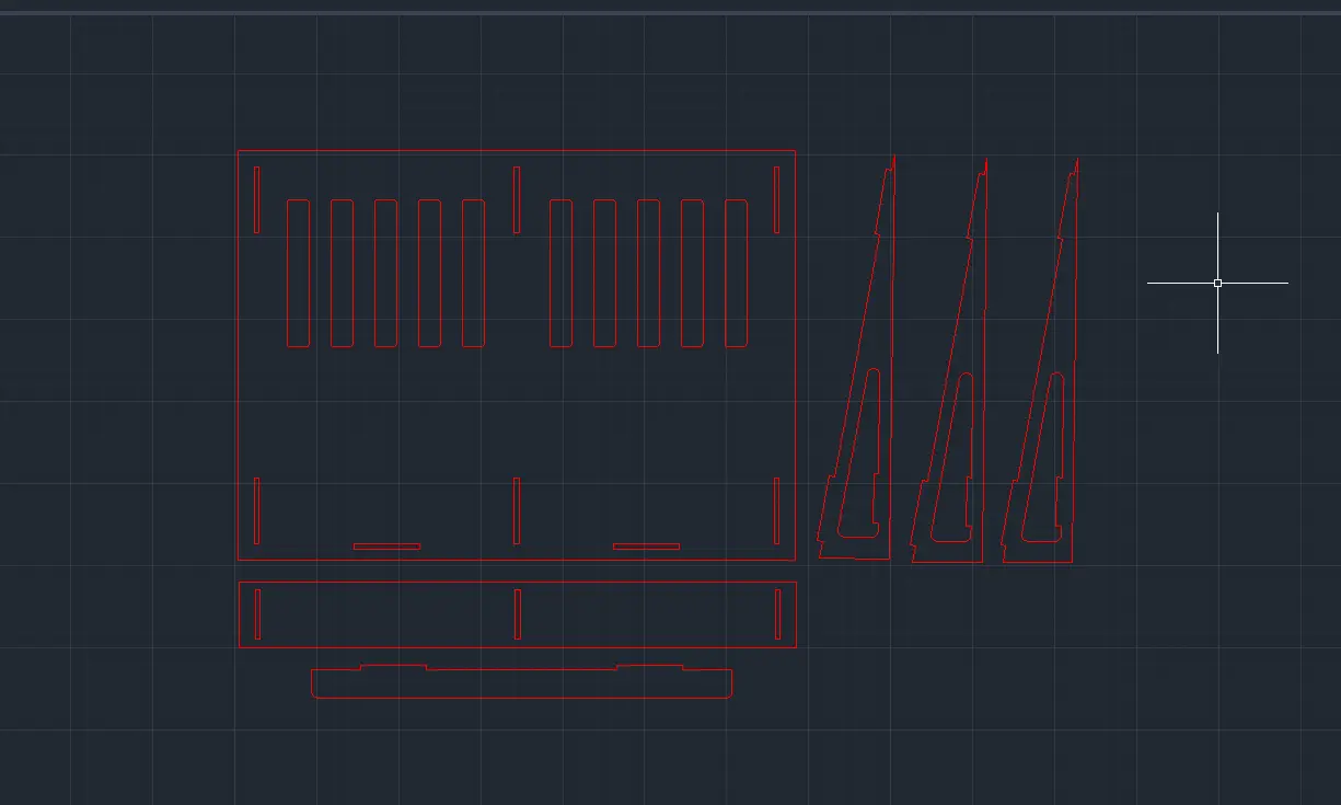
With only a few tutorials, and a few hours of work, I was able to sketch the main pieces of my final build:
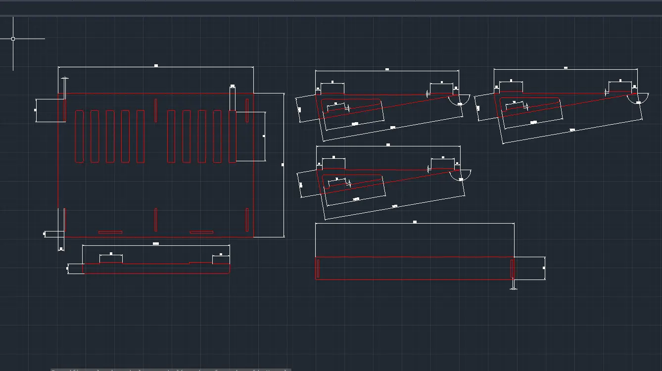
Here is a rundown of every piece.
- The biggest piece is the main plate. Here is where the laptop will rest.
- The thin long piece underneath the main plate is the supporting rod for the laptop. This piece prevents the laptop from sliding down.
- The three identical triangle pieces are the supporting pieces: Two for the sides and one for the middle of the base. This pieces will hold the angle and support the laptop.
- The long rectangular piece underneath the supporting pieces is a holding piece for this supporting pieces. It's the backbone that will hold them in place.
The original AutoCAD file will contain every mentarme for you to look and recreate for yourselves.
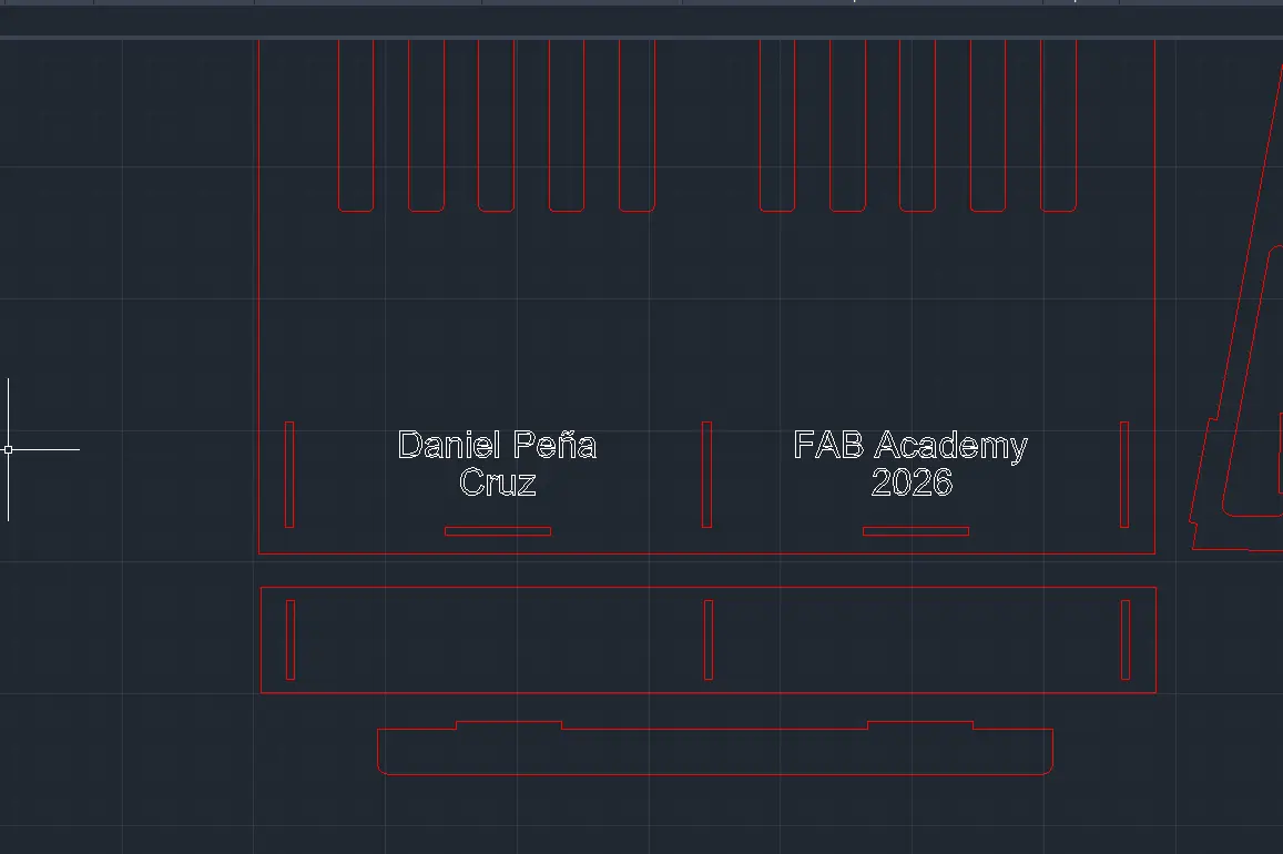
Engraving
It's really easy to engrave something like text into your piece. To do this, make sure you are in your "ENGRAVING" layer. Once in your layer:
- Type "TEXT" in the command pallet.
- Click and drag to select your text area.
- Your menu will change, showing you the standard text tools. To resise use the "Height" value and change it. For anything else, use the standard text tools.
- Once your text is ready, click your workspace.
- And you are done!
Preparing for the Laser Cutter
I recommend duplicating your file: one for measurements and one optimized for cutting. Once in your cutting file, the first step is to hide our measurements. To do this, navigate to your Layers menu, and select the drop down layer menu. Make sure you are not currently in the "Measurement" layer. Once the drop down menu shows, click the "Sun Icon" besides the layer. This will hide every item in the layer.
Next, rearange your pieces in a way they take the least space possible. This is done to save material. Keep in mind though, there must be a separation between pieces of at least 3mm. this will ensure the laser cutter won't overlap it's cut.
With your file ready, go to the "FILE" menu and click export. You can now export your file as .dwg. You can also click "Save as" in the same menu to save your file as dxf. Check your FAB Lab's machines for the best file to export as.
We are now ready to use the Laser Cutter!
Making a Parametric Kit
For this week´s assignment we had to create a parametric kit we could laser cut. This parametric kit consists on shapes that can be arranged into different shapes, sort of like a lego. This shapes will have to be created 100% parametric, meaning that with a simple value change, the whole design changes.
I initially wanted to create something similar to a toy I used to play with when I was little called "Magnetix".
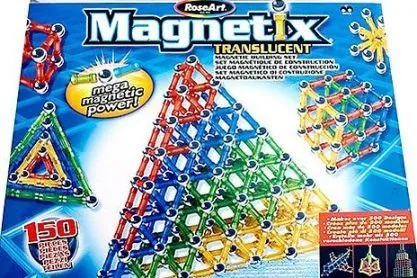
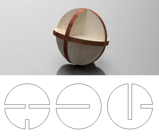
This toy consisted of ball, rod and geometrical shaped magnets that came together to create structures. I wanted to create something similar, using assembled 3D balls and rods to create shapes. In the end I decided to stay with just the balls. I followed this exact schematic I found this free 3D sphere model online, my plan was to replicate it, adding it some slots for the pieces to assemble.
(Failing at) Parametric AutoCAD
With my newly acquired AutoCAD knowledge I tried to build my parametric kit from scratch. The idea was simple: Modeling all the needed parts to assemble a 3D sphere, scale each part to have 3 different sizes (small, medium, big), and copy/paste each trio of pieces as many times as desired to complete the kit.
For starters, I had to learn the basics on parametric design in AutoCAD. This new functions are the key to making models that change shape when needed. First of, I took a look at the Parameters tab. In this tab you can create "variables" with mathematical expression, that can later be used in your model to declare sizes or relationships.
To create a new variable:
- Write PARAMETERS on you command pallet. A new window will appear.
- In this new window, click the "New user parameter" button (the fx with a sun simbol).
- After this, give your variable a name, under the "name" column, and a value unther the "expression" column.
- And you are done!
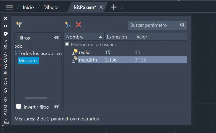
In this instance, I created two initial variables: "Radius", for the sphere faces's radius, and "matGirth", for the materials girth. This last variables is the most important as it will help us change material at any time. As we are planning on using MDF 3mm, we set it to 3mm.
Mistake #1: I forgot to add a "kerf" parameter to compensate for our Lab laser's kerf
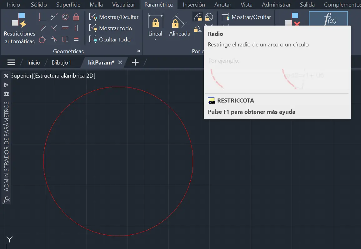
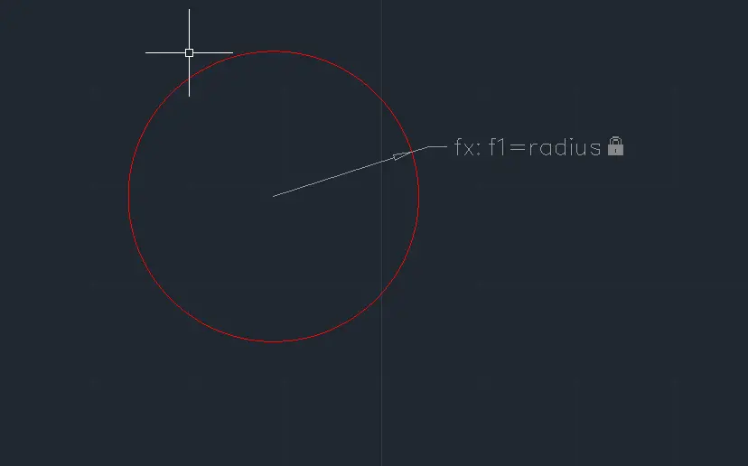
Now, we create a circle. What size? It doen't matter right now, we are about to give it a definite size. Now, navigate to the "Parametric" tab. We will be using this tools to make all of our parametric declarations. For startes, clic the "Radius" tool in the parametric tab.
Now select your circle. You will be ask to place your parametric label somewhere you want. After this, a text box will appear. after the "=" mark, write your variable name, in this case "radius".
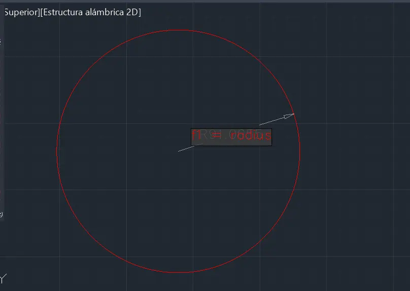
And you are done! A label will appear with your parameter. You will also note that your shape probably changed size. From now on, this circle's size is immutable.
The same process can be repeated with a rectangle. Declaring the layout of a rectangle can be tedious, but we can do it automatically with the "Auto Restriction" tool. To use it, select your rectangle and click the tool in the "geometric" tab. And you are done!
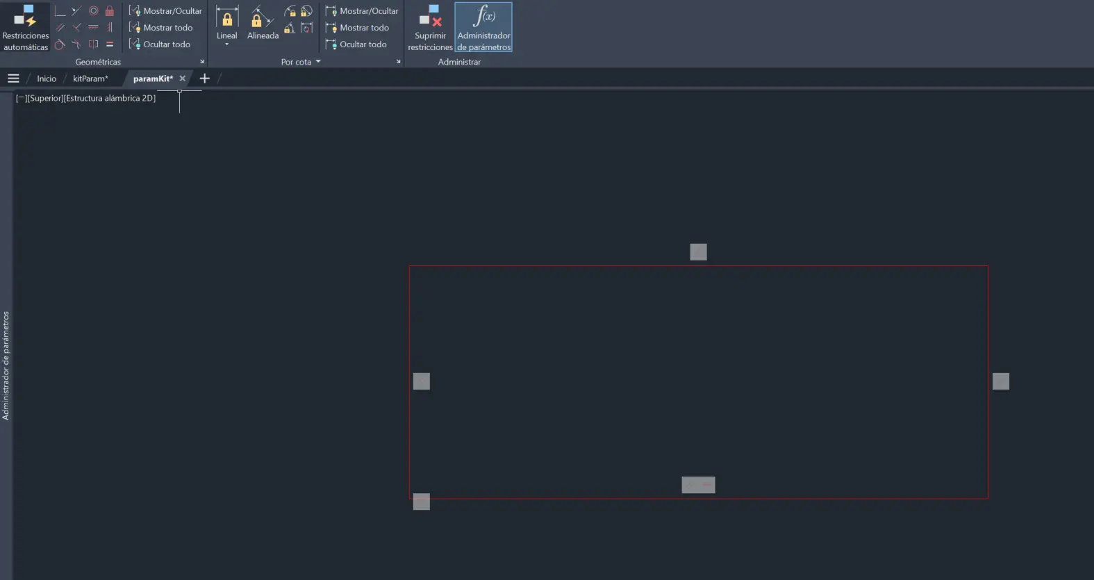
The little squares you see are the shape's parameters. If they bother you, you can always hide them with the "Hide all" button in the geometrical tab. Now, we can use a "Linear" tool to establish our shape's sides. To do this, select the "linear" tool, click on each corner of the side you are modifying and done! You can now enter your value as with the circle. You now know how to parameterize your most basic figures.
Mistake #2: I'm still not aware if this is the "best" way to make parametric designs in AutoCAD.
When Things Go Wrong
When learning a new skill, "failing" it's something that DOES NOT exists. You cannot "fail" at something you don't know. If you ever feel like you "failed" whilst learning a new skill, remember failure is the best teacher. You write your do and do not's, you stand up and keep moving forward with what you now know.
With all this said, it took me 3-4 versions to get to an "almost finished" state with my pieces, but not quite. 3 to 4 times where I decided the best course of action was to delete everything and start again.
I heavily underestimated the difficulty of AutoCAD parametric design. Like I've said before and will keep saying, I am no expert at any of this programs or skills. I'm learning on the go. But that's the spirit of the FAB Academy, learning on the go.
AutoCAD is probably one of the best (if not the best) CAD software for parametric design IF and only if you have the necesary skills under your bag. If not, it's a challenge doing things you feel should be easy.
I've been keeping track of the mistakes made during this section of my work. Here's the rest of the list:
Mistake #3: rotating pieces with gemotric restrains requires you to either enforce the restrains or loosen them. Enforcing them will prevent your model from moving correctly, and loosening will breake your parametric design.
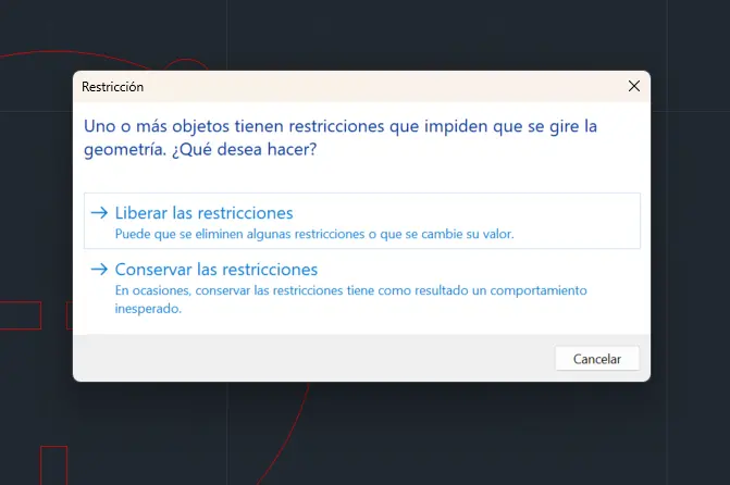
Translation: One or more objects have restrinctions that prohibits the geometry's rotation. What would you like to do? Free the restriccions or Conserve the restriccions
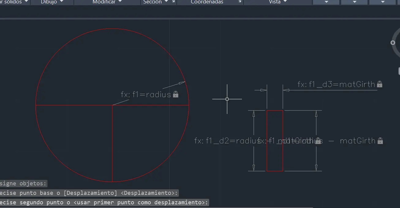
Mistake #4: I tried a method to scale the first 3 pieces in order to make a larger piece. This resulted in a new piece of the desired size, but with slots of bigger size
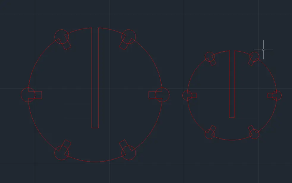
As you can see in the image, the sizes are ok, but the slot width should remain the same. I never figured an easy way to to this.
Mistake #5: When doing the re scaling of the slabs by hand, I totally forgot to parameterize it, completely ignoring the point of the exerciser.
Mistake #6: I made my situation worse by becoming desperate of AutoCAD's tools and trying to do it by hand with the most basic tools. This only lead to frustration and a desire to start over again and again.
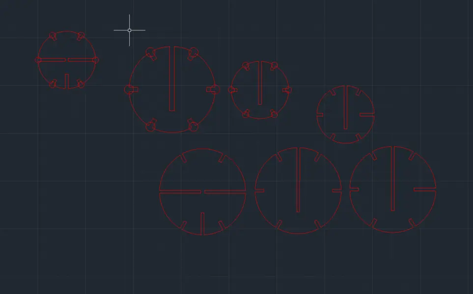
And so on… In the end I actually ended up with a "functional" set of pieces, intended for a "test" print. However, this pieces where not parametric, which defeats the purpose of the exerciser. The idea is to take this pieces and modify it's size with a simple changing of values. My pieces where not able to do that.
So, what do you do now?
If it Ain't Broke: OpenSCAD
After a long day of trying and trying with AutoCAD, I took a rest from it. Whilst resting, I remembered OpenSCAD can also make 2D designs and even exporting them in .dxf. So I tried doing my design in OpenSCAD. And let me tell you: at least for me, it was way easier.
Parametric Design Out the Box
For starters, OpenSCAD is parametric from the get go, as you only need to declare variables to use and change in you design. For me, my base parameters where as follows:
            $fn = 200;
            kerf = 0.136;
            matGirth    = 3 + kerf;
            indentDepth = 6 + kerf;
            indentNum   = 6;
            rotation    = 360 / indentNum;
            baseRadius = 20;

            pieceCount = 5;
The kerf is the value our class calculated from our Lab's laser cutters. "matGirth" refers to the material girth (3mm in this case). The rest of the variables are (excluding baseRadius) are supporting variables for our script based drawing.
The Base Piece
I started by modeling a base piece. Every other piece will be made of this base piece minus their corresponding indentations.
module basePiece(size) {

              radius = baseRadius * size;

              module indents() {
                  for (i = [0 : indentNum - 1]) {
                      rotate(rotation * i + 180)
                      translate([0, radius - indentDepth / 2, 0])
                      square([matGirth, indentDepth], true);
                  }
              }

              rotate(30)
              difference() {
                  circle(radius);
                  indents();
              }
          }
The code goes as follows. We first calculate our shape radius, using our baseRadius as starting point and multiplying it by the "size" or scale of the piece. We then create our indentations. With a for loop, we create, rotate and move our indentation rectangles. At last, we use a difference() to extract the indentations from the circle. And we are done!
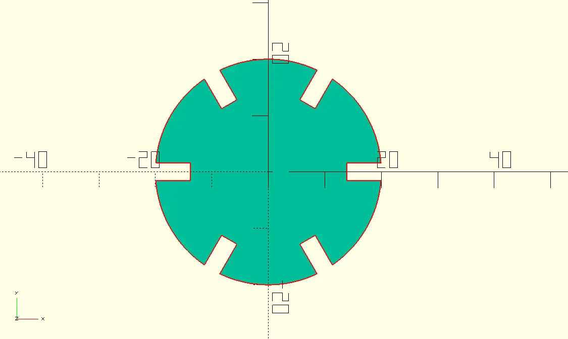
A few thing to point out before we move on: First of all, this felt way easier than using AutoCAD's tools (it's a personal opinion). Secondly, it took a little bit of time to get the positions right, but it was a "do it once" job, as every other base piece will stay the same. And at last, it is fully parametric, meaning that if the shape scales, what has to remain the same will remain the same.
I then created the 3 main pieces for the 3D sphere, by removing rectangles according to the schematics:
For this step, I created a module to select what type of rectangle size I needed to substract, as sizes remain consistant throughtout the schematic:
module joint(type, baseRadius) {

              if (type == 1) {
                  square([matGirth, baseRadius / 2], true);

              } else if (type == 2) {
                  square([matGirth, baseRadius - matGirth], true);

              } else if (type == 3) {
                  square([matGirth, (baseRadius * 2) - (baseRadius / 2)], true);

              } else {
                  echo("Error: Type number not allowed");
              }
          }
A simple if statement allowed me to create a shape at will. Here's an example of one of the figures I created with this module:
module fig1(size, radius) {
                  difference() {
                      basePiece(size);

                      translate([-(radius / 2), 0, 0])
                      rotate(90)
                      joint(2, radius);

                      translate([+(radius / 2), 0, 0])
                      rotate(-90)
                      joint(2, radius);

                      translate([0, -radius + radius / 4, 0])
                      joint(1, radius);
                  }
              }
It starts with a base piece. Then we create and move the corresponding piece, by adding a joint(type, radius) object. The type corresponded with the "medium" rectangle (1 for small, 2 for medium and 3 for large). It is important to note that both the joint and the figure will change with the scaling, but proportions will always remain the same.
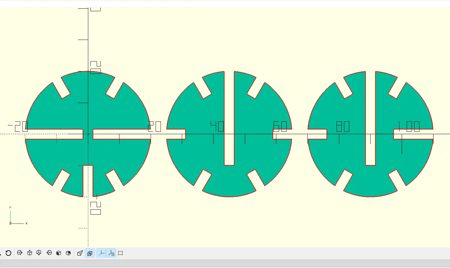
Finally, I created a for loop that created the neede pieces a set amount of times:
          for (i = [0 : pieceCount] ) {
              translate([baseRadius * 7 * i, 0, 0])
              figArray(1);
          }
          for (i = [0 : pieceCount - 1] ) {
              translate([baseRadius * 10 * i, baseRadius * 3, 0])
              figArray(1.5);
          }
          for (i = [0 : pieceCount - 2] ) {
              translate([baseRadius * 13 * i, baseRadius * 7, 0])
              figArray(2);
          }
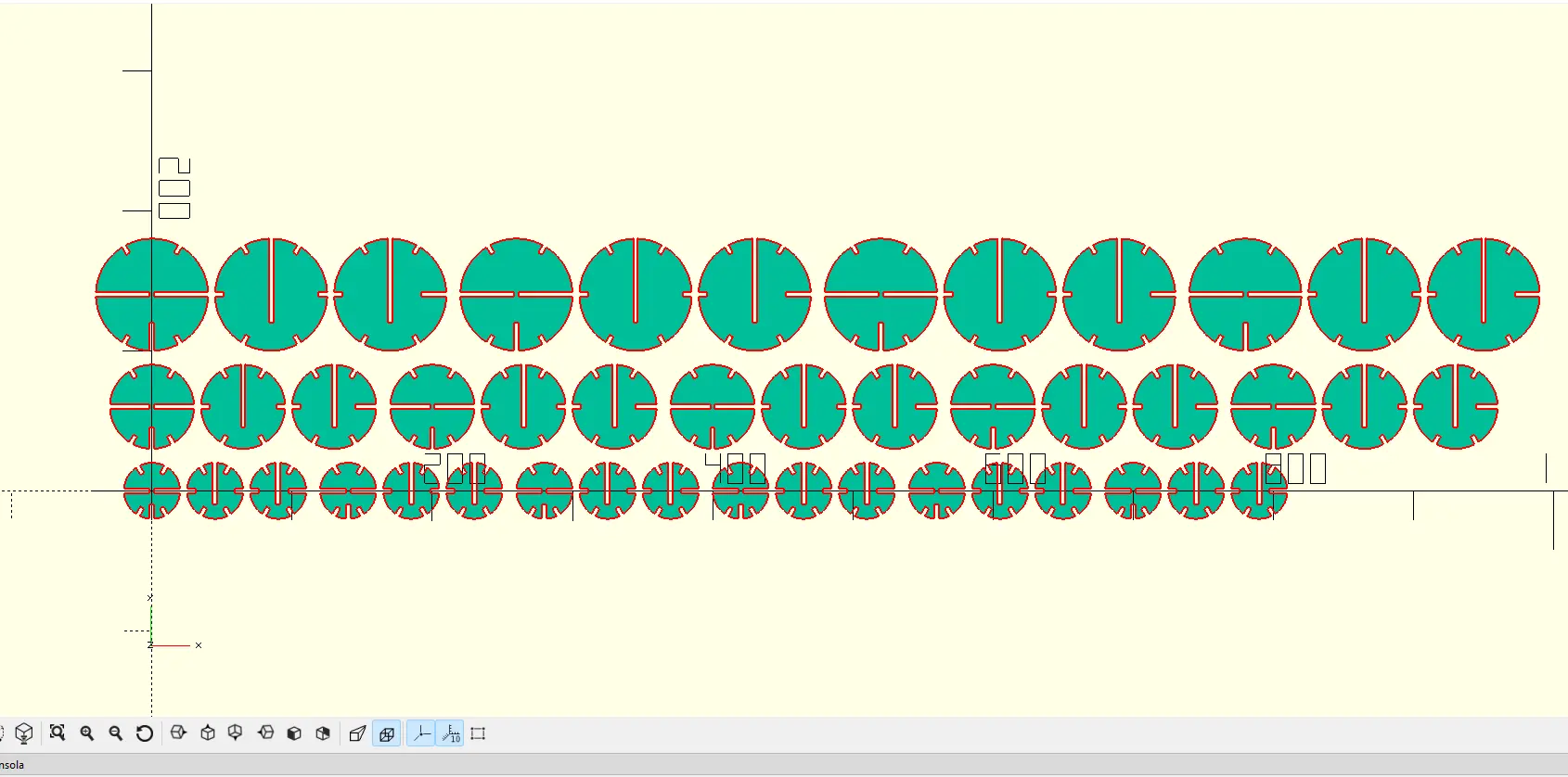
And ended up with this beauty:
Final Touches
I then exported this file as .dxf and imported it to AutoCAD. I did this in order to change the line's color to red (to the cutting layer), to rearrange the pieces to better fit in the MDF I planned on using, and joining all vertices to create a single line per object.
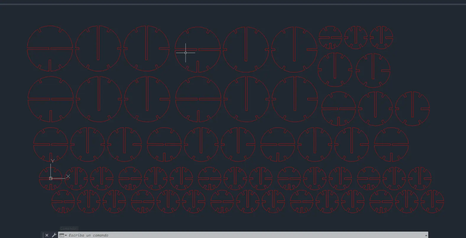
This step also allowed me to have a .dwg copy of the file.
The Bottom Line
I learnt a lot from this experience:
- There is no such thing as failing, it's just learning.
- "If it ain't broke, don't fix it". OpenSCAD proves again the power it has under the right hands.
- It is important to keep on learning these new Software, as they will eventually become an important part of my personal toolbox.
The Laser Cutter
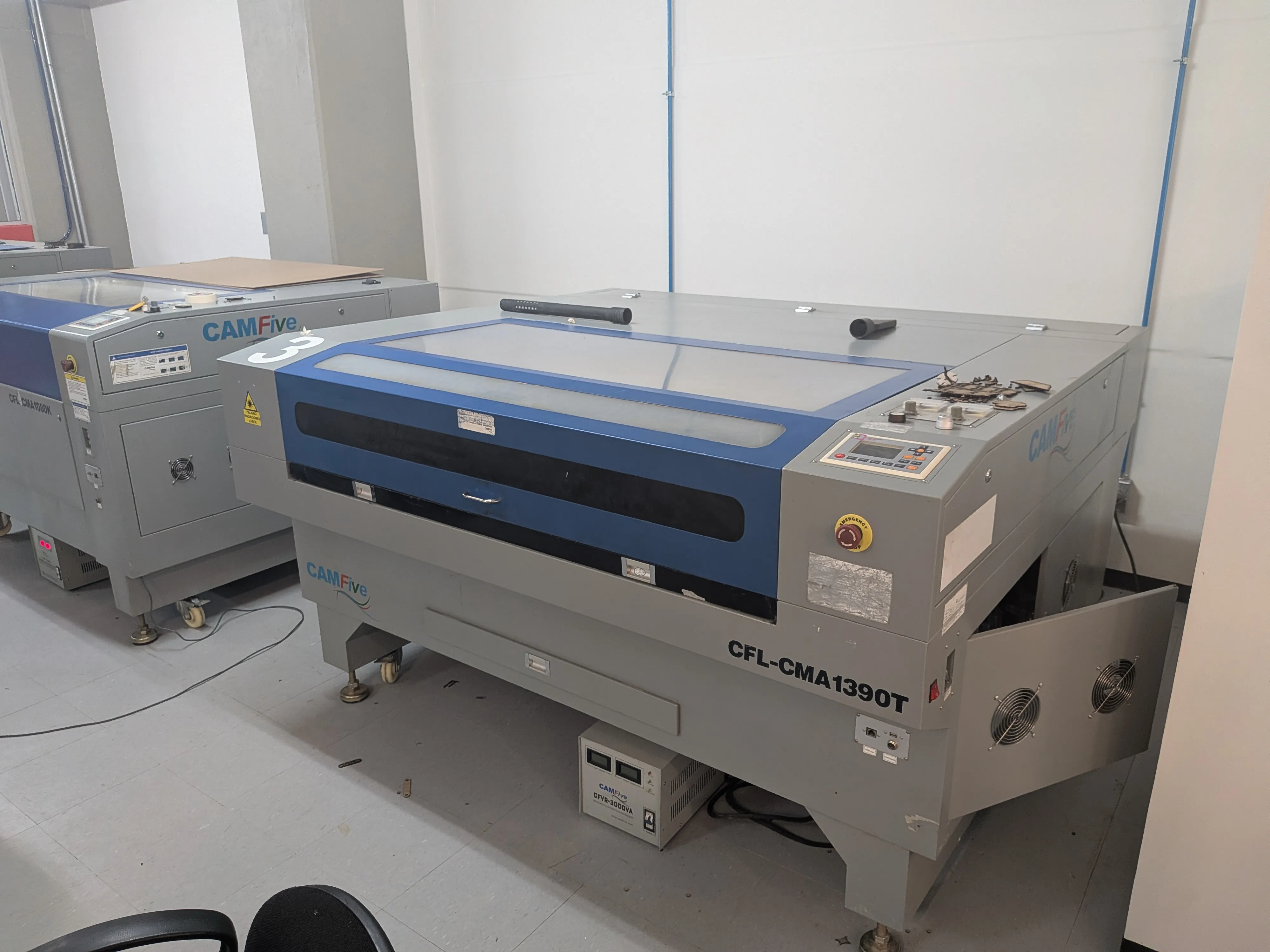
Now that we have our parametric kit file, it's time for using our Lab's laser cutter for the first time. Using the machine for the first time might feel intimidating at first, but it only requires you to follow a certain amount of steps to operate it, remember the laser cutter is meant to do all the work by itself after setting it up correctly.
Preparation Steps
Before using our laser cutter i we need to prepare ourselves. For starters, we need to take our Lab's safety and laser cutter usage course.
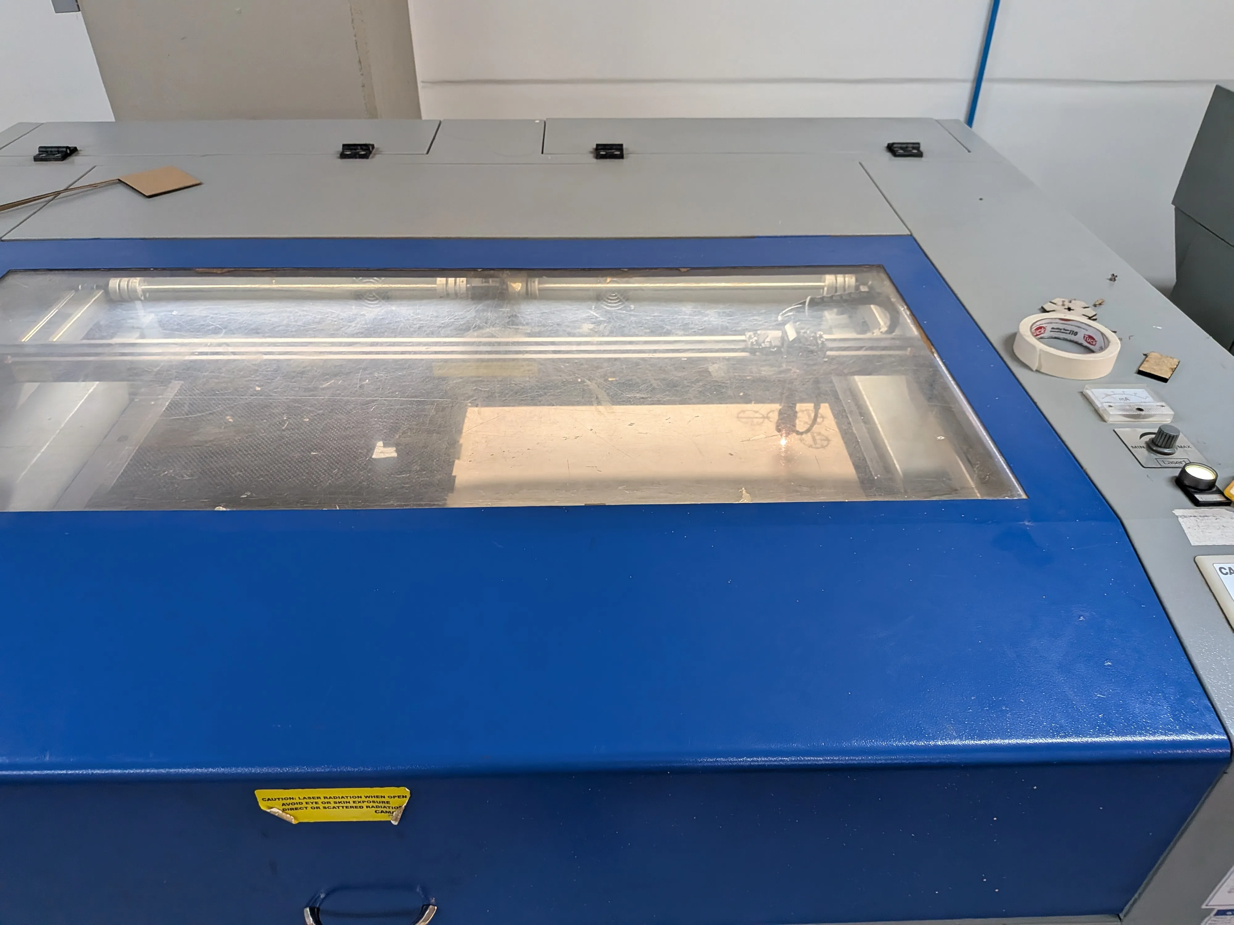
Preparing the Laser Cutter
Let's start making preparing our laser cutter! First of all we need to power it up. There are two main systems we need to start up: the auxiliary systems, like the exhaust system, and the laser itself, it that exact same order.
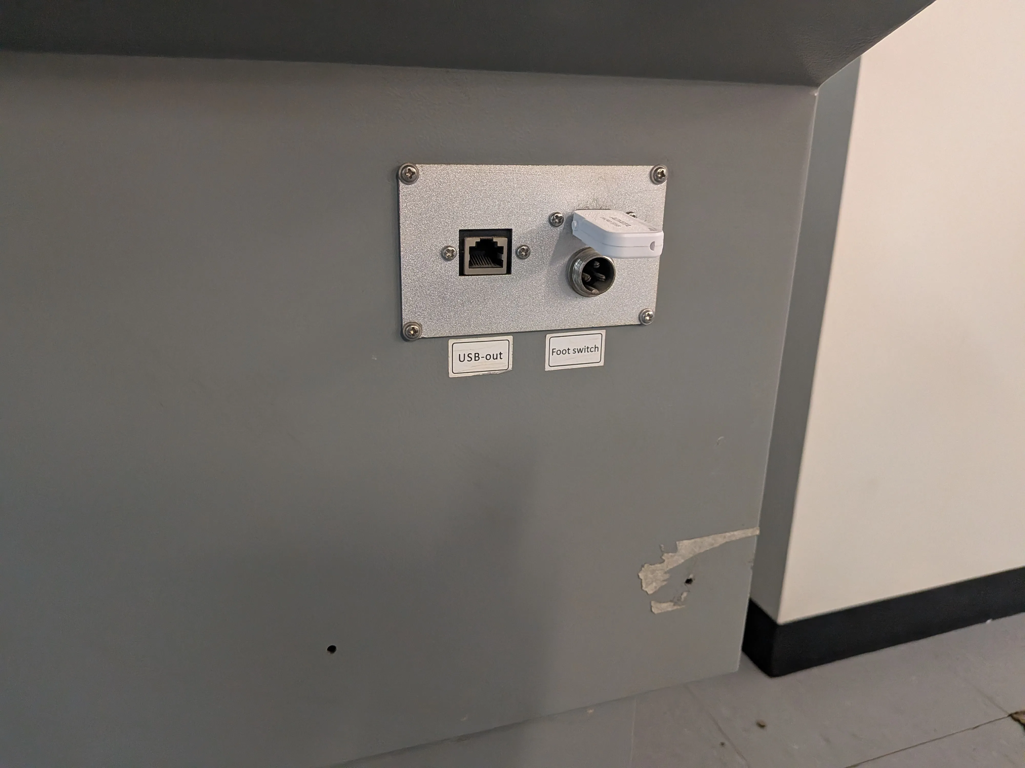
To do this, me must locate the auxiliary systems switch. In our Lab's cutter it's located on it's bottom. We can switch it on with our foot. We'll now it has correctly started up when the exhaust system starts making a lot of noise.
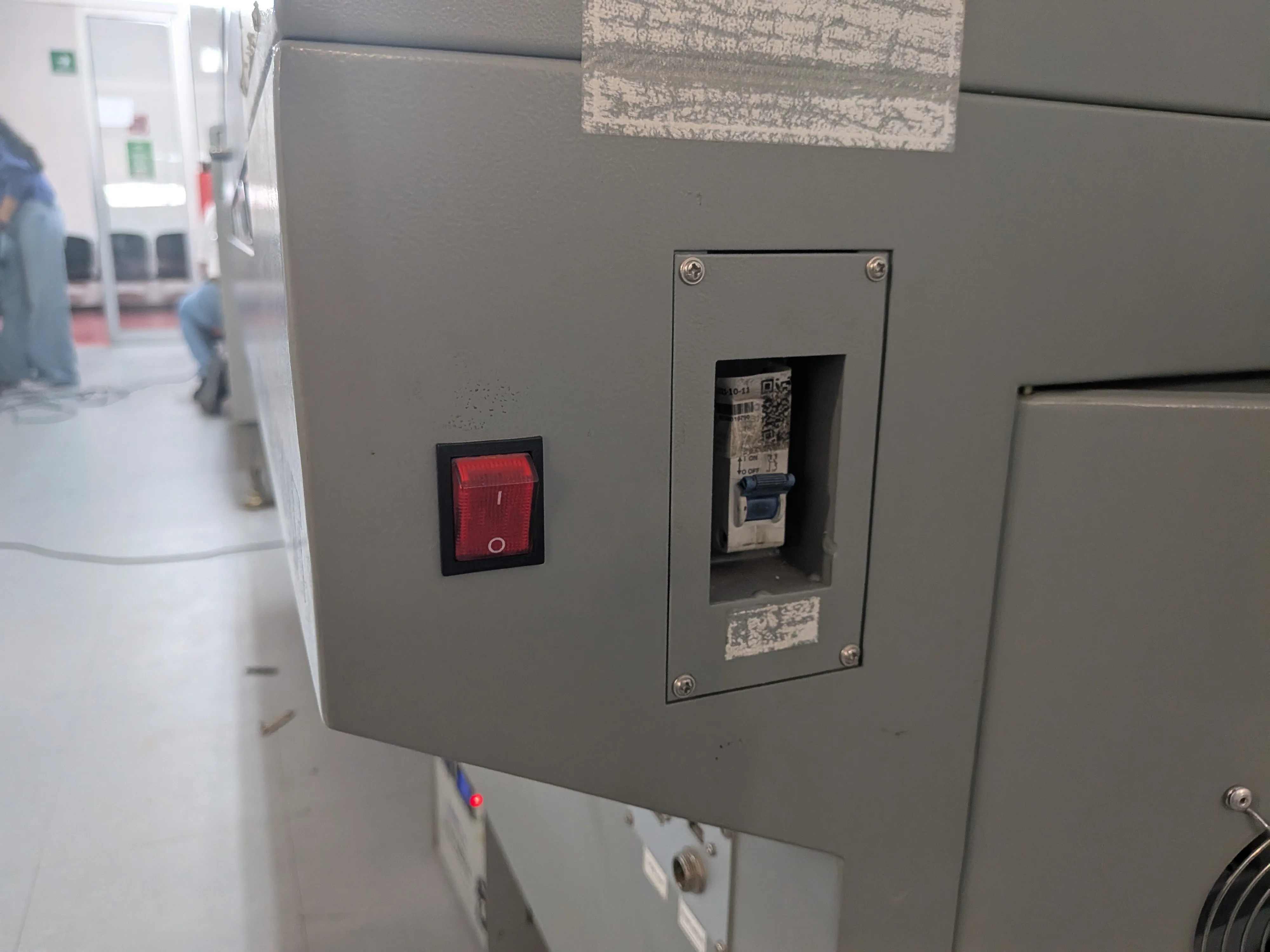
Now we can start the laser itself. To do this, we must first locate the laser's power switch on. It is usually located on the side of the cutter, if there is not maybe your cutter doesn't have this switch. Our Lab's cutter uses two switches, for example. Turn both on.
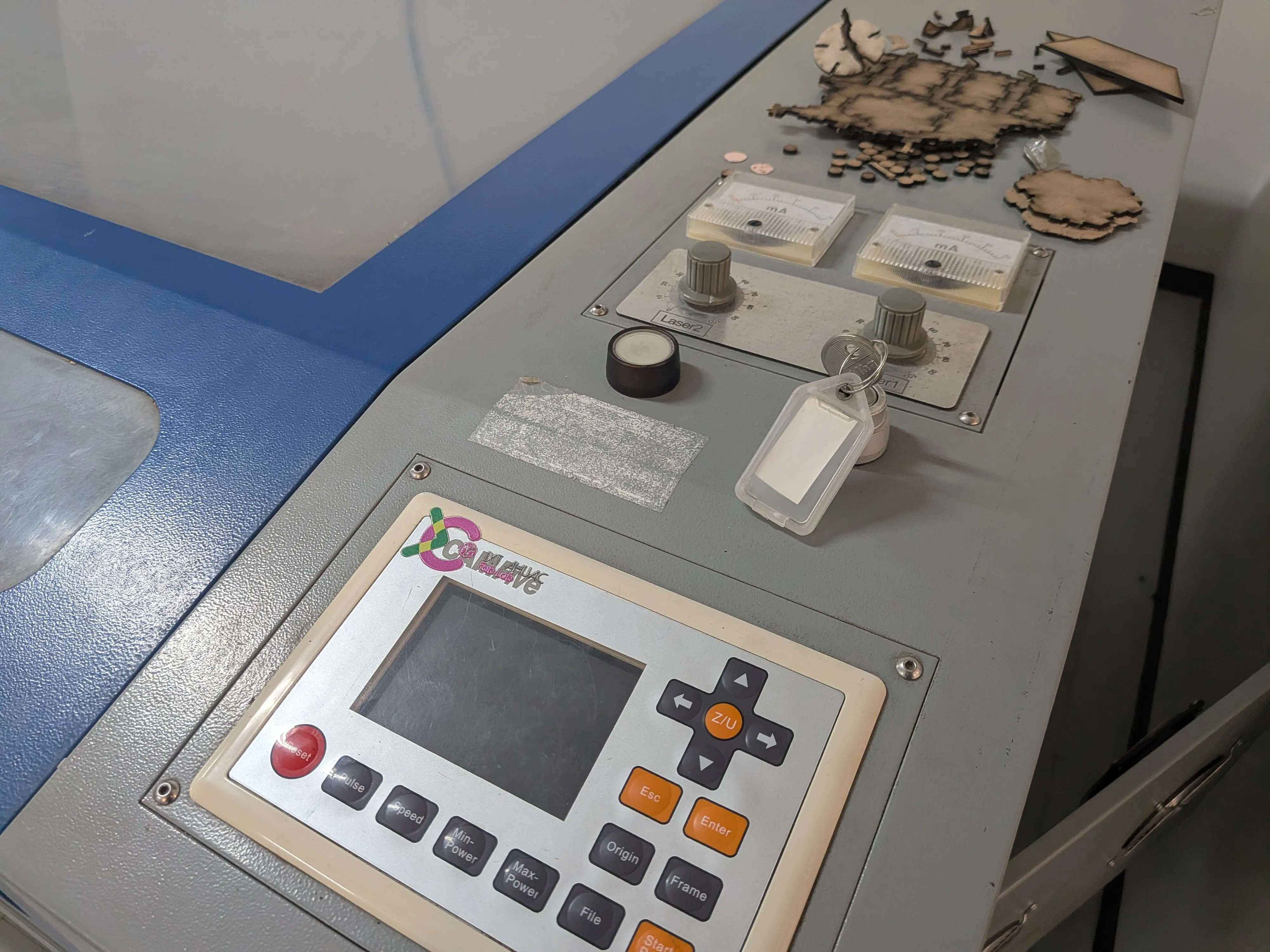
After this, we can finally power on our laser using it's safety key, given to us by the Lab's person in charge. We must enter the key inside it's keyhole and turn it right. The laser will power on. You will now this when the laser's screen turns on.
Preparing our File
Now we can now move on to prepare our file to send it. We have two options: Using a connected computer with the necessary program or the laser cutter itself. My personal preference is to use the computer, as you have a more visual control over our next configurations. If you prefer it, our your lab has no computer connected, you can connect a USB stick with your file in the corresponding USB port. Then, using the screen and buttons, import the file to your cutter.
For this case, we'll use the computer. First of all, we must open the cutters software. After that.
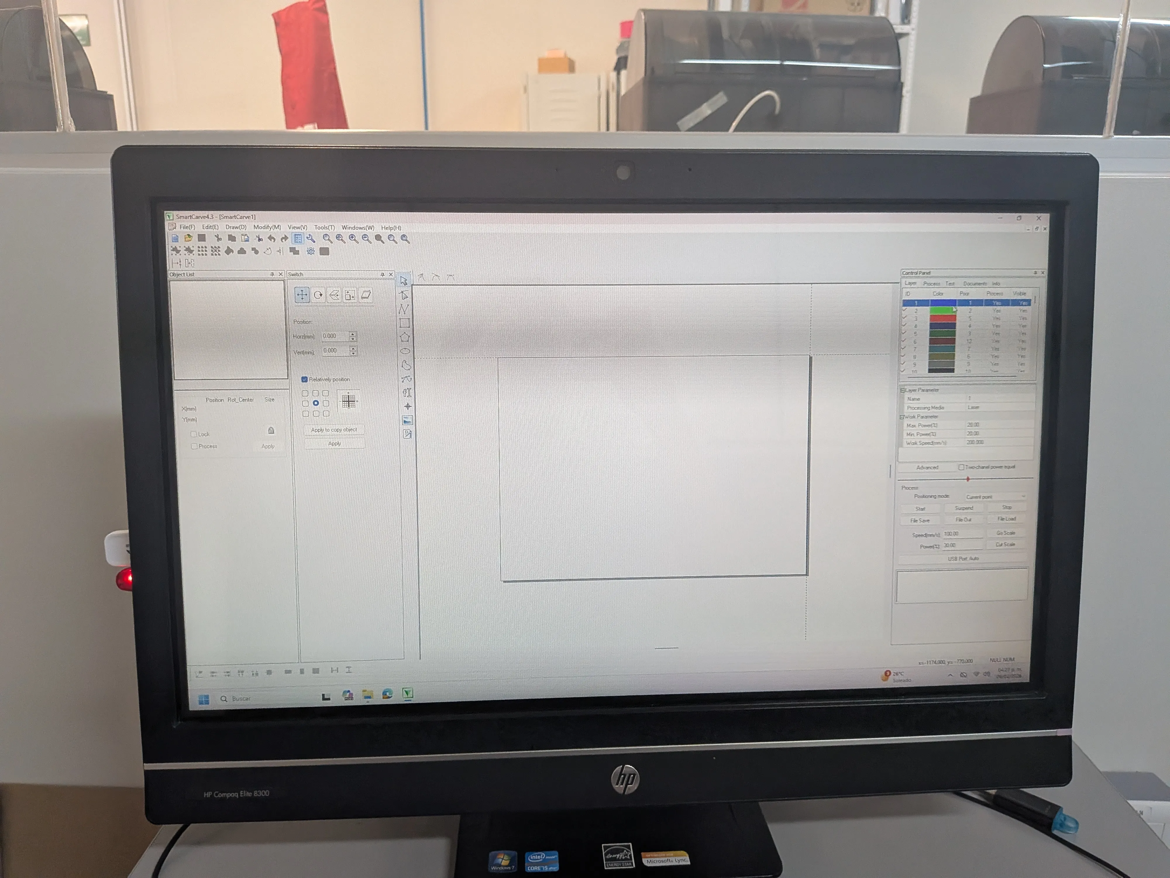
We then must import the .dxf file in the File > Import file menu. A window will appear asking you some parameters, just go with the defaults. Now you will see your design in your screen. You can now drag and drop your design to better fit the to-print area.
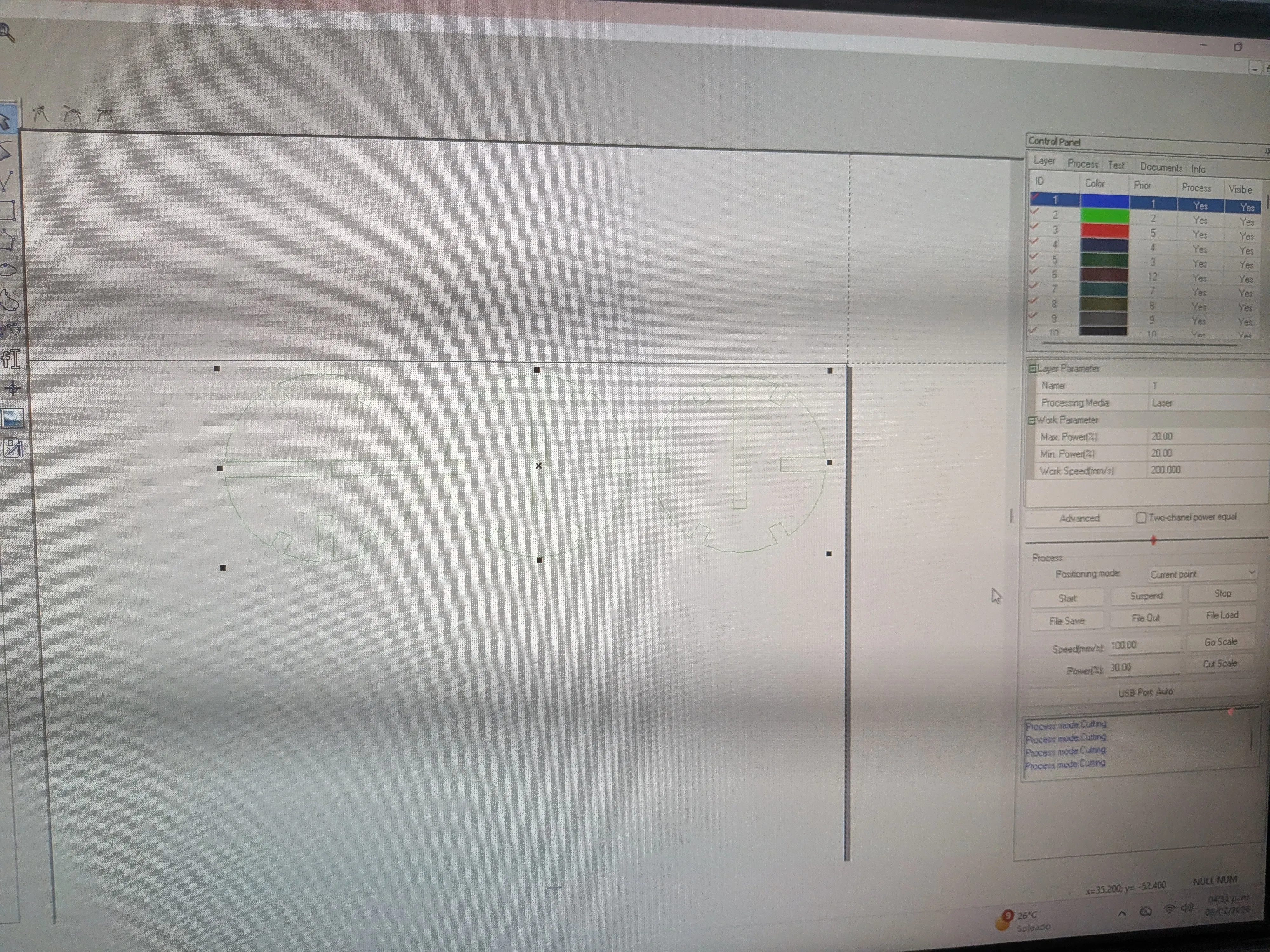
Leave some space between the borders and your design. In your left side of the screen, make sure that te 3x3 matrix has a check in the top right corner. If not, select it and then select apply. Your design might move to another zone. If so, move it back.
Now, we must configure our cutter's power and speed. this parameters will determine our cut's quality.
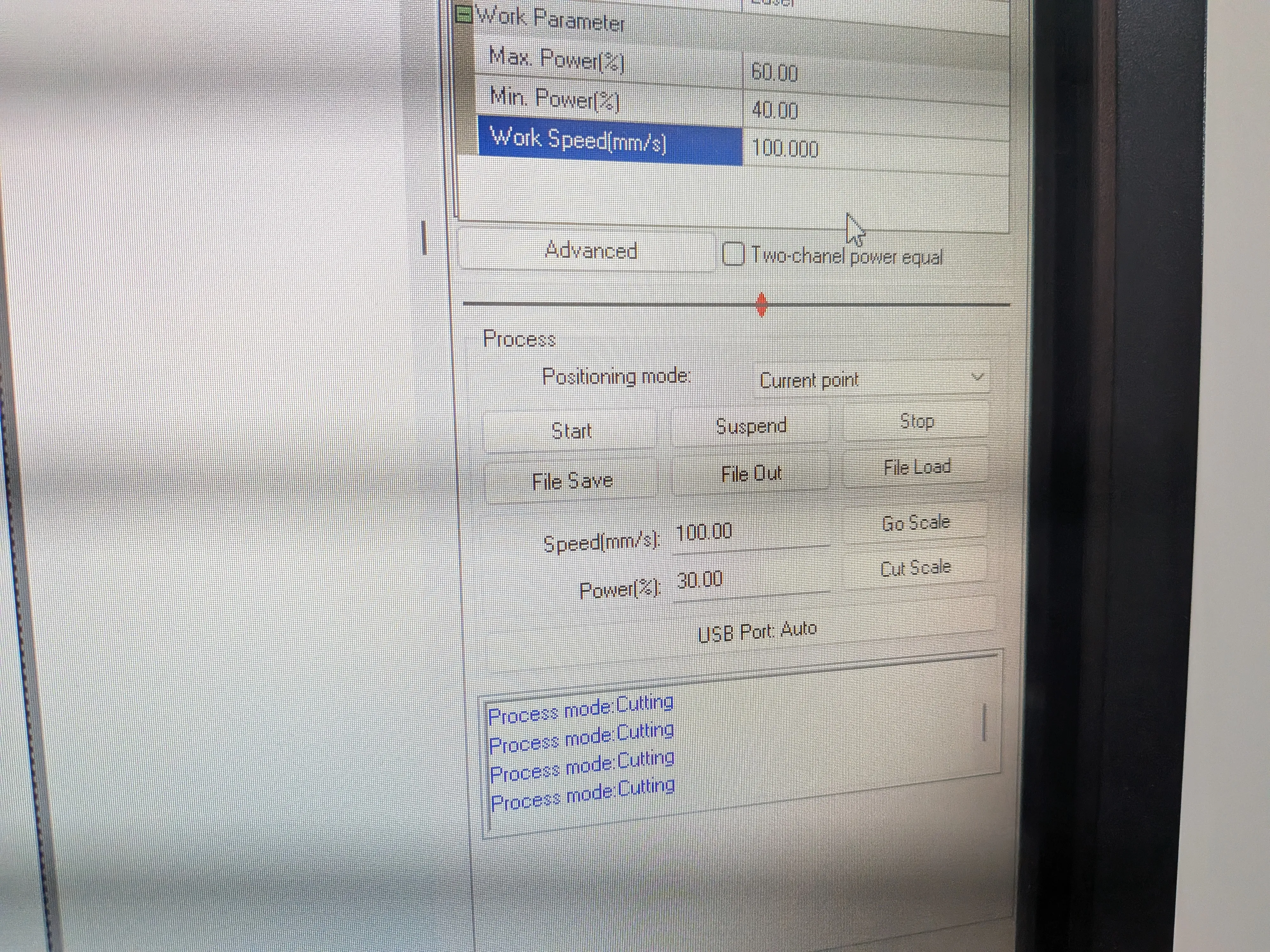
Power and Speed
The Max and Min power value determines the strength of your laser. The speed value determines the speed at which the laser will move. Setting this parameters correctly will make or break your design. A wrong configuration can make it so that your pieces are not completely cut (called engraving). It can also burn your final product.
There is no exact values to use for a material, so the best way is to manually test it. We'll get to that later. For now you must know for my case, I used a Max power of 80, Min power of 75, and speed of 25. It's important to note though, this values burned my material a bit.
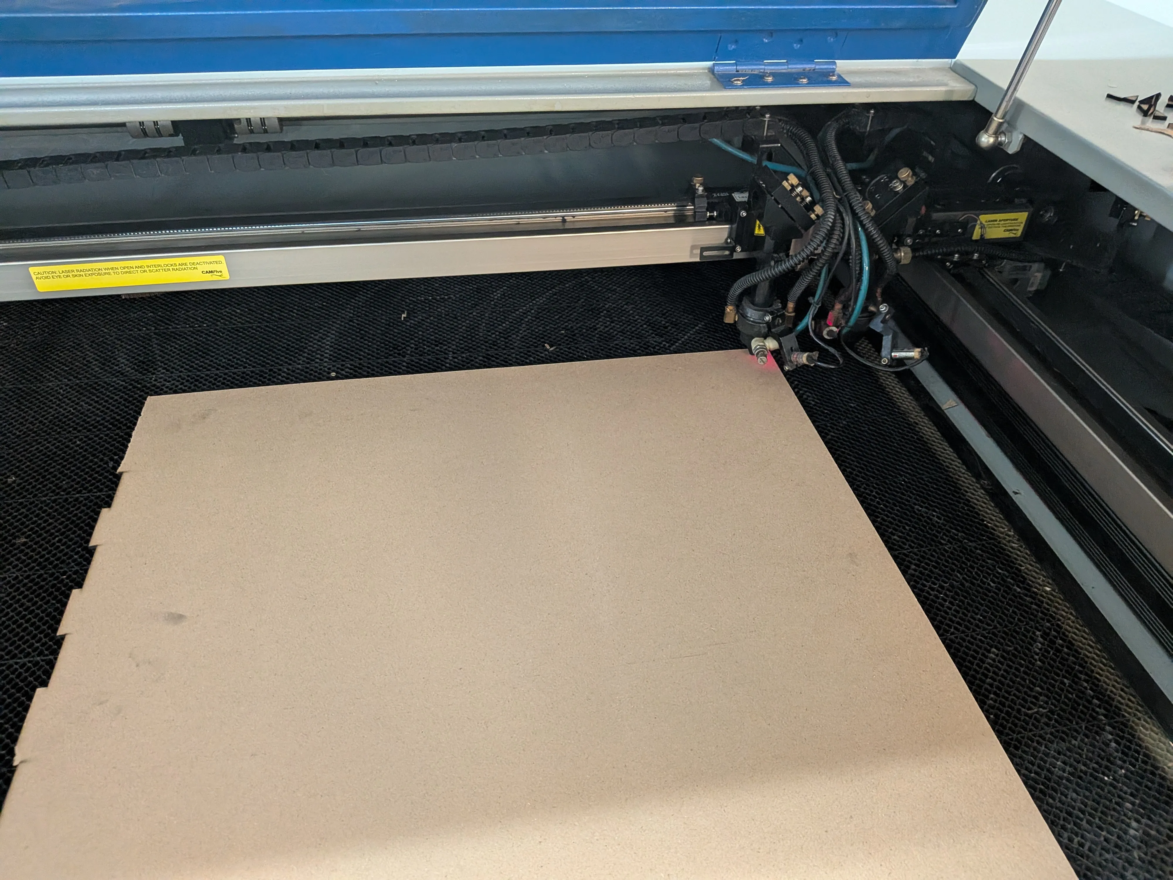
Laser Cutting our File
With our file ready and our parameters set, its time to set our material inside the laser. Before that we need to take some precautions. In the cutter's control panel, there is a button with a "laser" label. When this button is lit, the laser is lit. DO NOT open the laser cutter's lid, as the laser is active and can harm you. Turn off the button and open the lid. When the lid is open you can now place your material in the bay.
Now, with the arrow set in the control panel, change the placement of your laser to meet your desired starting spot. After the laser is in place, click the "Origin" button.
Now, close the lid. You can now press the "Laser" button, and make sure the power knob is set to max. From now on YOU MUST NOT open the lid.
Starting the Cut
Go back to your computer software and press "start".
The laser will now start cutting! Make sure to not look directly for prolonged periods of time, as it may hurt your eyes. Also, be present during every moment of the cut, as if something where to go wrong you must be ready to act. In case of something going wrong, there is an emergency stop button on the side of the cutter.
After the Cutting
After the machine is done cutting, a sound will be made. You must wait a bit before opening the lid again. The extraction system will purge the bay of any toxic gases that might have been released during the cut (the classic "Laser cutting smell"). And before opening the lid, turn off the Laser with the "Laser" button.
With all this done, you can open the lid and retrieve your laser cut pieces.
Turning off the Laser Cutter
After you are done with the laser cutter, we must turn it off. To do this, close the lid and turn off the laser. A good practice is to turn the power knob to Min. Now, remove your ignition key and turn off all the main laser power switches. And at last, you can turn off the auxiliary systems switch on the bottom. Make sure to also clean every scrap you left, be considerate!
And with that, we are done using the laser cutter!
The Final Result
Before going into the final result is important to note everything that happened during my use of the Laser Cutter.
First of all, the kerf. Understanding the kerf was a bit trickier than I expected. During our laser course, we calculated our laser's kerf to be around 0.36mm. I accounted this kerf into my design, but instead of adding it when I needed to, I accidentally removed it. So when my first test pieces came out of the cutter, the pieces connections wouldn't fit.
It took me 9 test runs to finally get an acceptable slab and tab connection that wasn't too loose or too tight. Testing is important, but it will always depend on your available time with the laser. With practice comes experience, and the more projects you do with the laser cutter the time required to get your pieces right.
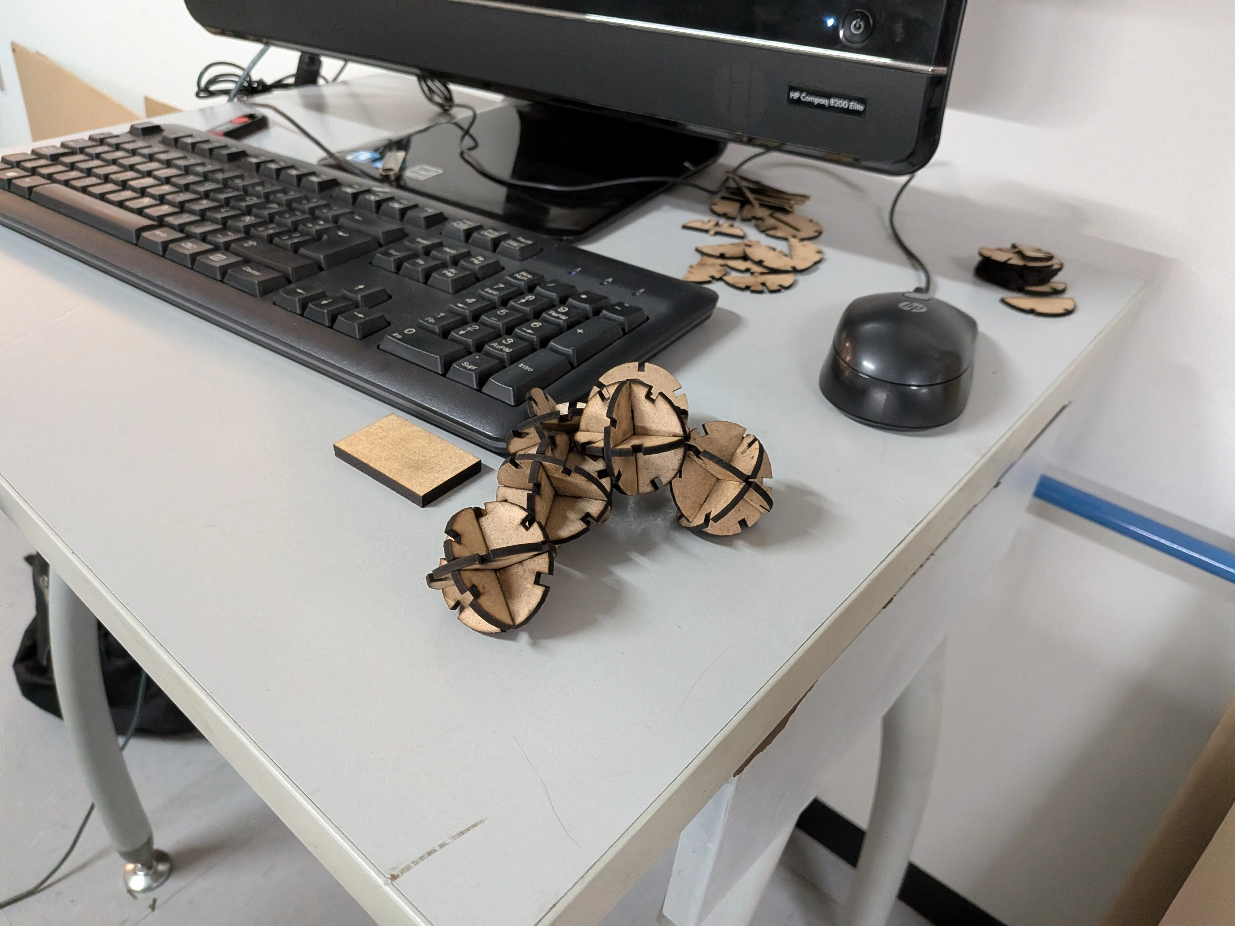
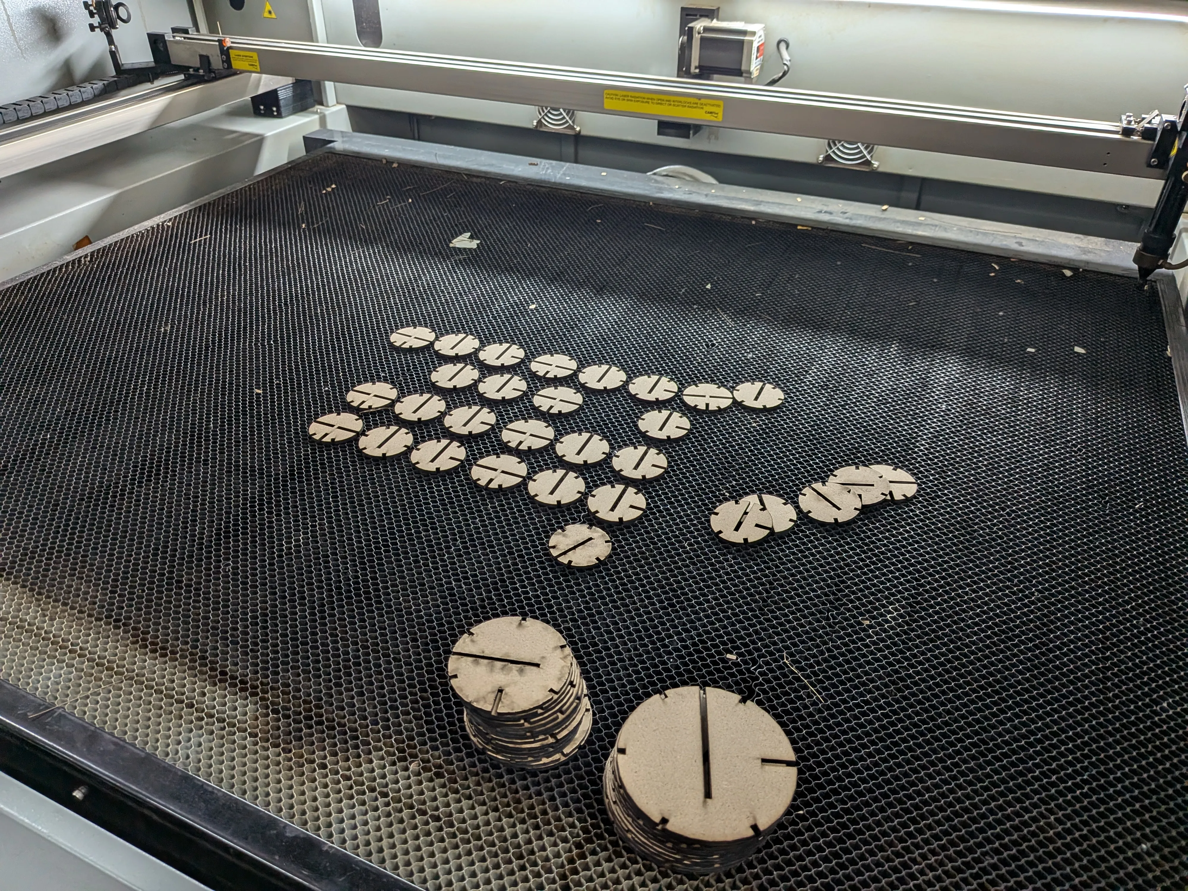
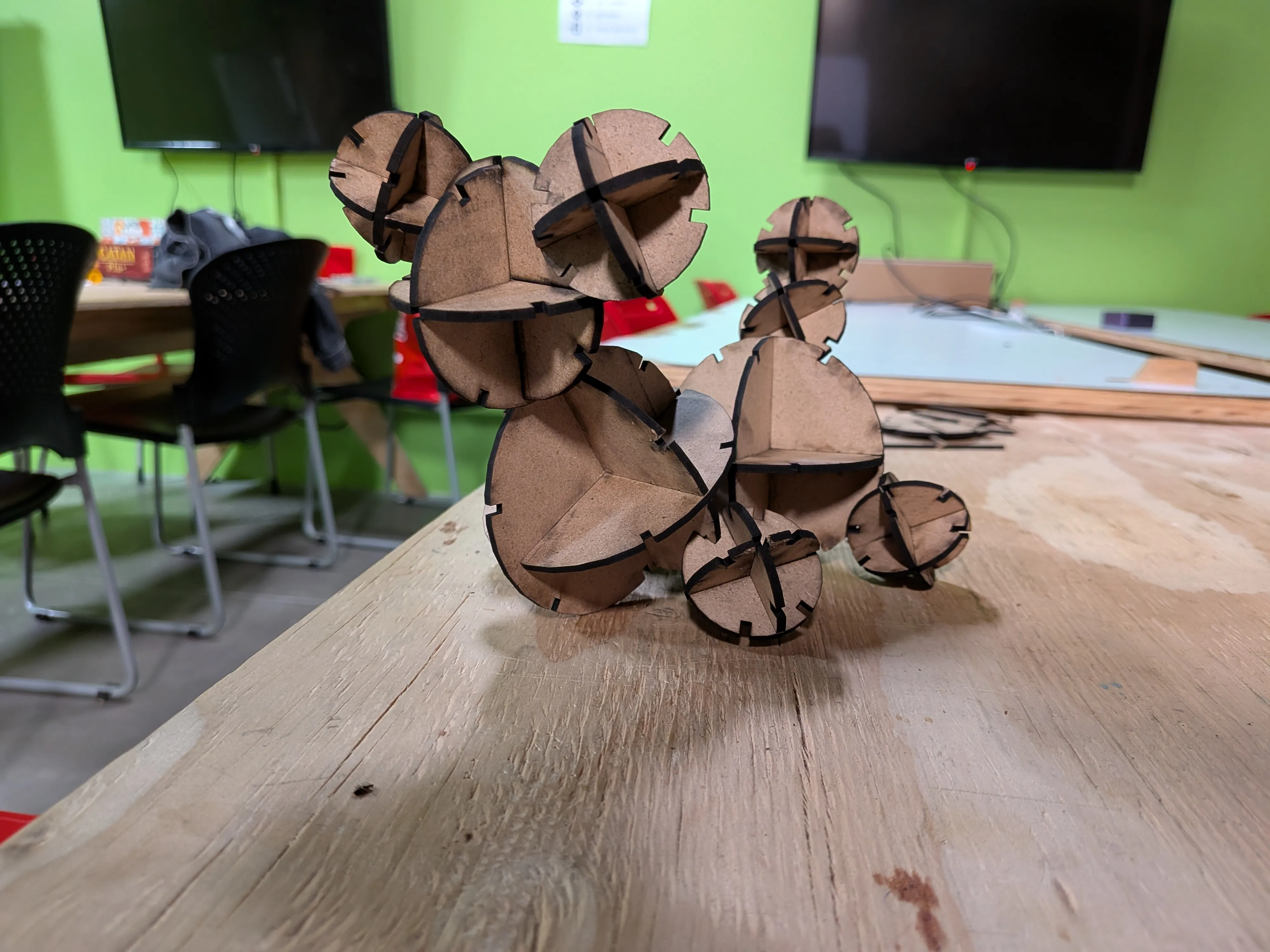
In the end, I got a fully parametric kit of 3D spheres of three different sizes. I made a little demonstration of what my pieces can do:
Vinyl Cutting
Vinyl cutting refers to the process of creating a design and producing it in vinyl, a self adhesive colored material most commonly used for stamping into materials. It might not seem like it at first, but vinyl cutting is really useful skill to learn, specially when planning for detailing and stylizing our projects. Vinyl can take the form of text, shapes, indications, decorations, etc. Mastering the vinyl cutter is easy and will open up doors for you and your future projects.
Getting Started
In order to produce a design in Vinyl, we need a design in the first case. We can use any CAD software, like we learned to last week, that can export SVG files (more on that later). AutoCAD, for example, has the option of exporting designs as SVG. The problem with AutoCAD is that is is designed for more “precision focused” designs. Vinyl cutting lends itself for more creative and free designs. For that case, a program like Adobe Illustrator might be a better choice. However, Illustrator is a paid software. If you have access to Illustrator, that’s great. For the rest of us, there is one amazing open-source alternative: Inkscape
Inkscape
Inkscape is a CAD software mostly used for design projects (think about it like a professional Canva). Inkscape is great for our vinyl designing, as it includes a vast variety of tools that can help us to create said designs. To use Inkscape, you can install it from its official Download page. Once installed, open it up.
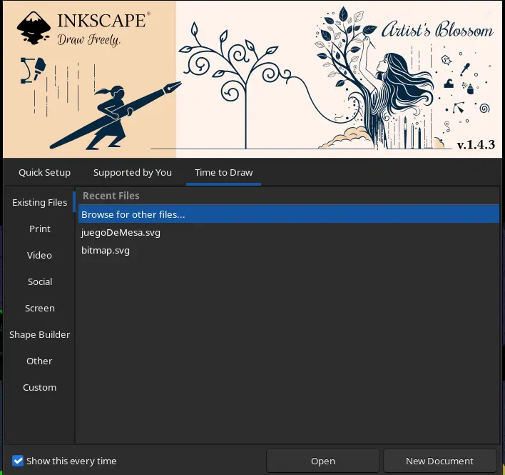
Now, click “New Document”.
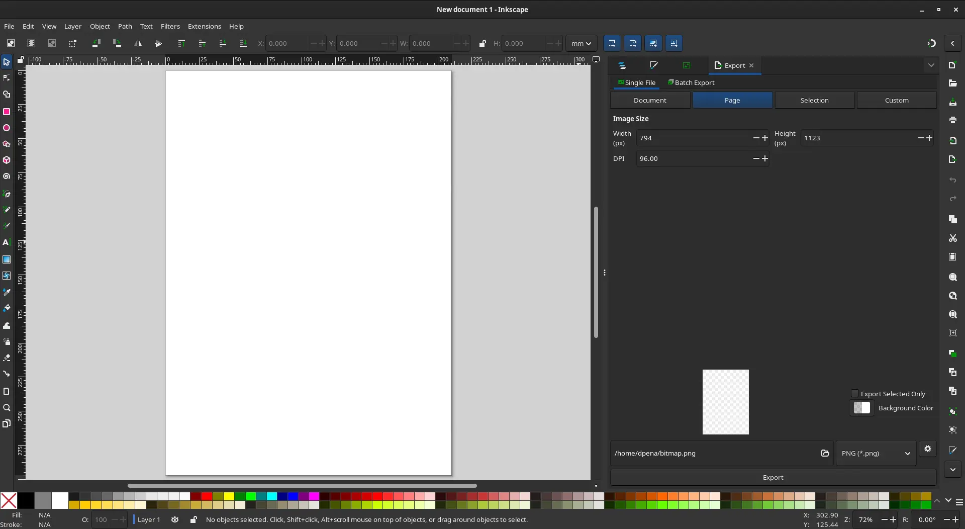
This will be your workspace. It might seem intimidating at first, even more if it is your first time using this kind of CAD software. I recommend watching a quick YouTube video to get to now the Inkscape interface and all your available tools, like this video from the Skill Factory channel.
Choosing our design
We can perfectly create of own designs from here. But for simplicity sake, we will be using an already made design. This design needs to be:
- Small.
- Simple
- Black and white.
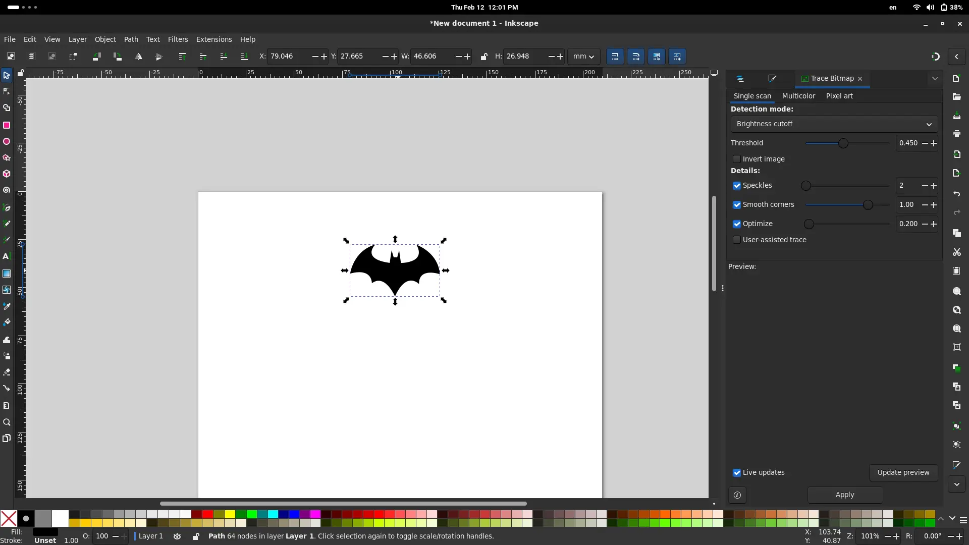
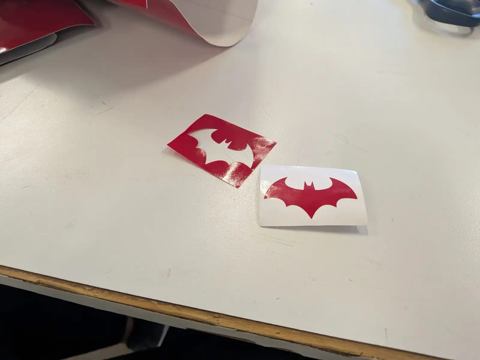
I decided to do the Batman logo, not for a particular reason. The Batman logo is perfect, as it is composed from simple lines, can be scaled to be small, and can be easily found in black and white.

Now that we have our image, we can import it into Inkscape by just dragging and dropping it into your work area.
Setting up the Page
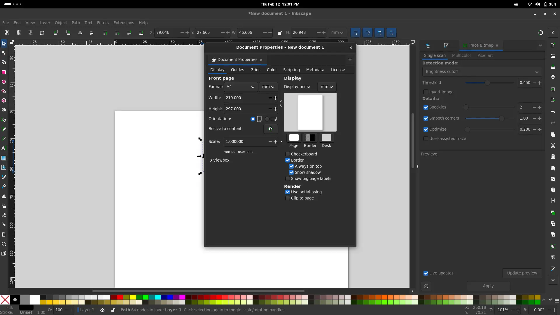
To make sure our design will be the size we want it to be, we can adjust our page size in order to work in an area identical to our available space. To do this, simply navigate to File > Document Properties. A window will appear. Change the width and height of your page to your desired size. You can also change your units from mm to inches. KEEP IN MIND, your design will need a little bit of padding on each side to be properly cut in the vinyl machine. So make your page a little bit bigger that what you actually need it to be.
Now, our page is the size we want it to be. If your design is bigger that the page, scale it down using the arrows on the corners of your png. If the arrows are not pointing outside the image, but in a curve, it means you are in rotation mode. You can change to scaling mode by just clicking the image once. Also, if you wish to keep the original proportions of your image, click SHIFT while you drag your image to re scale it maintaining its proportions.
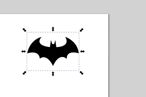
Now, our image should be the size of your page, with the additional padding to each side I mentioned before.
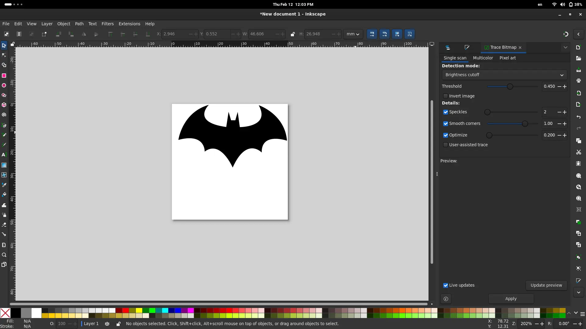
Tracing the Image
We are now using a png image. We need to convert it into an SVG object. SVG, or Scalable Vector Graphics, is a type of image that can can be scaled and will always maintain its quality. SVG images are a series of coordinates from which lines are traced. This coordinates maintain a mathematical relationship to one another, which means that scaling it to a factor of 5% means that each point on the coordinate will be scaled by 5%.
Our vinyl cutting machine needs an SVG file, as it will be tracing the paths created by those coordinates I talked about. Luckily for us, we can easily convert this png images into SVG. This is why we needed a black and white picture.
To do this, navigate to Path > Trace Bitmap. A menu will appear on your right side bar. Select you png and click “Apply”. Your SVG image will be created on top of you existing image. Move it to the side and erase the original image. If at any point you are unaware of which image is which, you can verify it by navigating to Layer > Layers and Objects. A menu will appear. The SVG image will appear as a “path”. Alternatively, clicking the SVG image will show may squares and circles on its border.
Exporting the SVG File
Now that our design is ready, we can simply export it as an SVG file. To do this, navigate to File > Export as. A menu will appear. Select “Plain SVG” on the drop-down menu above the “Export” button and hit “Export”
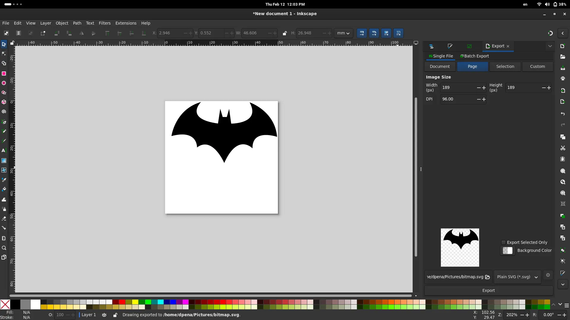
We are now ready for the Vinyl cutter!
(Using) The Vinyl Cutter
“Using” the vinyl cutter comes with a catch. We won’t be really operating the machine itself. Our vinyl cutter directly from Inkscape is possible, but requires a plug in and some configurations in order to work properly. Thankfully, one of our local instructors has already made every configuration needed to operate the machine. The problem? it is all in her computer.
This doesn’t mean that our work is over here. We might not be able to send our file directly to the machine, but we can (and must) set it up.
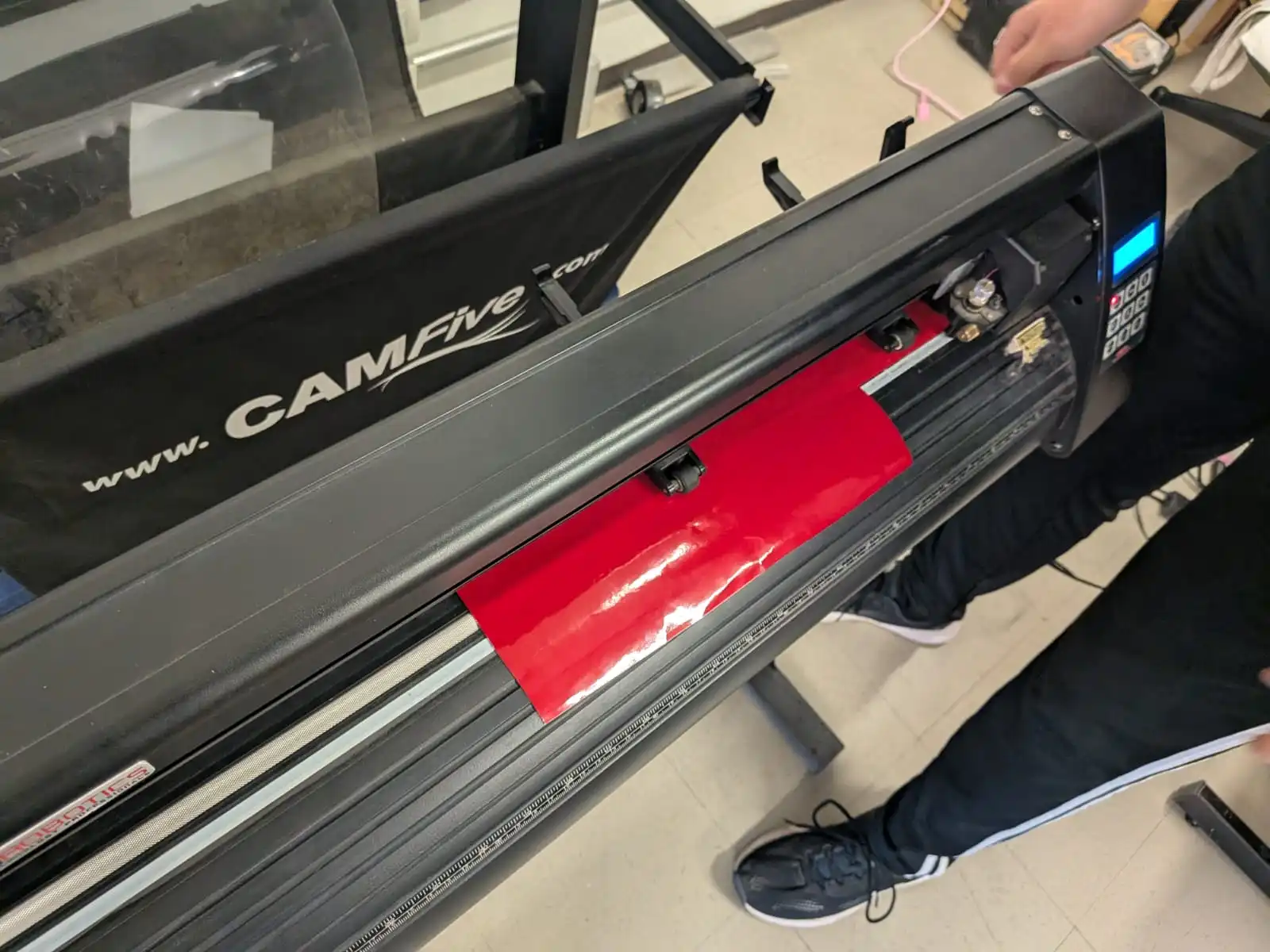
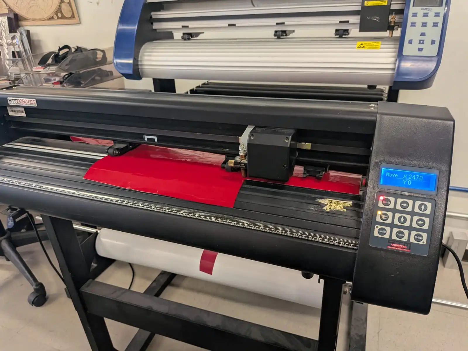
Setting up the machine requires us to place the vinyl in place. To do this, the machine has a series of “clips” we need to loosen up. These clips are sometimes hard, so you will need to apply some force to them, be careful! When the clips are up, place the vinyl from the back side of the machine.
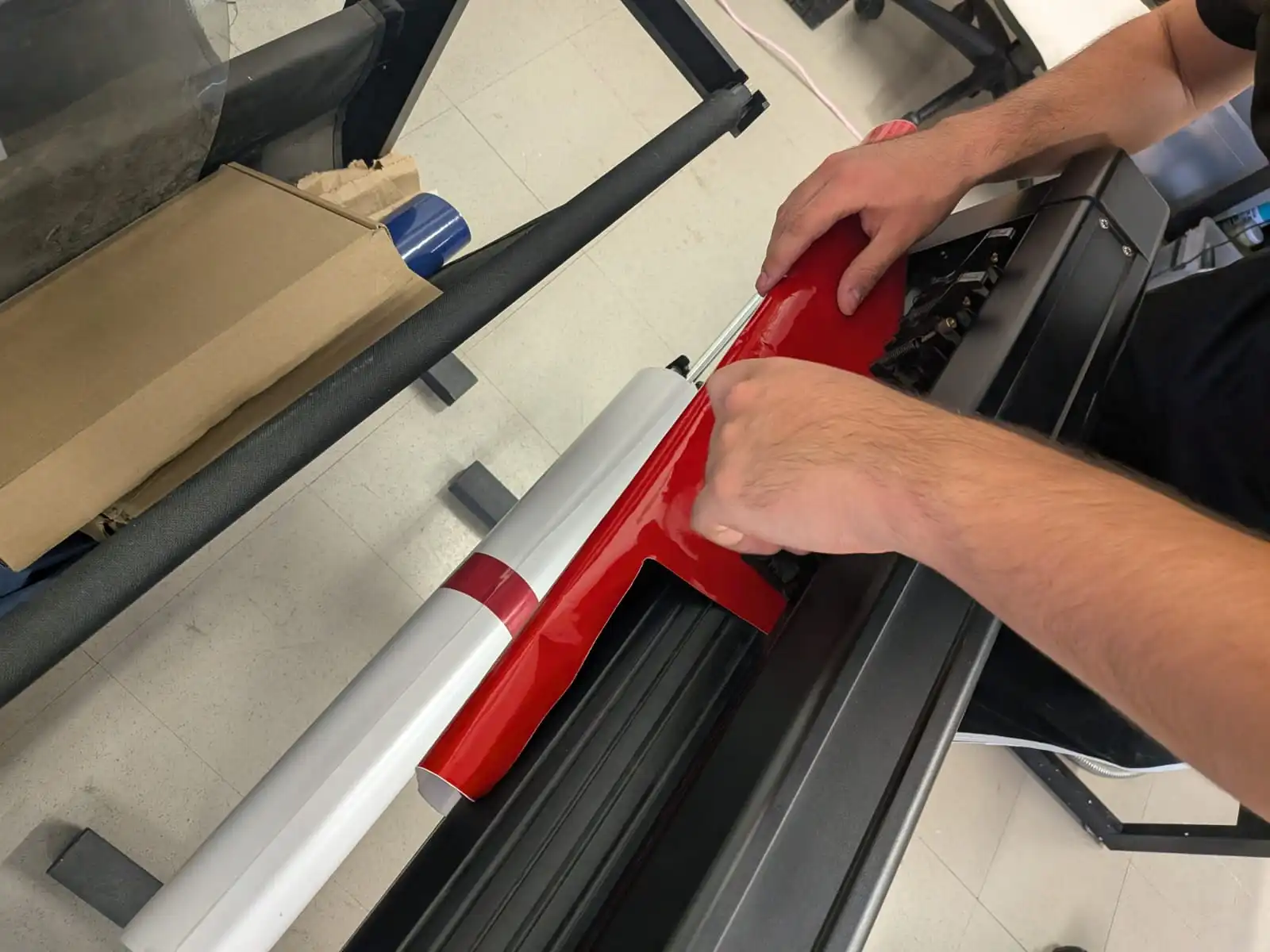
The area of the vinyl we will be using needs to come a out of the machine. For our small design it looks like an overhang, but in reality is the area of our cut. When our vinyl is properly placed, push the clips back down to secure it.
Now, we are ready to lend our file to our instructor and cut our vinyl!
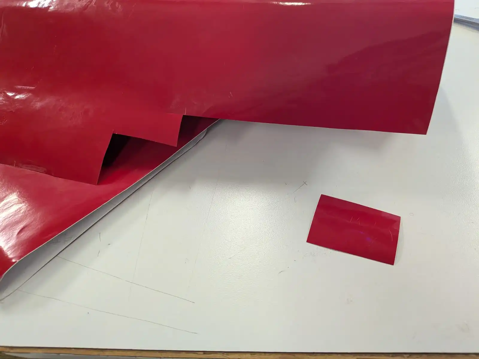
Once the cut is ready, we will be left with the design carved into the whole vinyl. We can retrieve our design by cutting it out from the vinyl, in a rectangular shape that contains it.
Our design is not ready to place yet, as we need to transfer it to a transfer paper. To do this, remove the protective layer underneath our vinyl rectangle and paste the vinyl into the transfer paper. Now we need to make sure our design is correctly placed in our transfer paper. You can use a credit card to press transfer papar to the vinyl from underneath. At last, remove the excess vinyl from the transfer paper. Now Your design is ready to be pasted where you desire!
In order to paste you design, lift up a part of the vinyl (starting from its left and right sides), fold the transfer paper underneath it and paste it on your desired spot. Now, slowly remove the transfer paper from underneath whilst pasting the vinyl. And you are done! Your vinyl design is now placed.