Microcontrollers
ESP32 and ATmega328P.
Fab Academy 2026
Exploring microcontrollers, datasheets, PWM, ADC and embedded programming using the ATmega328P and ESP32.
ESP32 and ATmega328P.
PWM, ADC, timers, interrupts and embedded systems.
A programmable electronic piano using PWM sound generation.
This week, during the group assignment, I reinforced something important: the architecture of a microcontroller really affects performance, power consumption and even the way you approach development.
It’s not only about choosing a board that works. The internal structure shapes how the entire system behaves.
I also understood that the datasheet is not optional. It is the real manual of the device, and if you want to truly understand what you are doing, you have to read it carefully.
Another important lesson was about programming languages. Choosing a language is similar to choosing a microcontroller: there is no universal “best” option. The correct choice depends on the project requirements and development goals.
Group Assignment – Embedded ProgrammingFor my final project, I evaluated several microcontrollers to determine which one best suited my needs.
I analyzed specifications, power consumption and available features before deciding to use the ESP32 because of its integrated Wi-Fi and Bluetooth capabilities.
ESP32 Datasheet3.0V – 3.6V with 3.3V logic levels.
Built-in Wi-Fi and Bluetooth Low Energy support.
Deep sleep current in the microamp range.
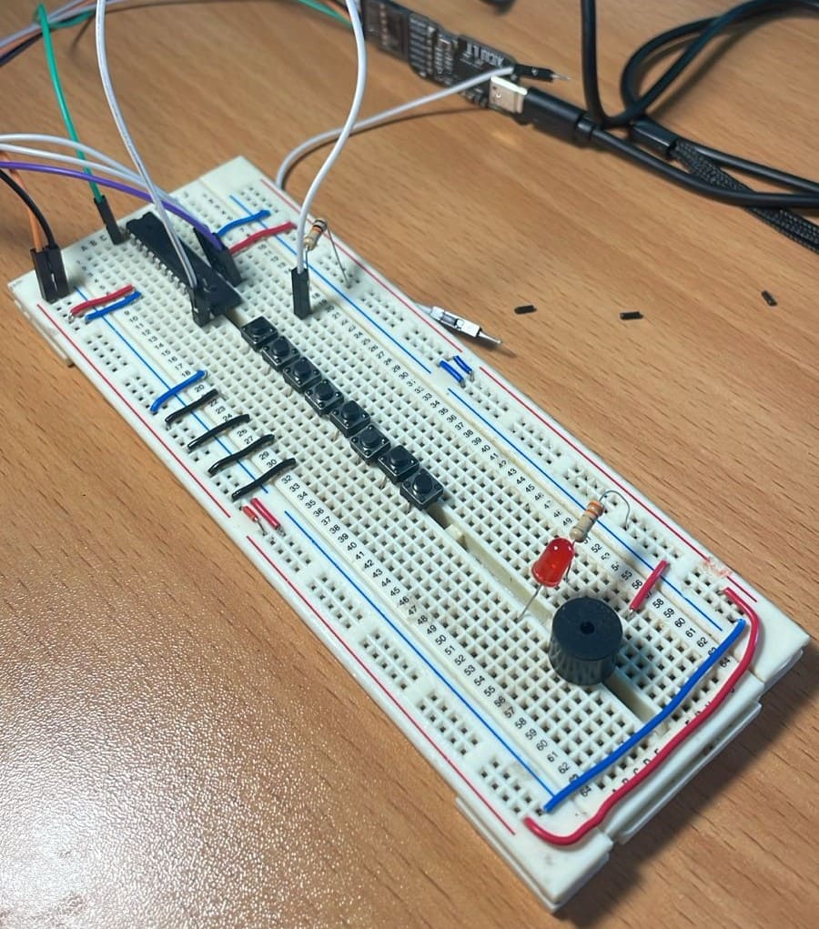
For one of my classes, I was asked to build a piano using an ATmega328P.
By configuring PWM correctly, I generated different frequencies so the buzzer could reproduce musical notes.
The system also adjusted both volume and octave using potentiometers connected to the ADC.
First, I assembled the hardware connections and arranged the protoboard to resemble a small piano layout.
My first attempt failed because the PWM configuration was incorrect, so the generated frequencies sounded distorted and out of tune.
I used an oscilloscope to verify the generated frequency and duty cycle.
After many iterations, I finally achieved the correct frequency and duty cycle for each musical note.
A friend helped me test the piano while I recorded the final demonstration.
Here is the final code used for the piano project:
#include <avr/io.h>
#include <util/delay.h>
#include <avr/interrupt.h>

uint8_t Top=0;
uint8_t nota=0;
uint16_t valor=0;
uint16_t octava=1;
uint16_t valor2=0;
float volumen=0.5;
int modo=0;
int matriz[10][1];
int i=0;

void interrupcion(){
PCICR|=(1<<PCIE0);
PCMSK0|=(1<<PCINT3)|(1<<PCINT4);
DDRB&=~((1<<PB3)|(1<<PB4));
sei();
}

ISR(PCINT0_vect){

if(PINB&(1<<PINB3)){
modo++;
_delay_ms(200);
}

if(modo==1){
PORTB&=~(1<<PB7);
TCCR1A&=~(1<<COM1B1);
}

if(modo==2){
PORTB|=(1<<PB7);
TCCR1A&=~(1<<COM1A1);
}

if(modo==3){
modo=0;
PORTB&=~(1<<PB7);
TCCR1A&=~(1<<COM1A1);
TCCR1A&=~(1<<COM1B1);

for(i=0;i<10;i++){
matriz[i][0]=0;
}
}

if(PINB&(1<<PINB4)){
i++;
matriz[i][0]=nota;
_delay_ms(100);

if(i>=10){
i=0;
}
}
}

void PWM1(){
TCCR1A|=(1<<COM1A1)|(1<<COM1B1);
TCCR1B|=(1<<CS11);
TCCR1A|=(1<<WGM11);
TCCR1B|=(1<<WGM12)|(1<<WGM13);
DDRB|=(1<<PB1)|(1<<PB2);
}
The full program manages ADC readings, interrupts and PWM signal generation to create different musical notes and volume levels.
This week’s work directly supports the development of my final project.
Building the piano helped me understand how important PWM and ADC configuration are in embedded systems.
That experience gave me a better understanding of timers, signal generation and hardware-level programming.
While reviewing the ESP32 datasheet, I focused on specifications related to my wearable device.
Sleep modes are important for battery life optimization.
ADC functionality will be used for heart rate sensor integration.
PWM control will allow smooth vibration feedback for the wearable.
Overall, this week helped me move from simply programming to making informed technical decisions for my final project.