

16. System Integration
This week I planned, designed, fabricated and assembled my final project.
System Sketches
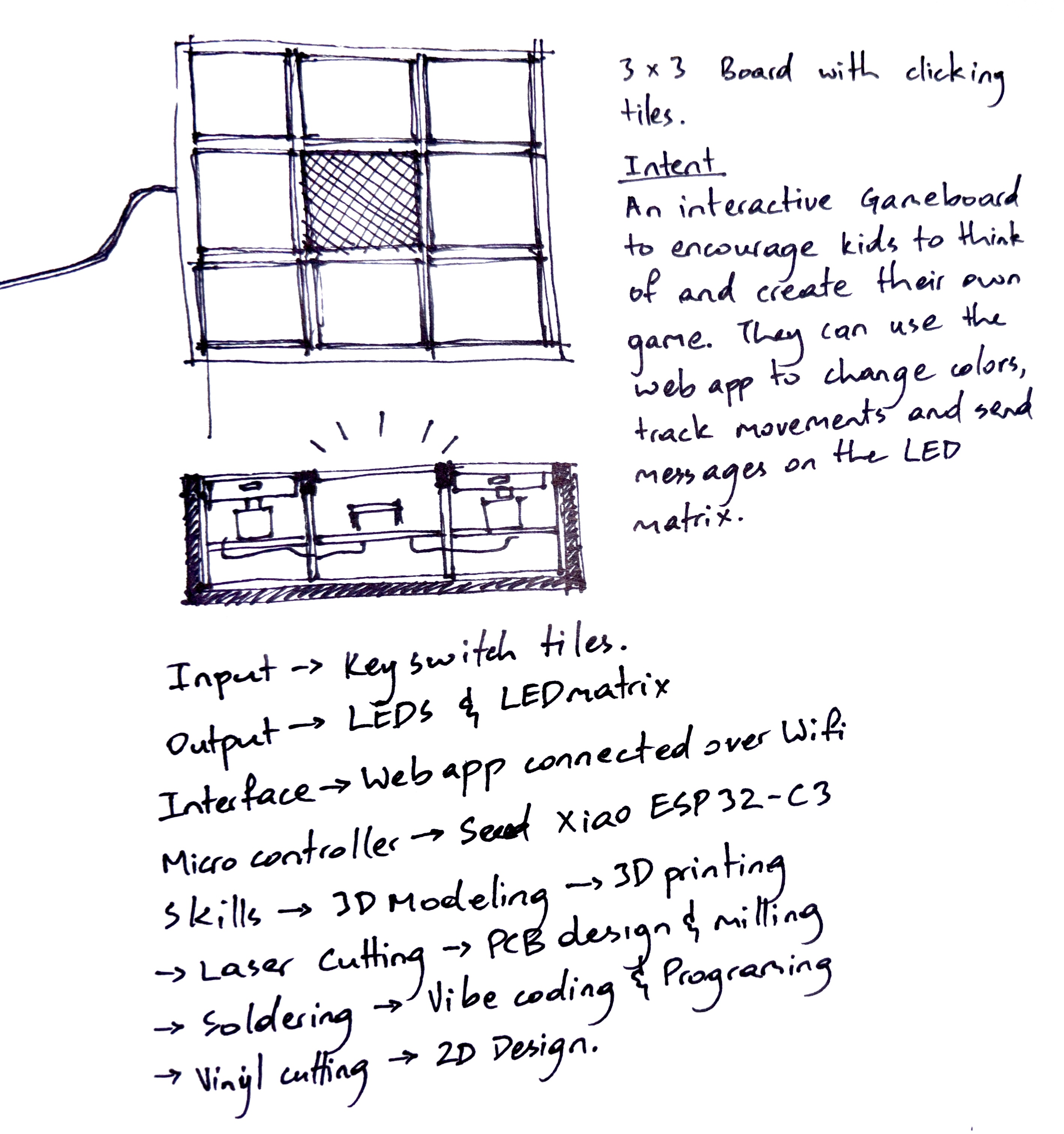
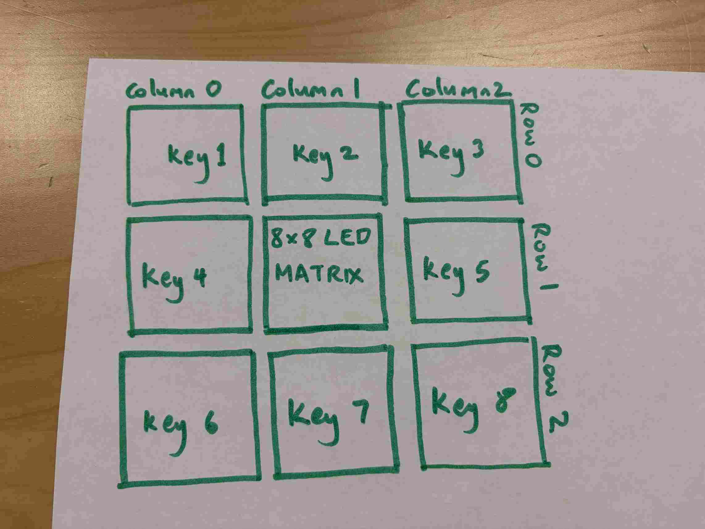
These sketches show how I was thinking aboutht the components and functions of the system. A 3x3 board with clickable inputs in the 8 outer squares, compartments for the inner components, a layer to organize the wiring, partition walls that offer structure and light isolation and a plan for how the physical form will influence the software functions.
Layered Plan of the System Integration
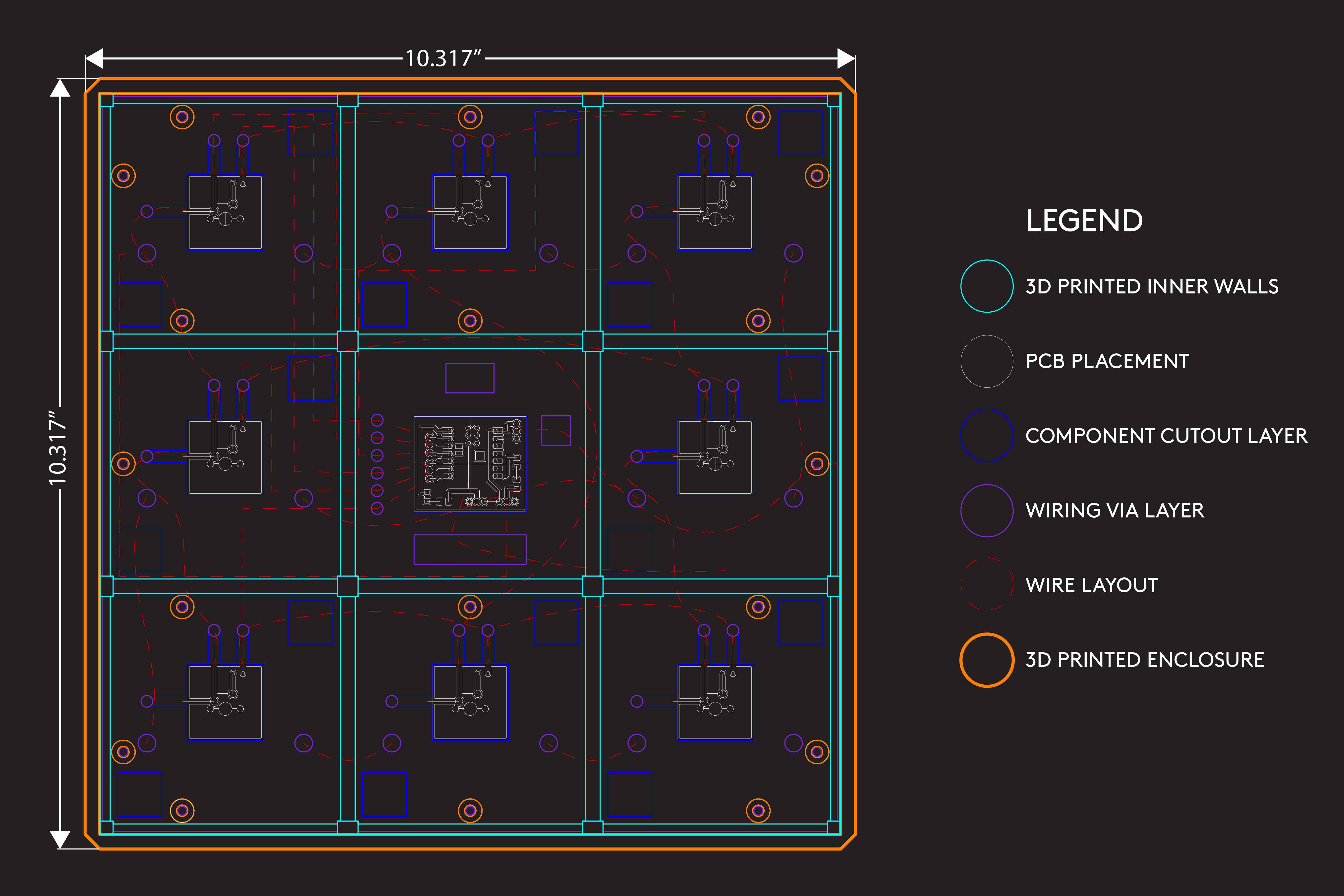
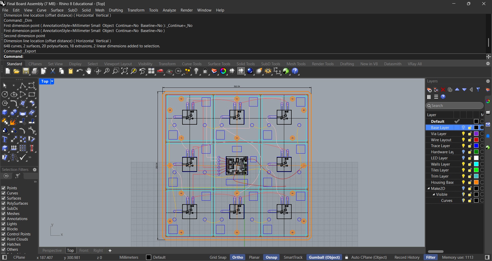
I used Rhino 8 to layout each layer of the project and how the components and wiring would be secured.
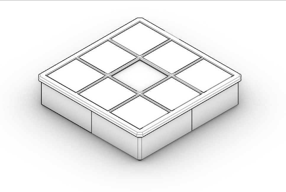
The layout was then turned into a 3D model which I could use to fabricate the physical components.
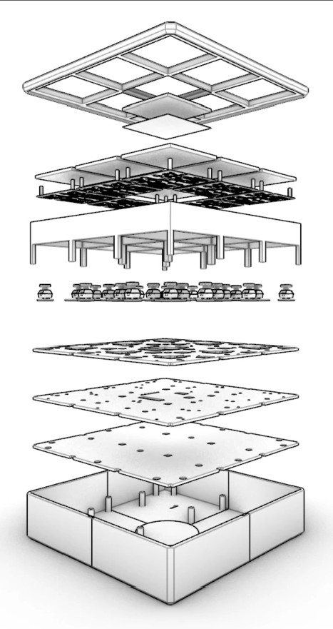
This exploded perspective view shows how each component aligns and works together to form a unified system. I relied heavily on my architectural background for this design.
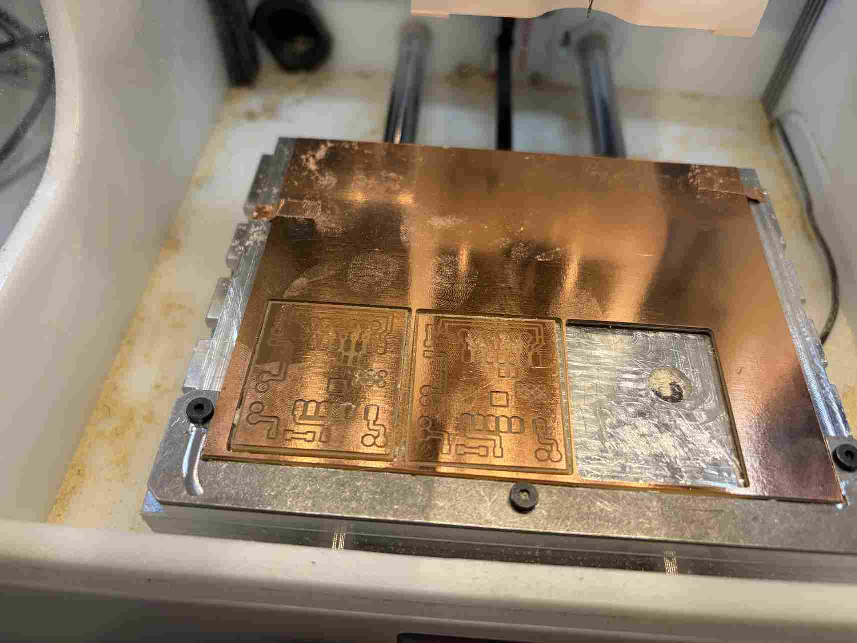
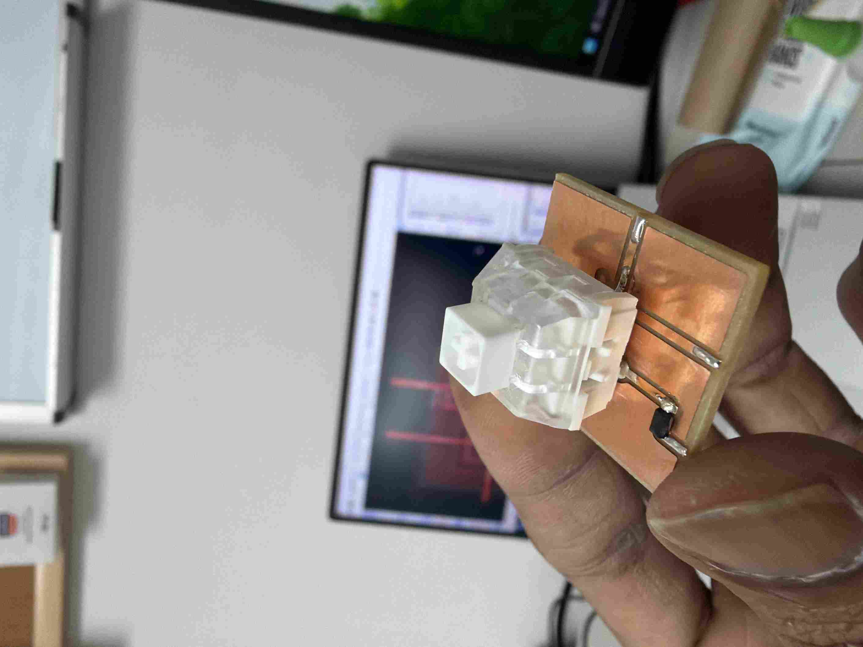
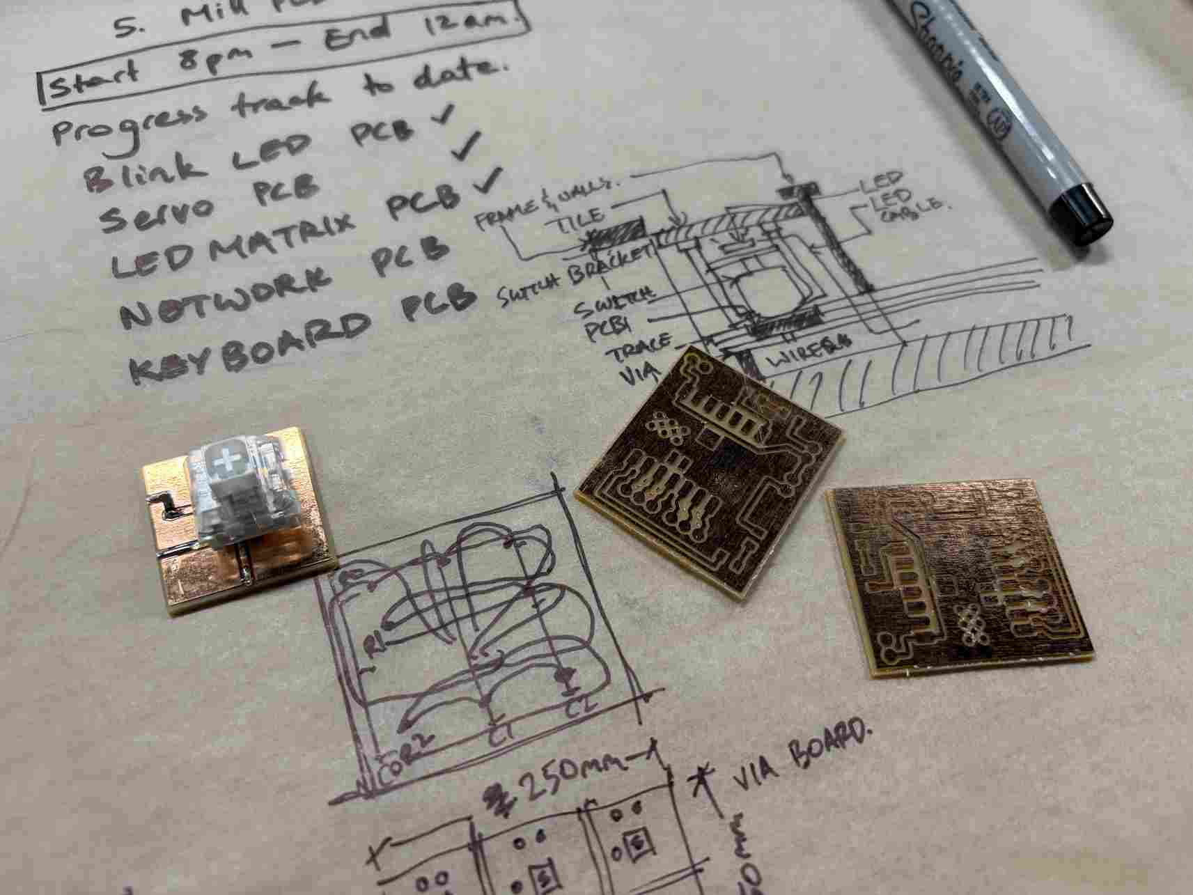
I designed and milled the PCB using the Bantam Tools CNC machine.The key switched were glued and soldered in place along with the diodes. The pins for the switches were clipped to an appropriate length to be surface mounted.
In this sketch, I was still working through the layout and wiring before the final design seen above.
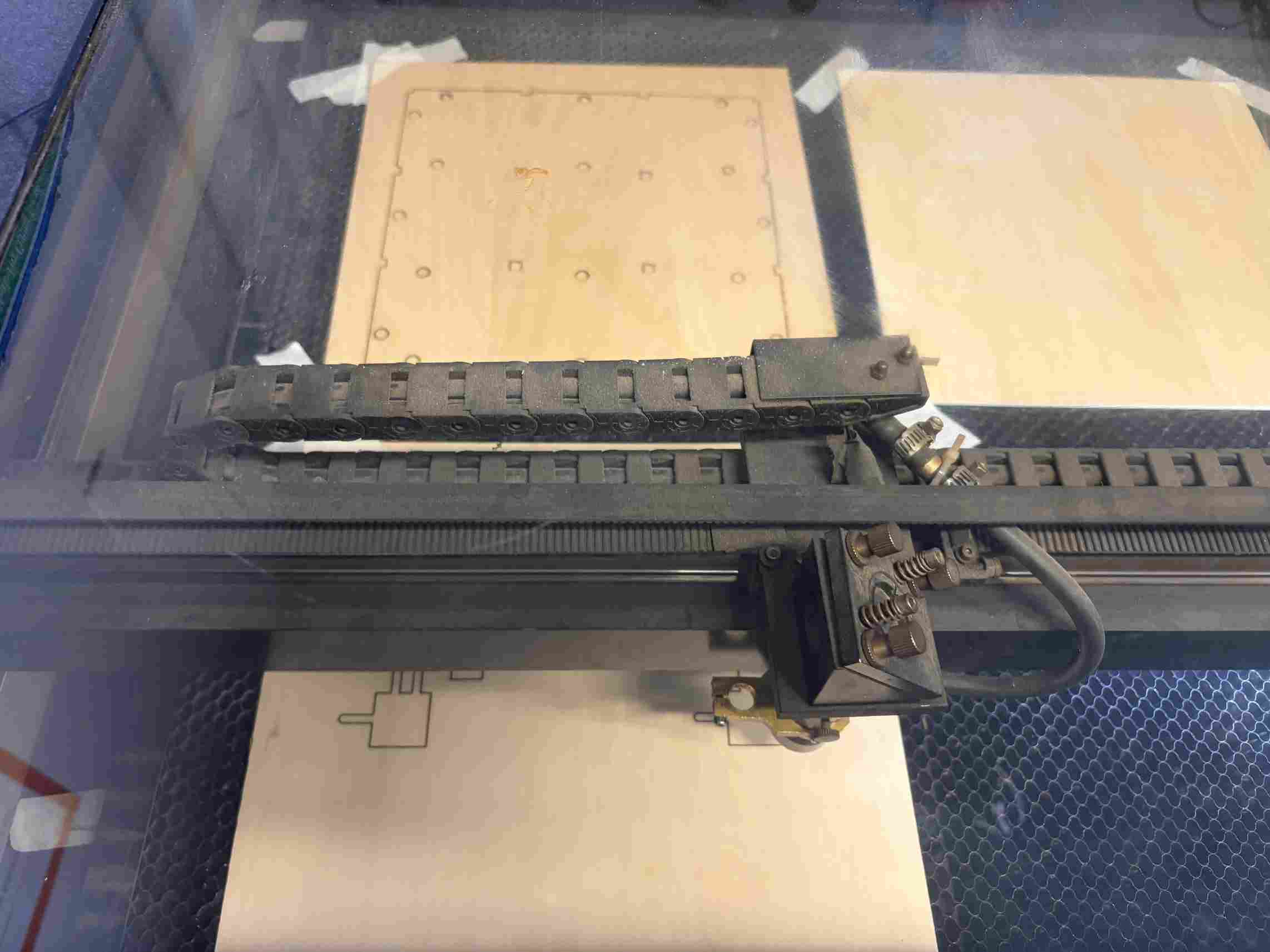
I laser cut the inner layers that align the base and support the other components. This was cut out of basswood.
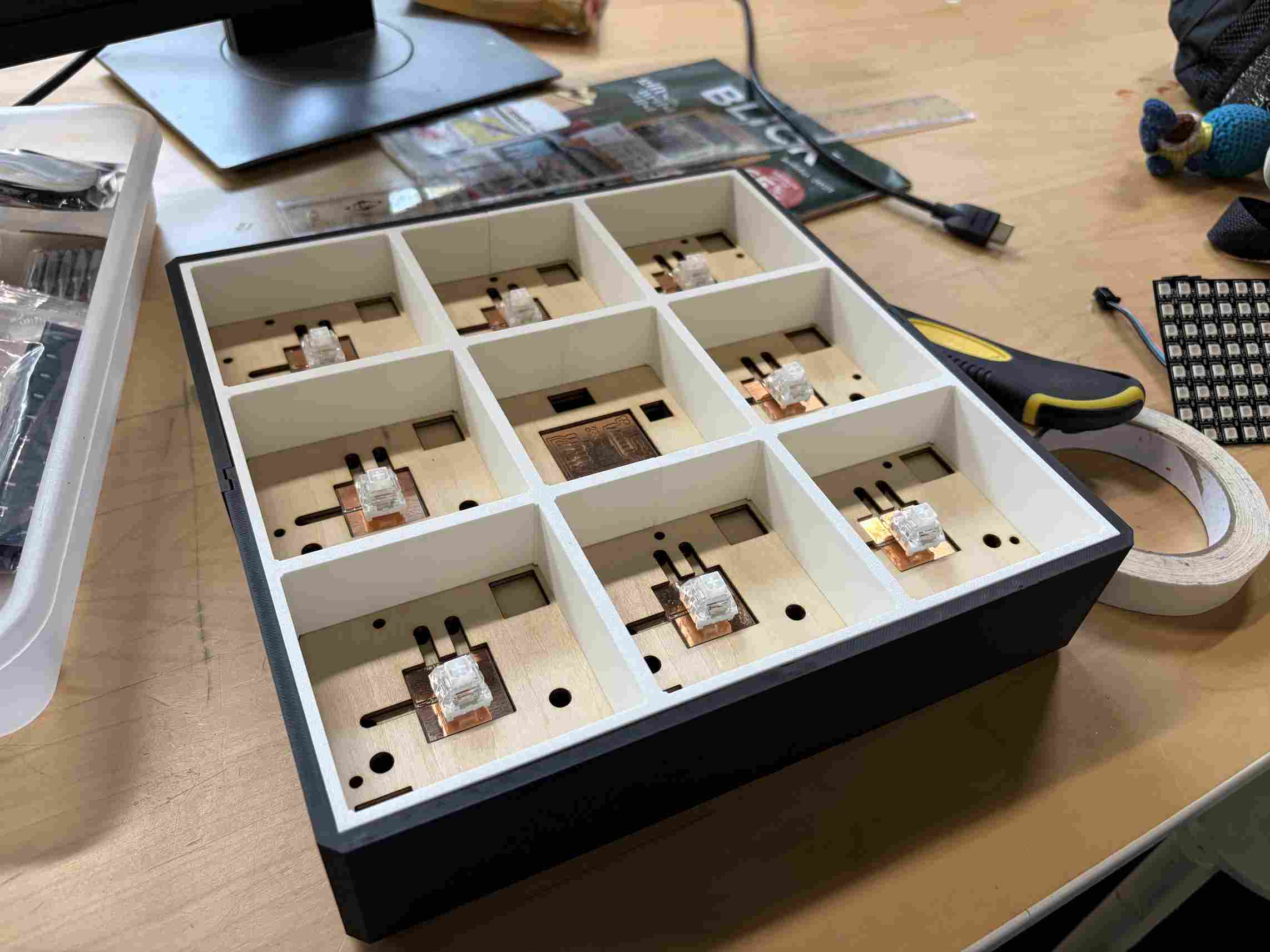
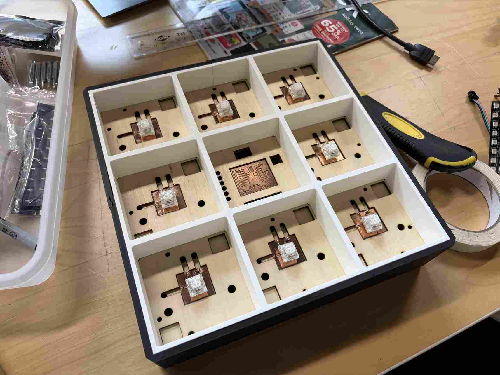
Dryfitting the parts to make sure they align properly before final assembly.
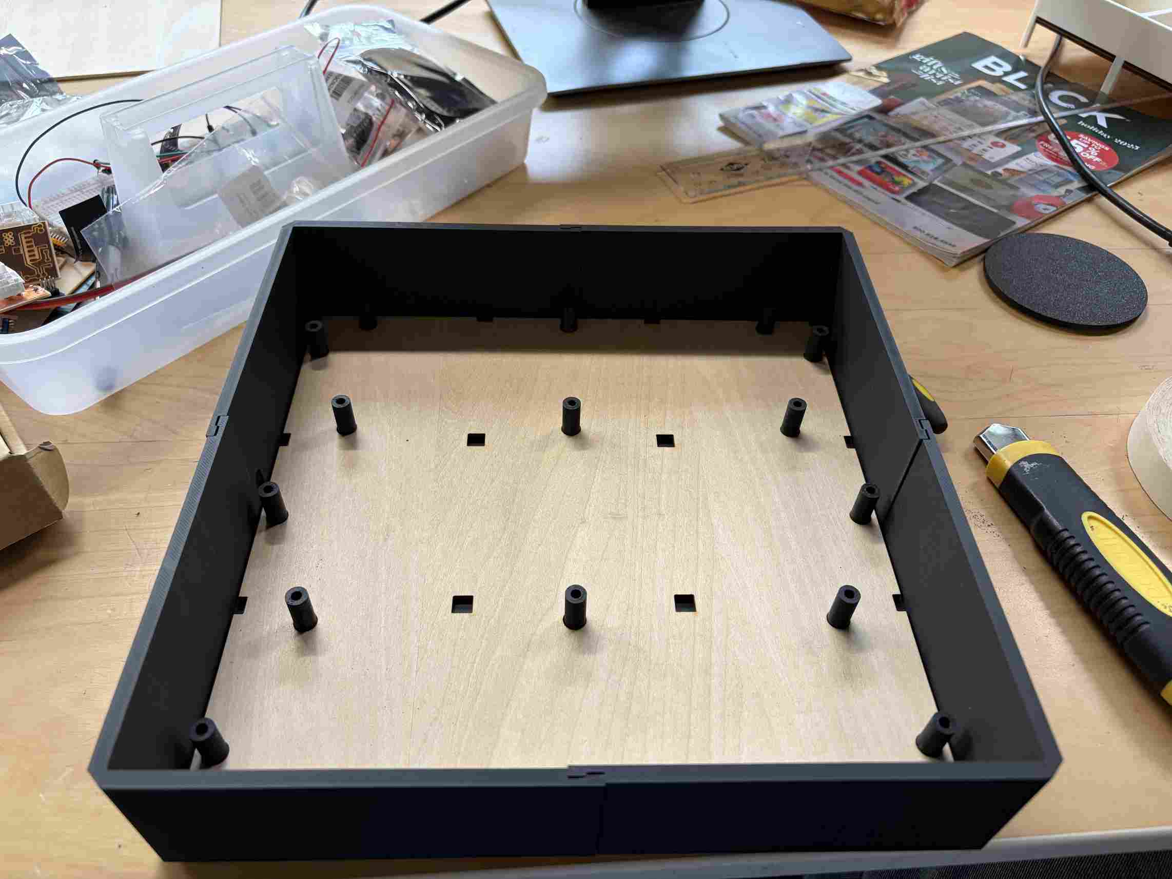
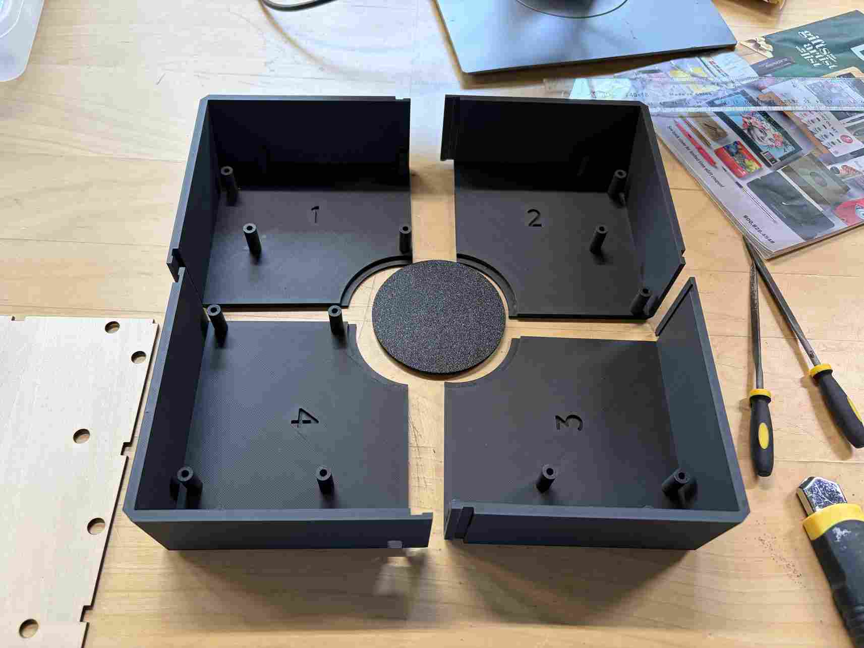
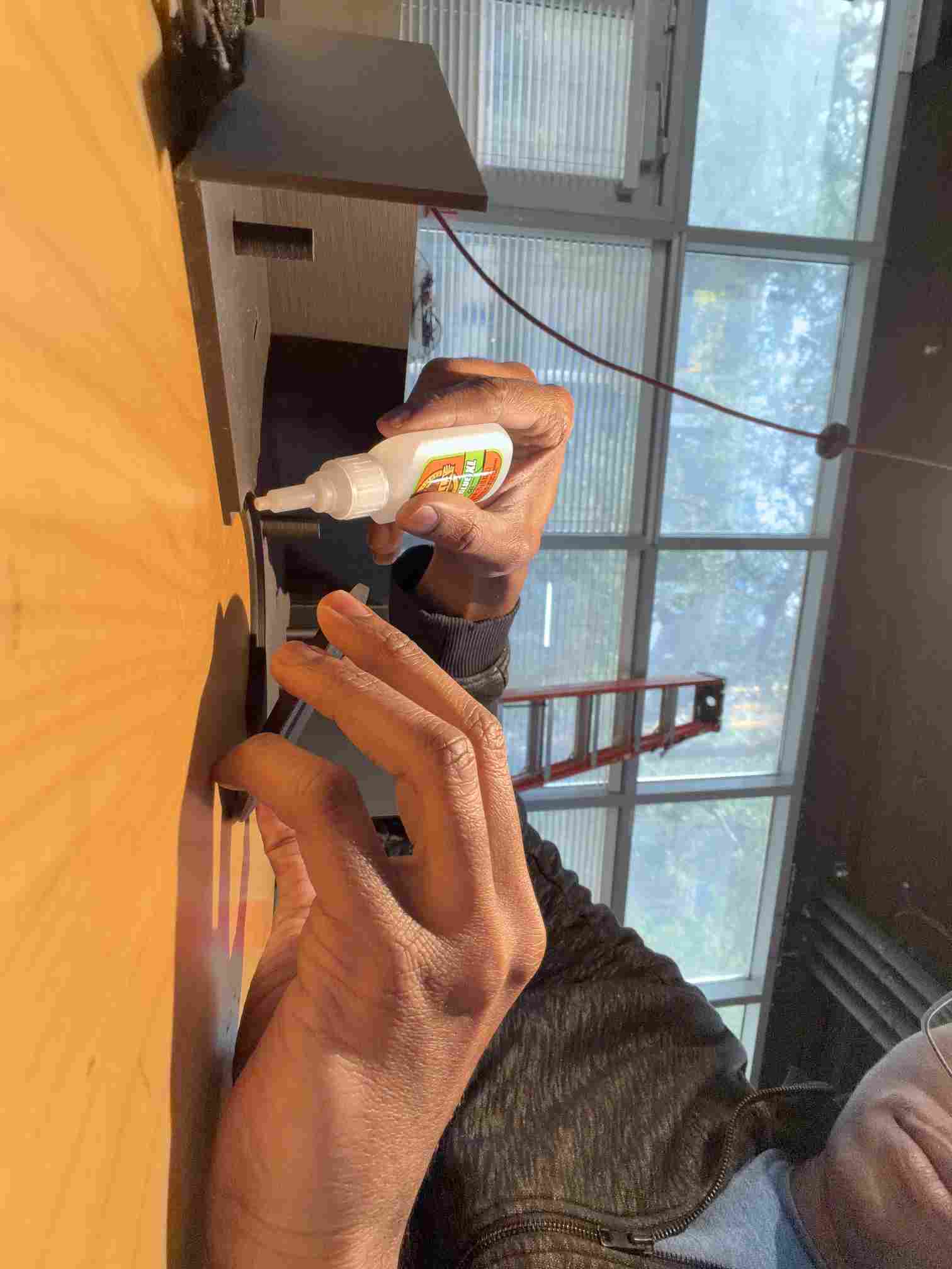
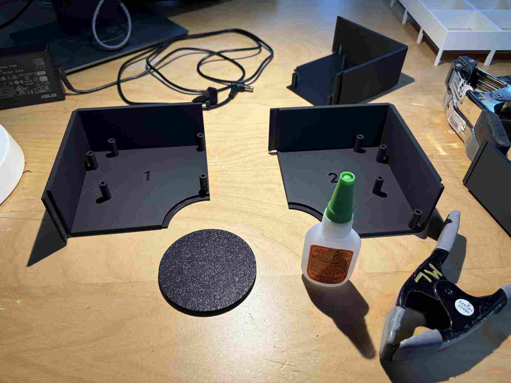
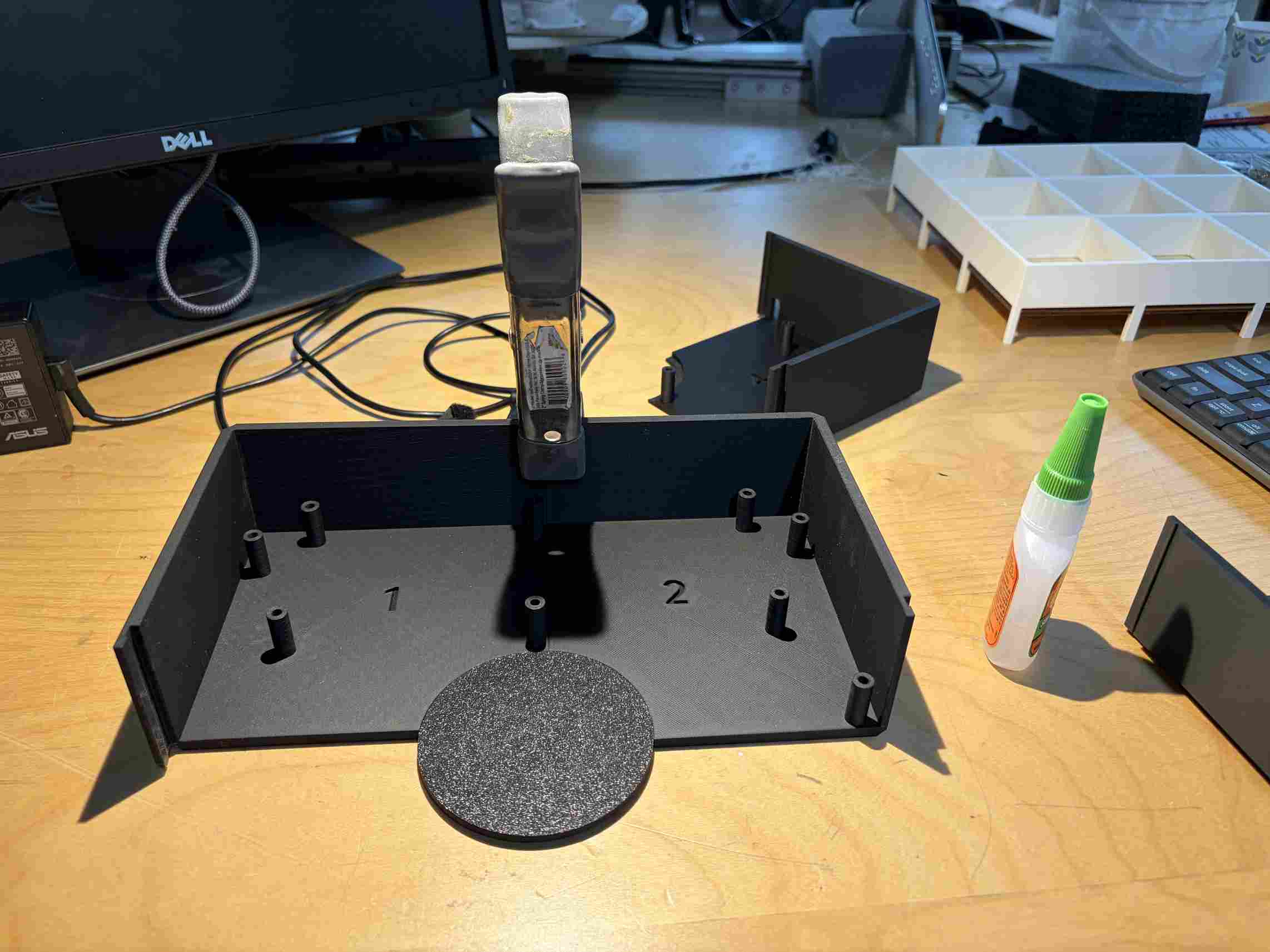
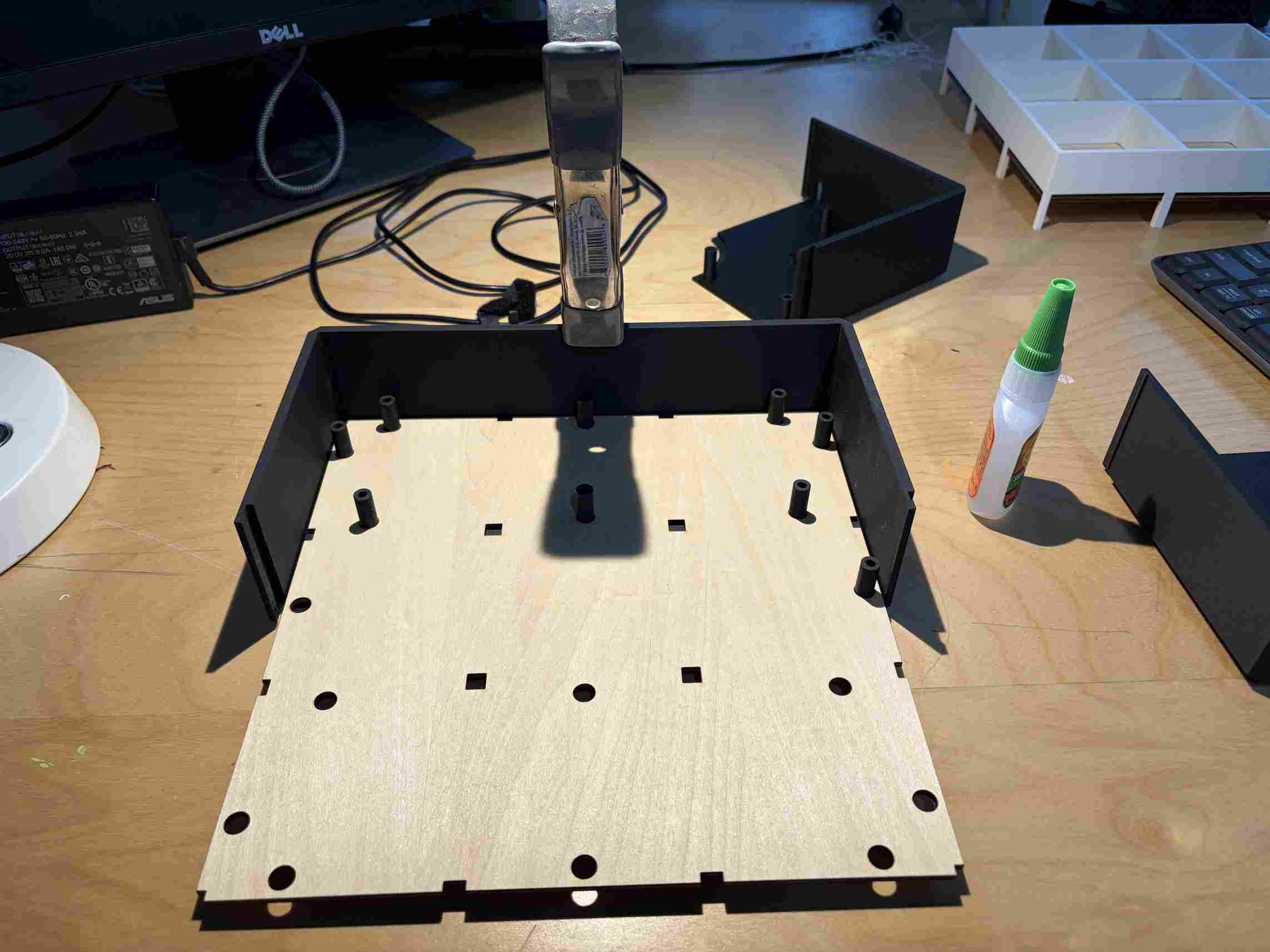
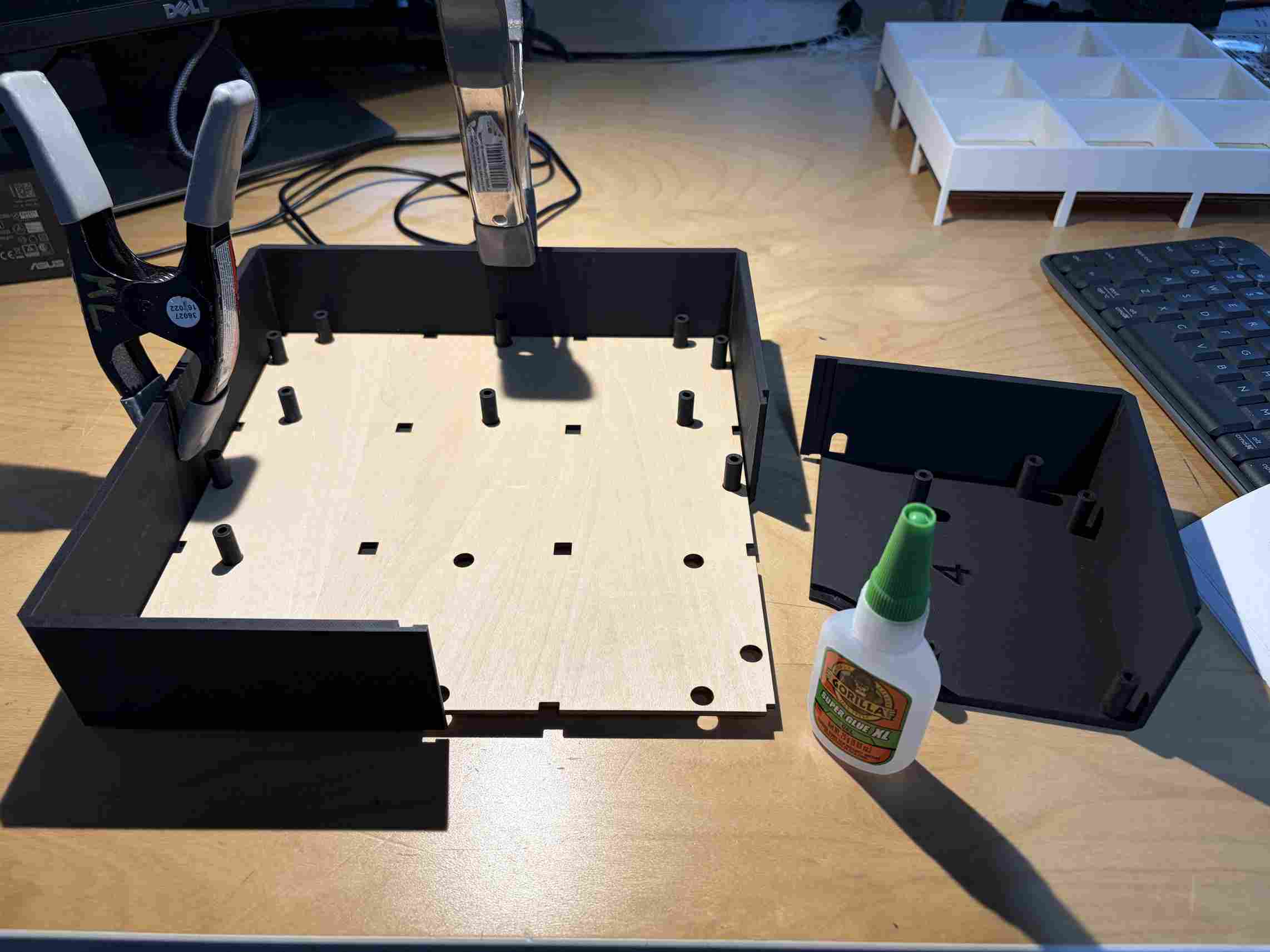
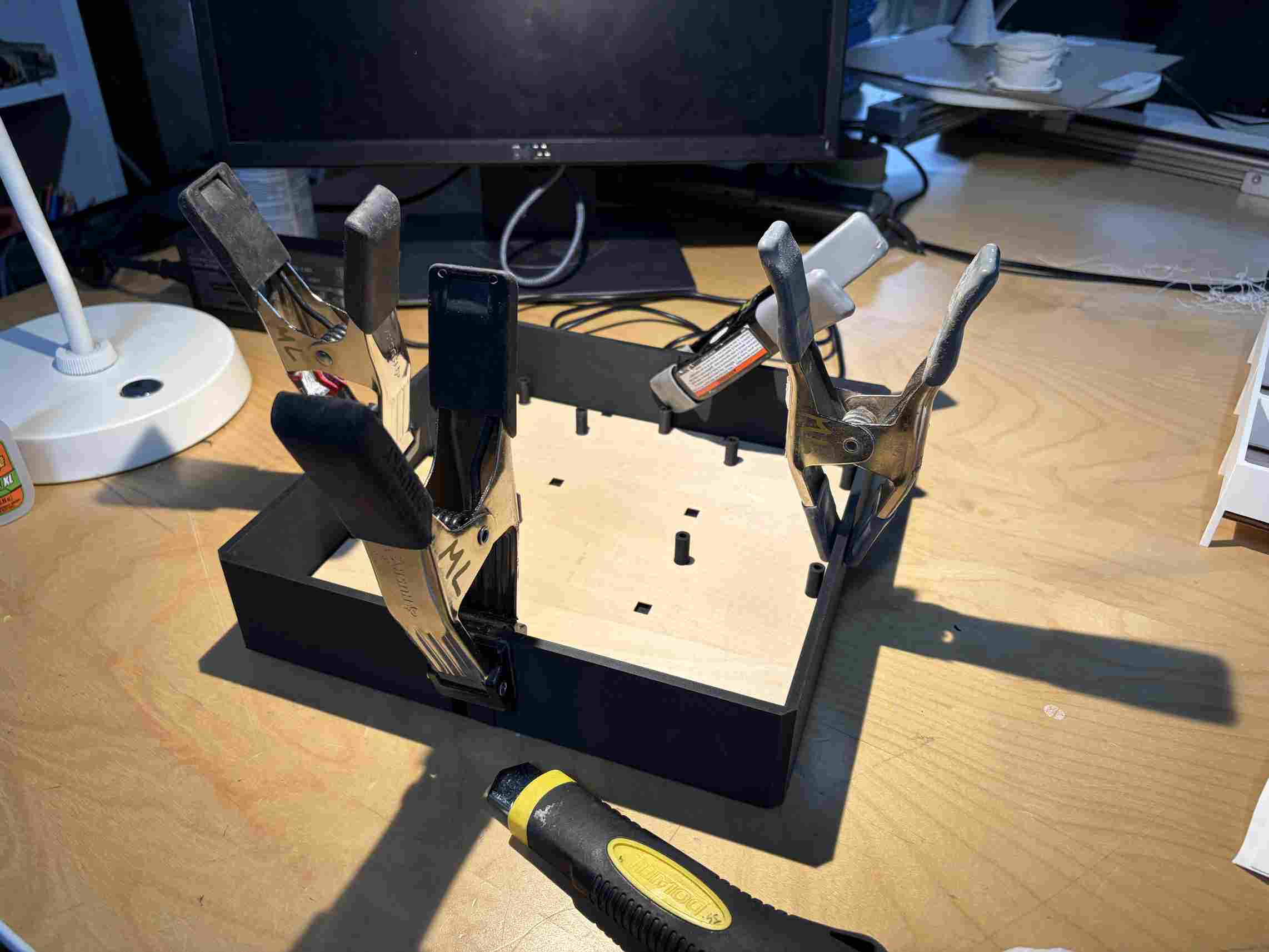
The parts came together like a puzzle but I was able to align them and used super glue for a fast and secure bond. The clamps applied pressure while the glue set.
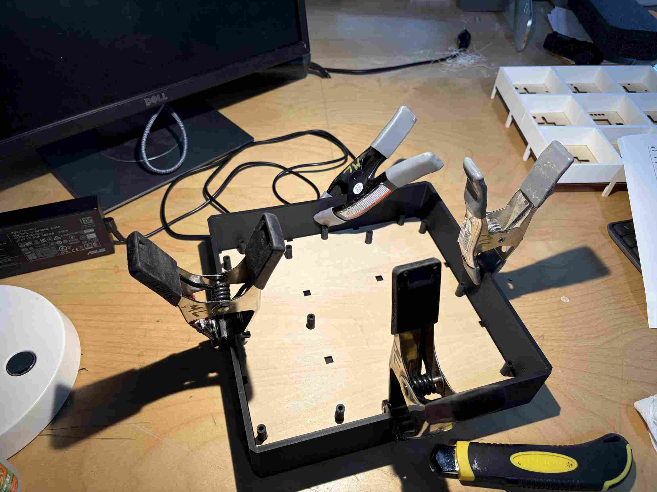
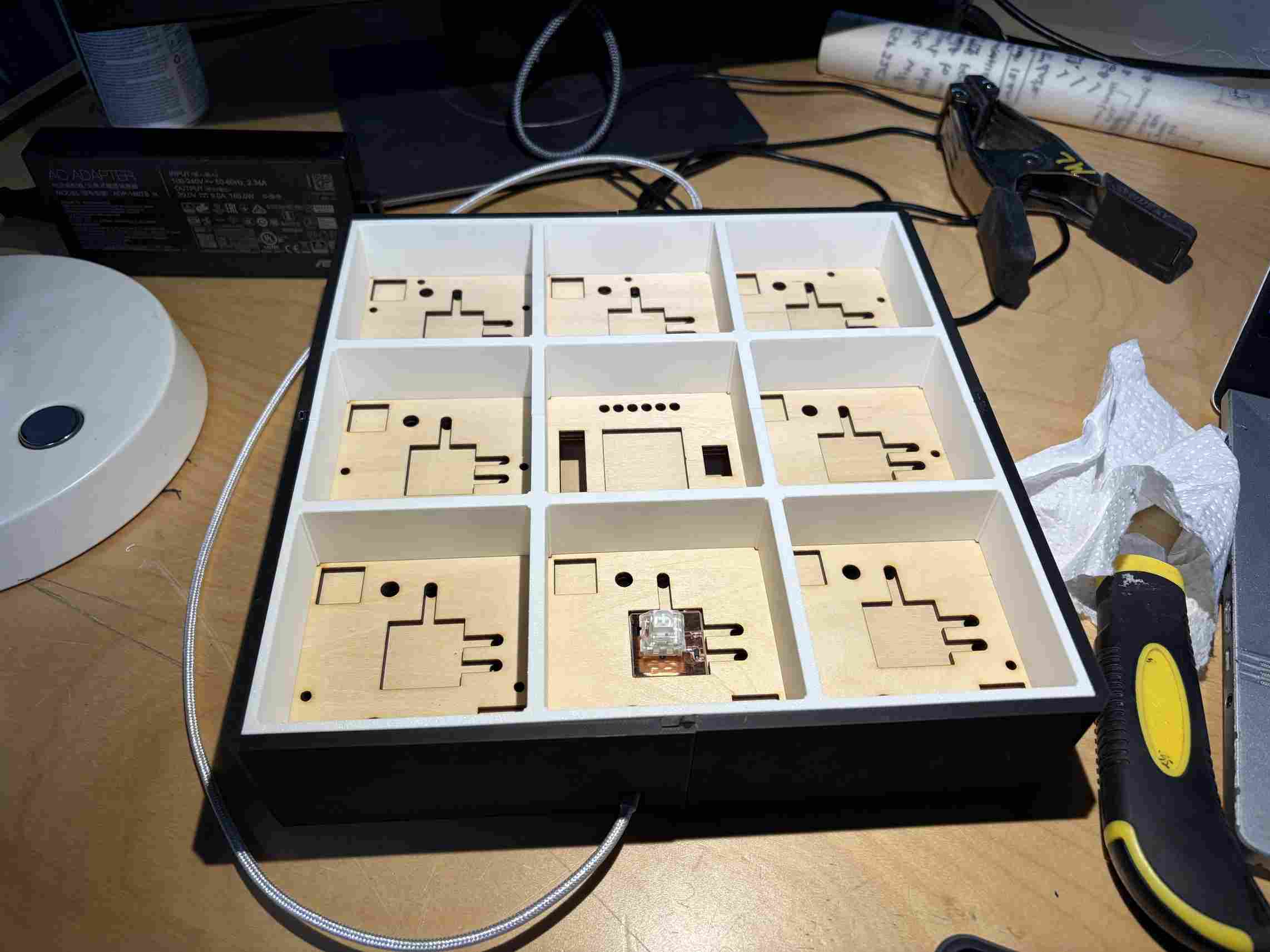
The assembly was so exact that it became very difficilt to remove the middle layers with the 3D printed walls and columns once in place. I however had to do so periodically to ensure that there were no misalignments with each step.
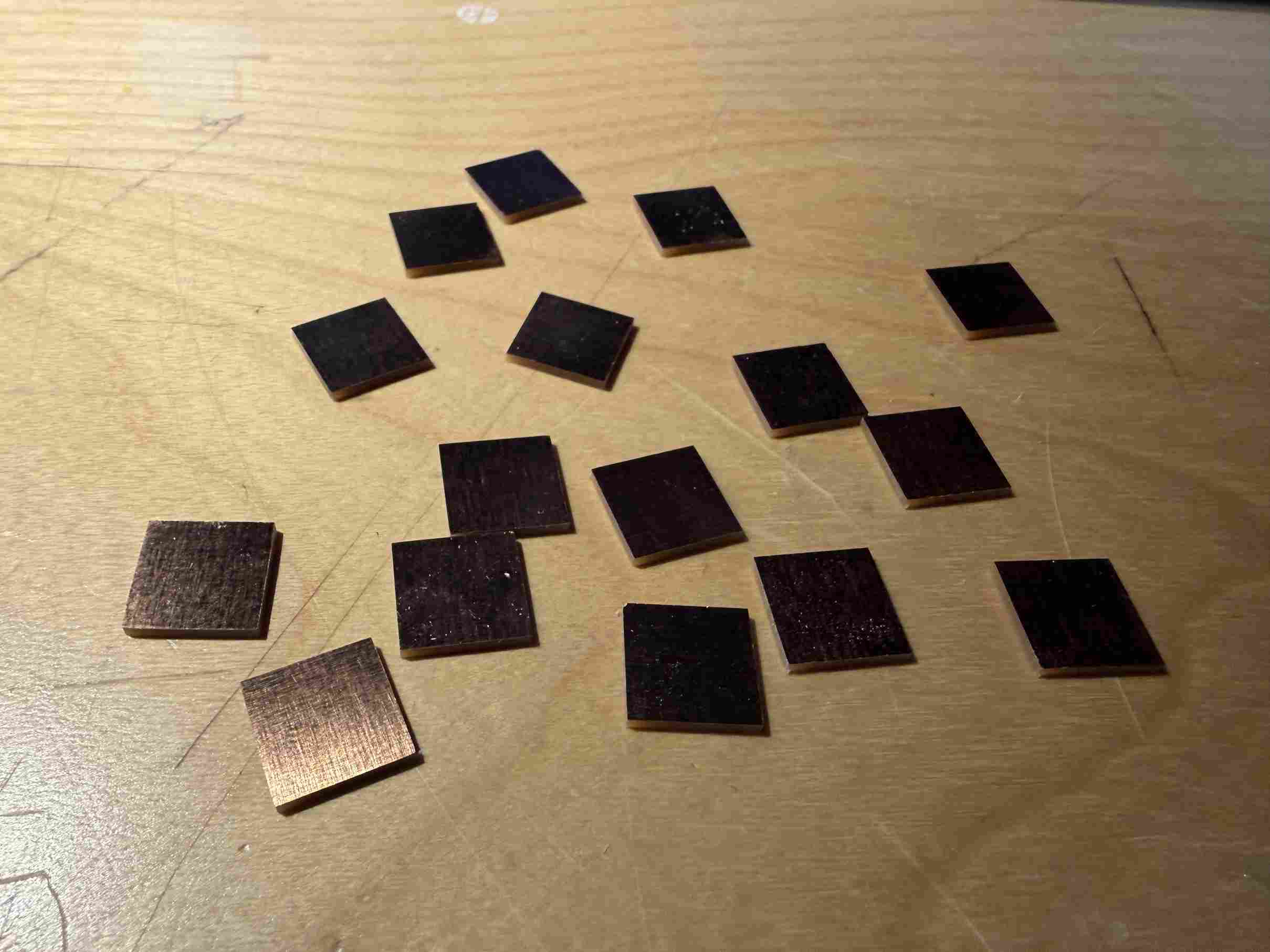
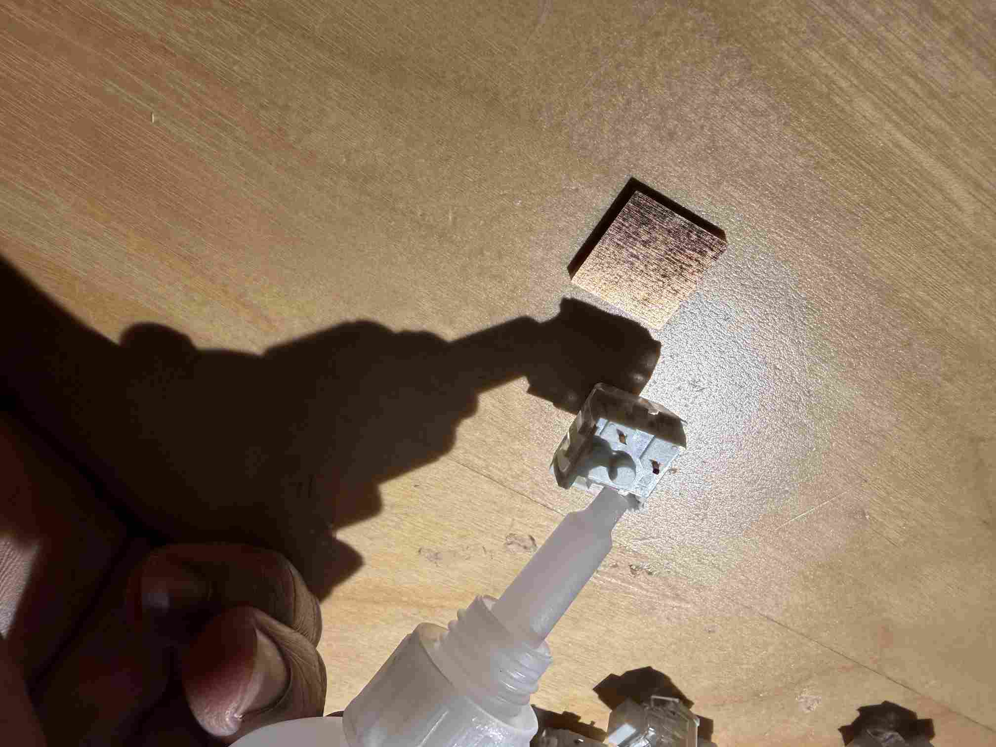
Each of the outer squares has 2 "dummy switches" to add stability to the player tiles. This improves durability and the game play experience.
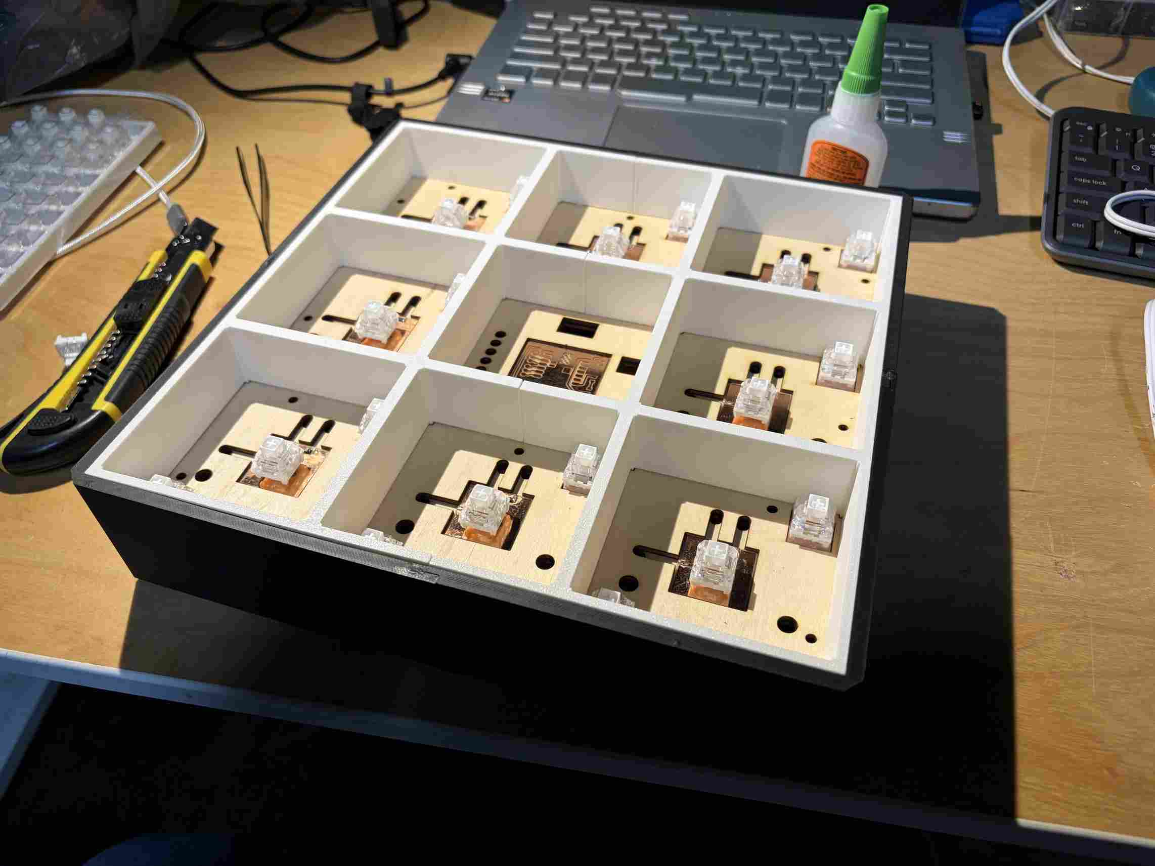
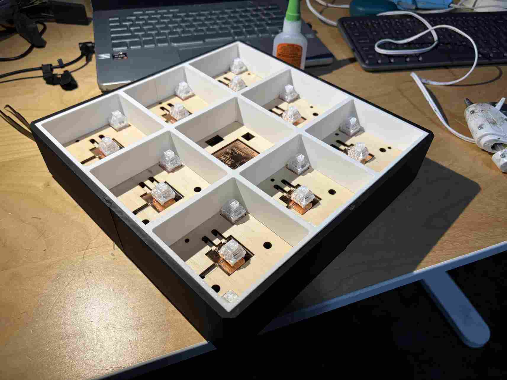
Everything in place.
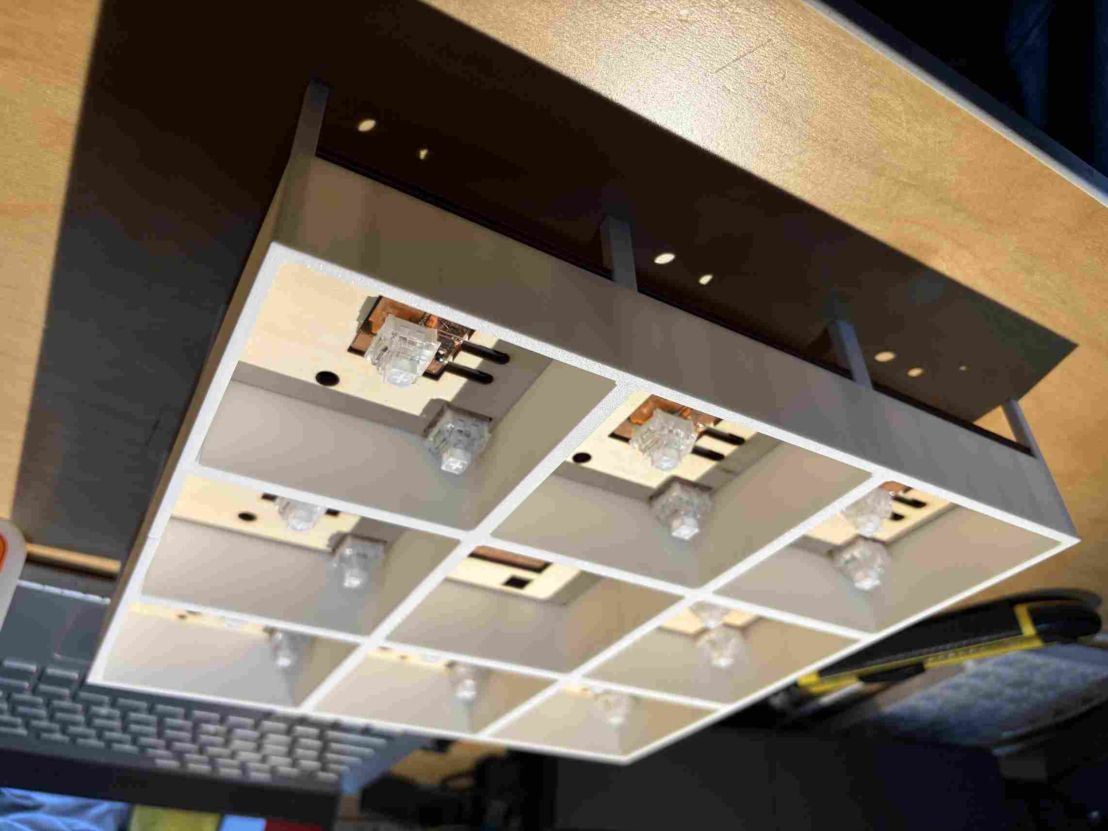
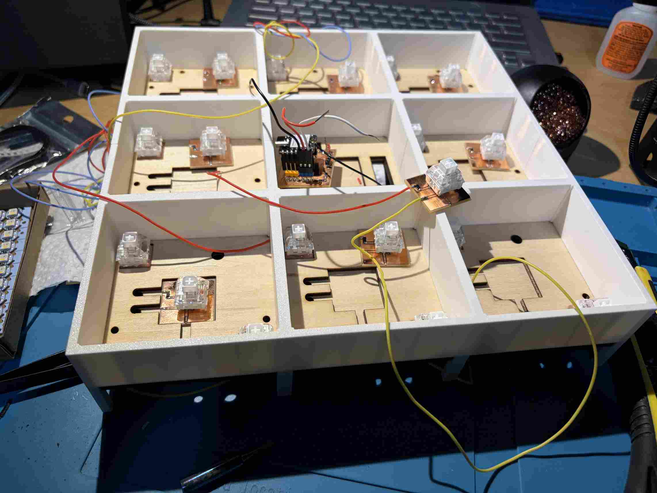
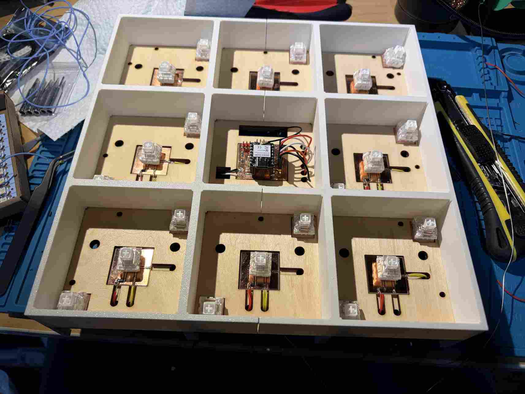
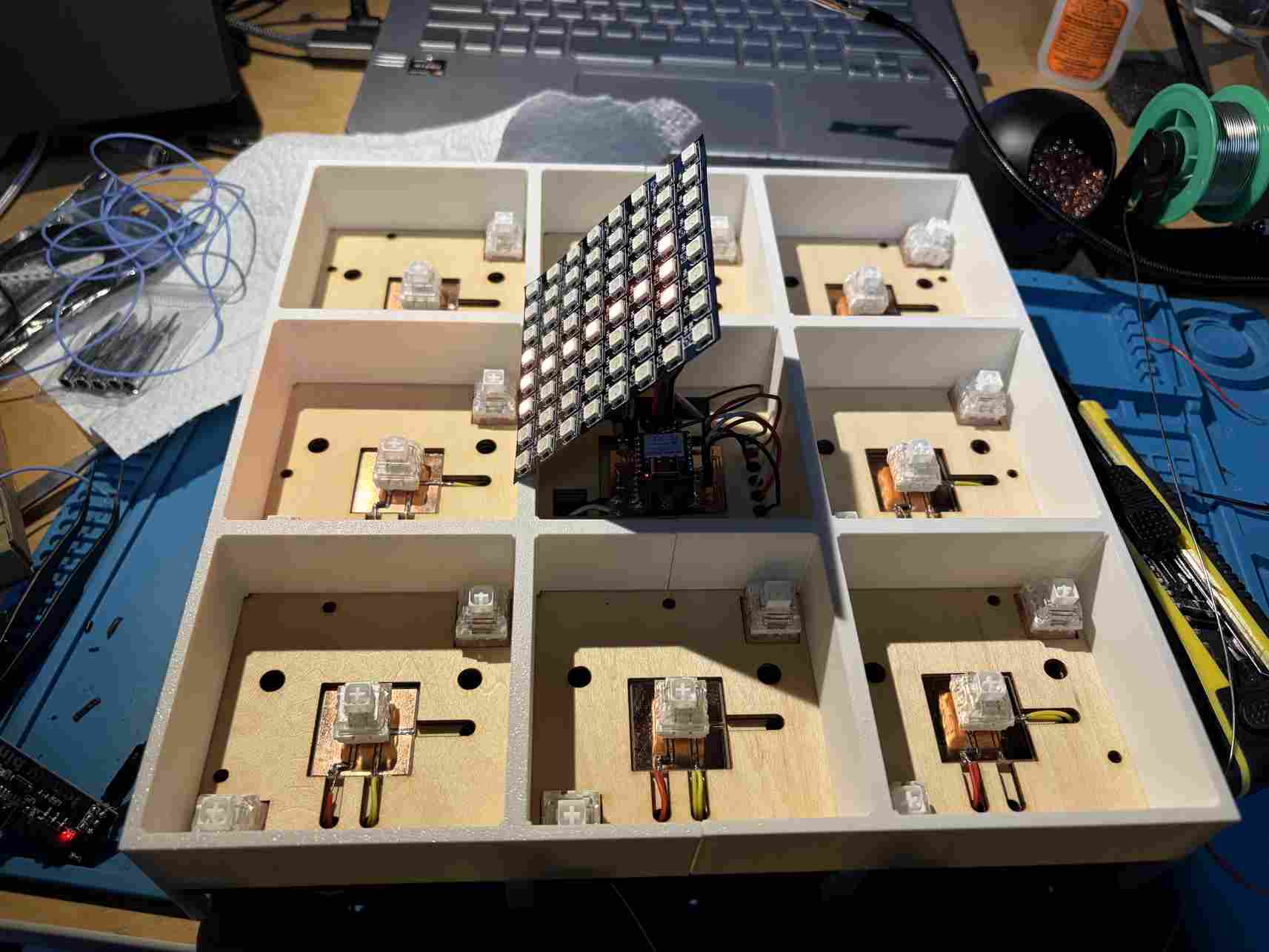
Next was wiring the boards. I ran the wires under the basswood to keep them organized. This required access to the underside. This worked well.
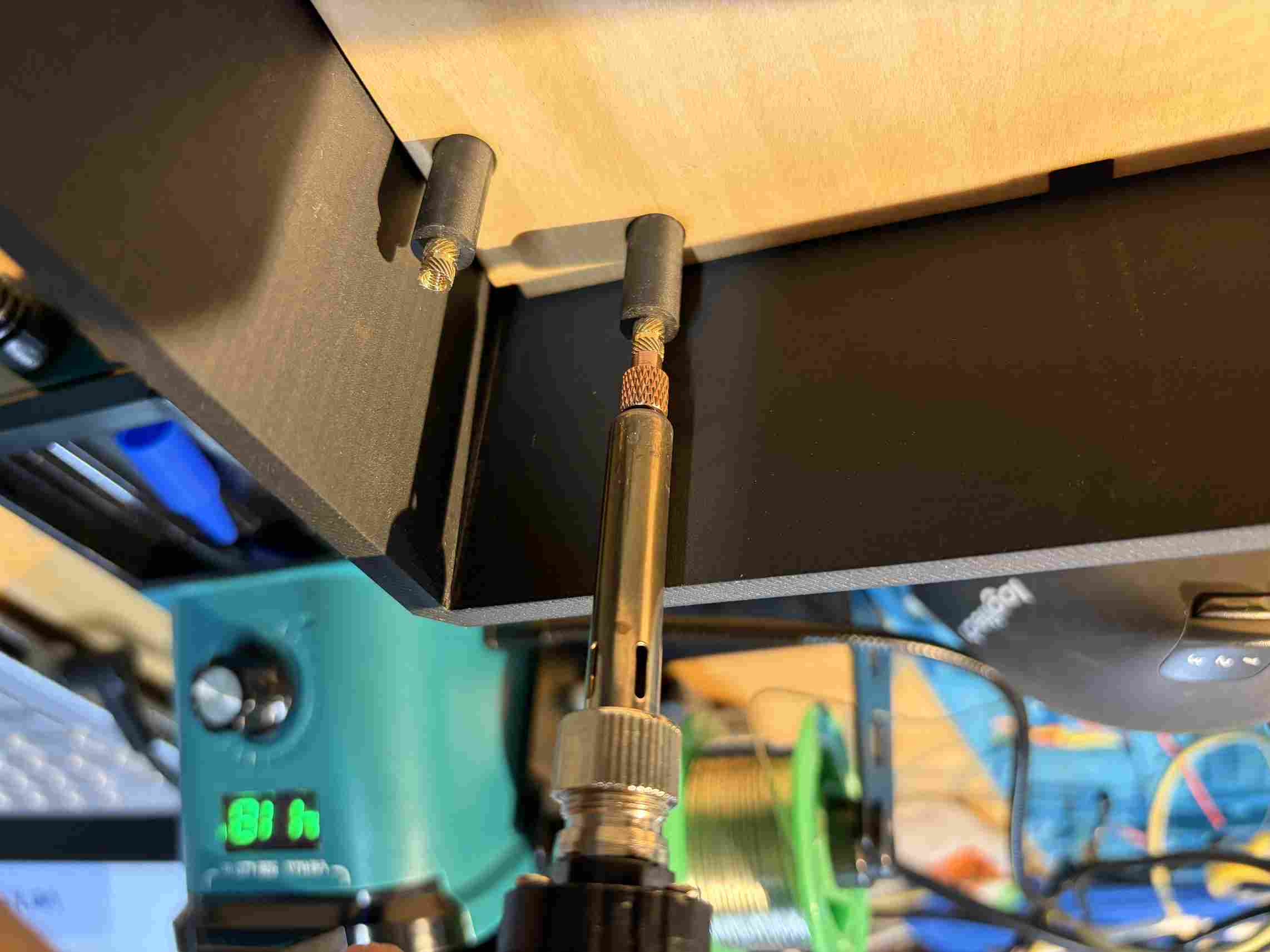
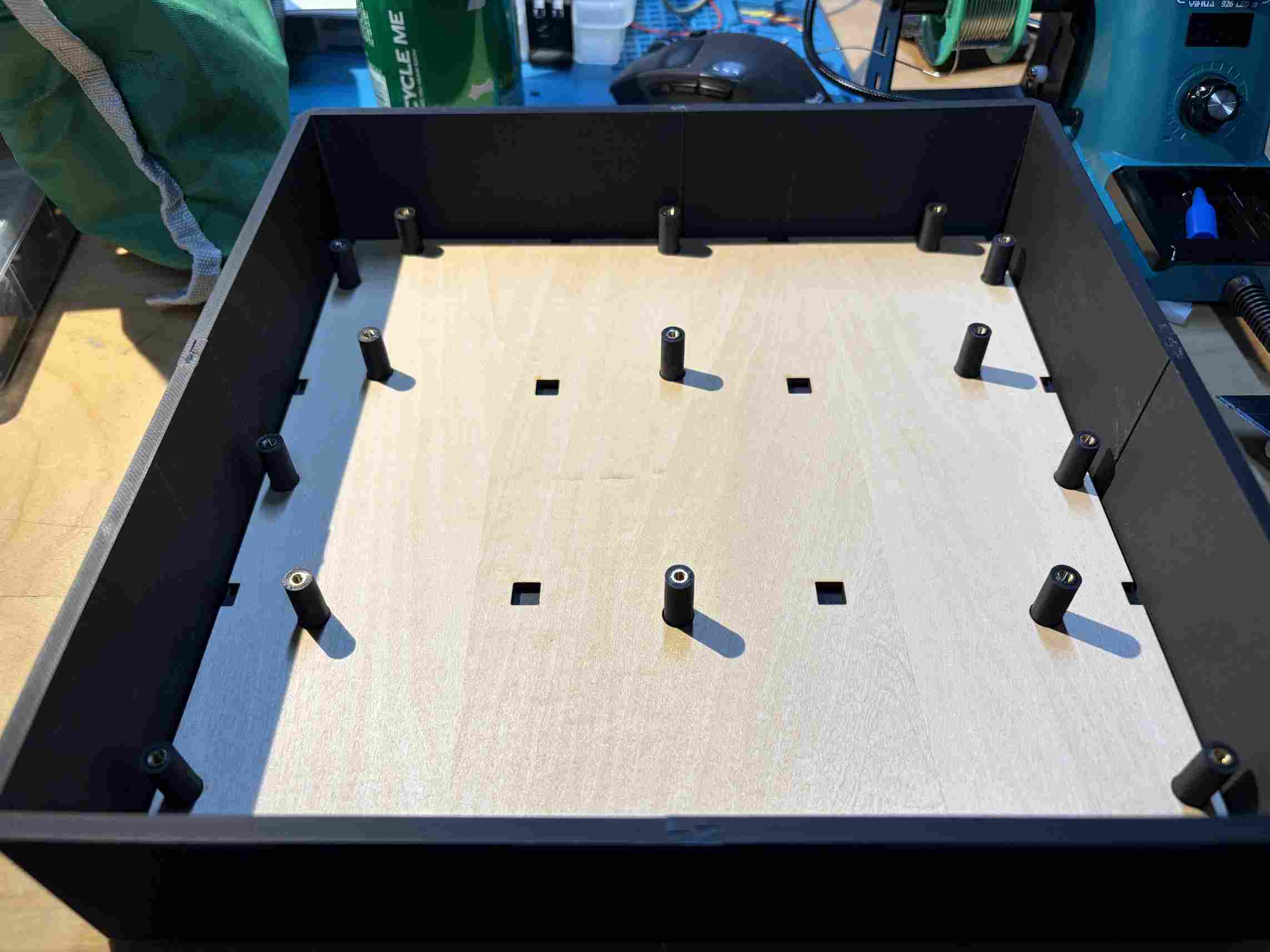
Using a soldering iron, I added heated inserts to the 3D printed screwholes.
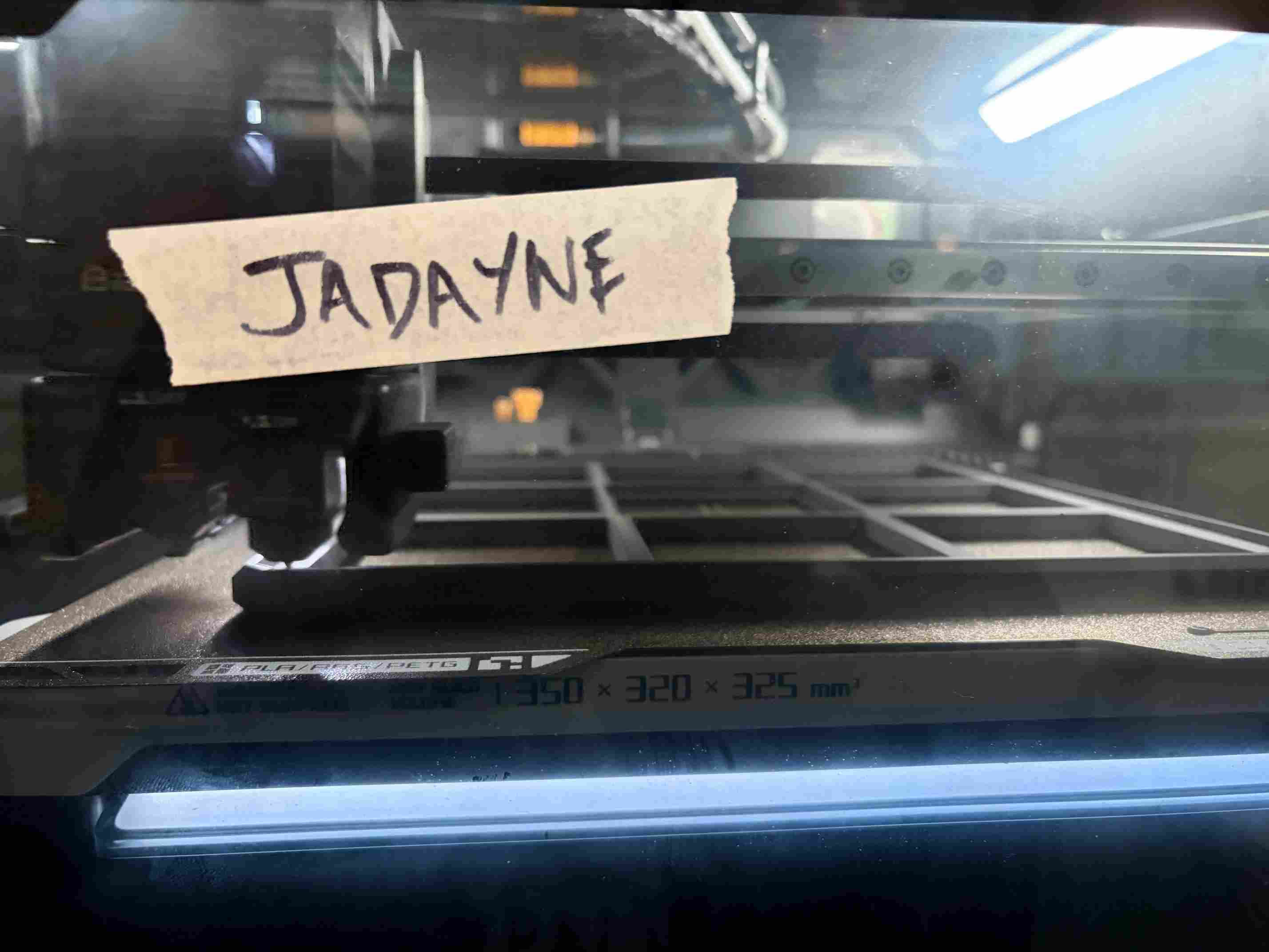
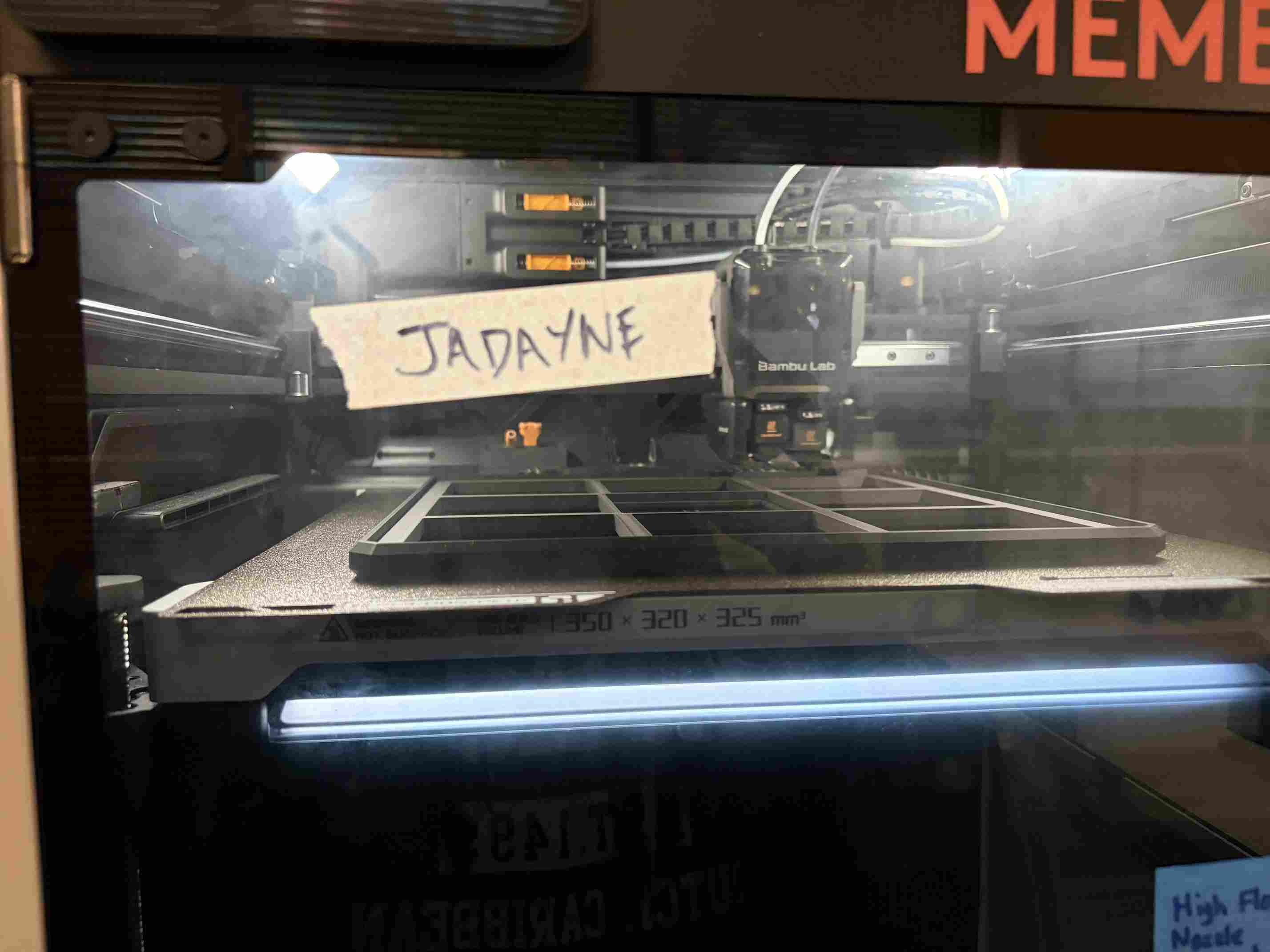
My first round of 3D printing was done using Bambu Lab's P1S printers. Their 10"x10"x10" bed capacity meant that I needed to split the base of my project. When I was printing the top of the enclosure, I was able to use the H2D printer which has a 13.78"x12.60"x12.80" capacity. This allowed me to print the component in 1 piece for a more professional finish.
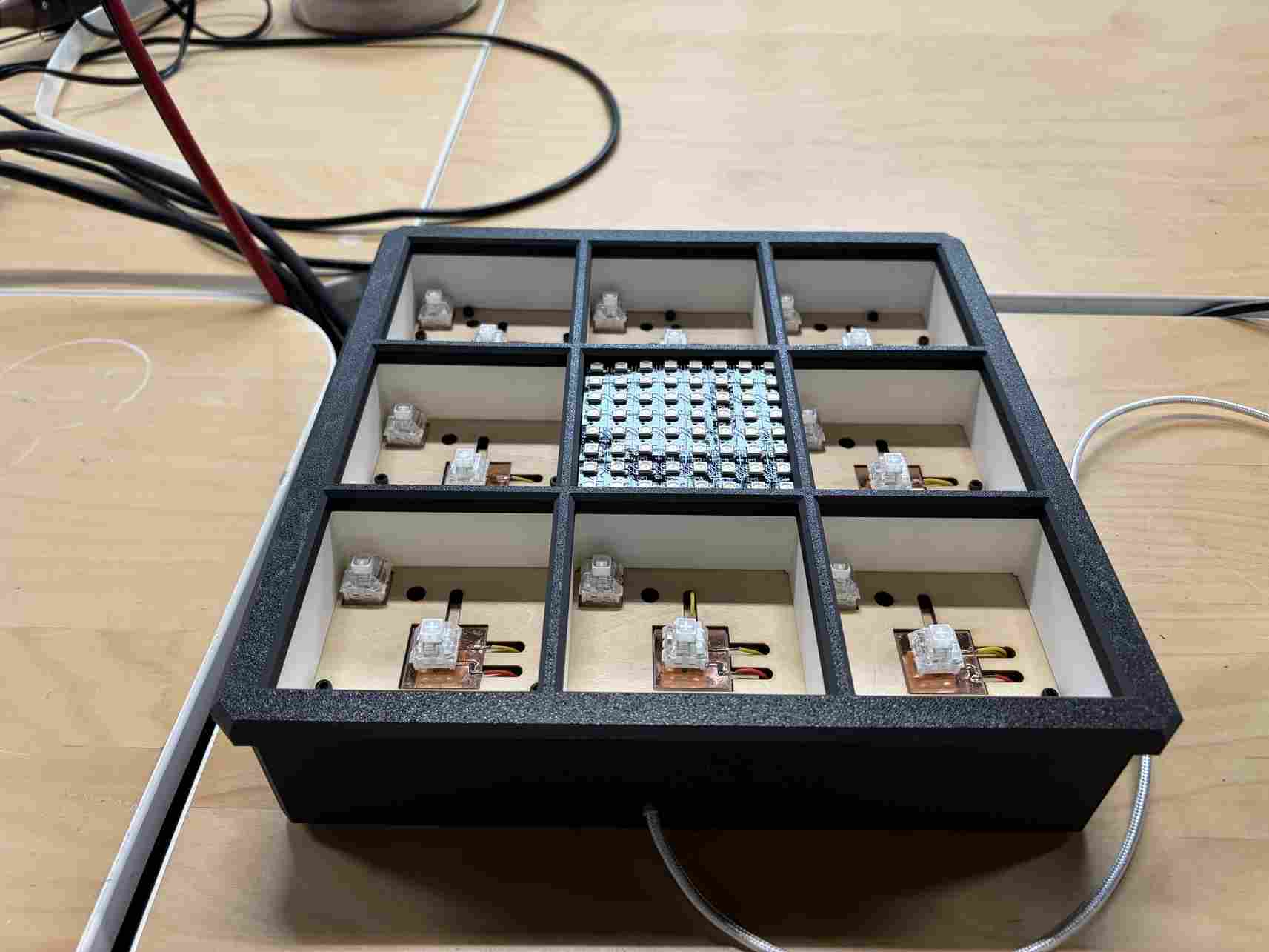
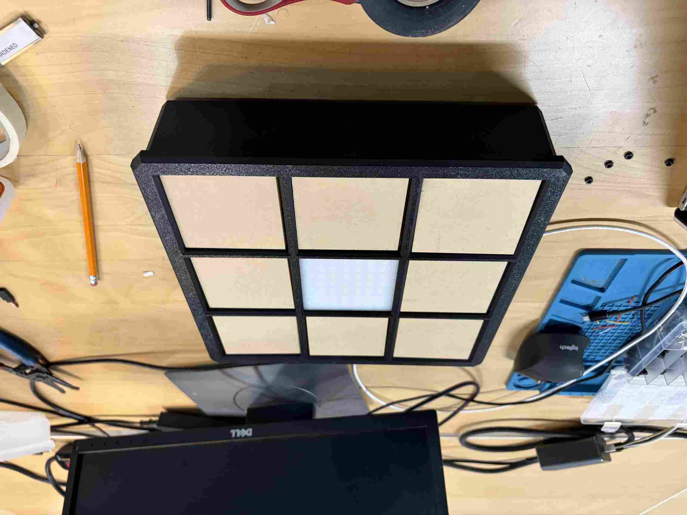
This is the enclosure assembled. You can also see the USB-C cable neatly coming from a small opening in the side. This is connected to a USB-C power supply embedded in the wire compartment.
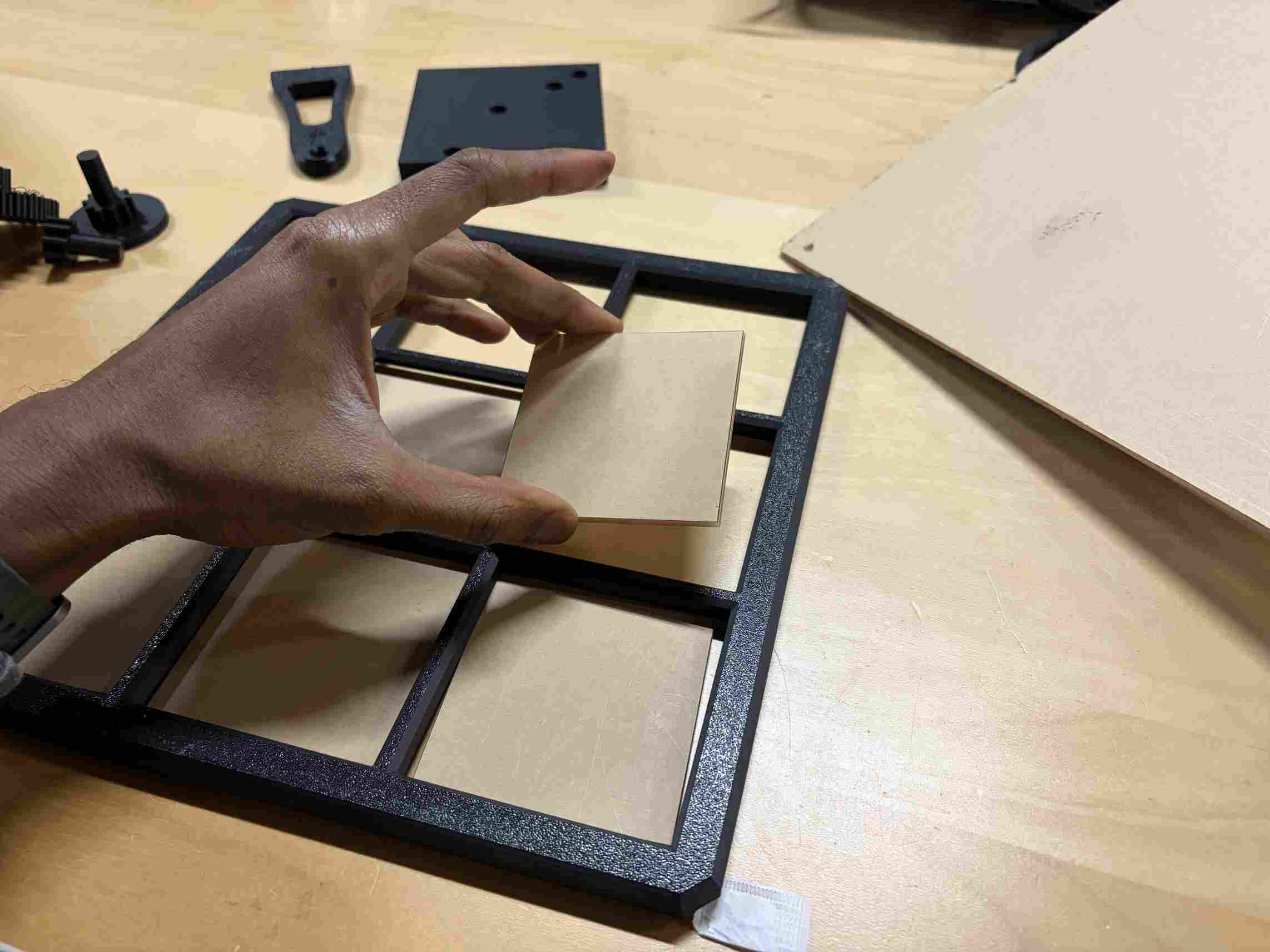
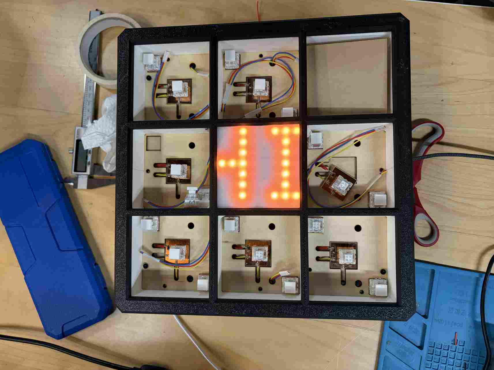
I laser cut the acrylic squares for the tiles and the LED Matrix display.
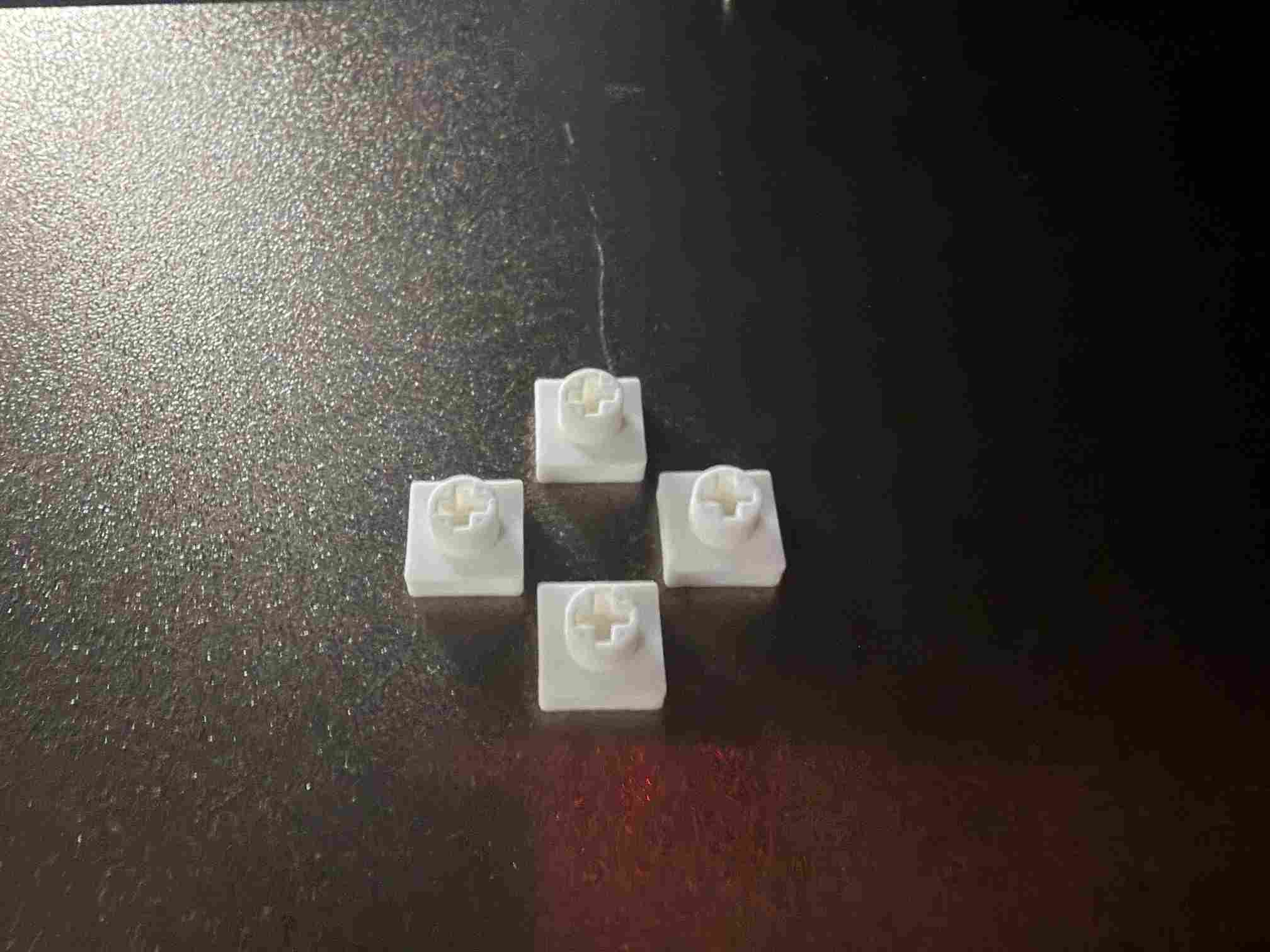
I designed and printed these small caps for the switches to connect them to the LED plates which also support the acrylic tiles.
Click test before gluing.
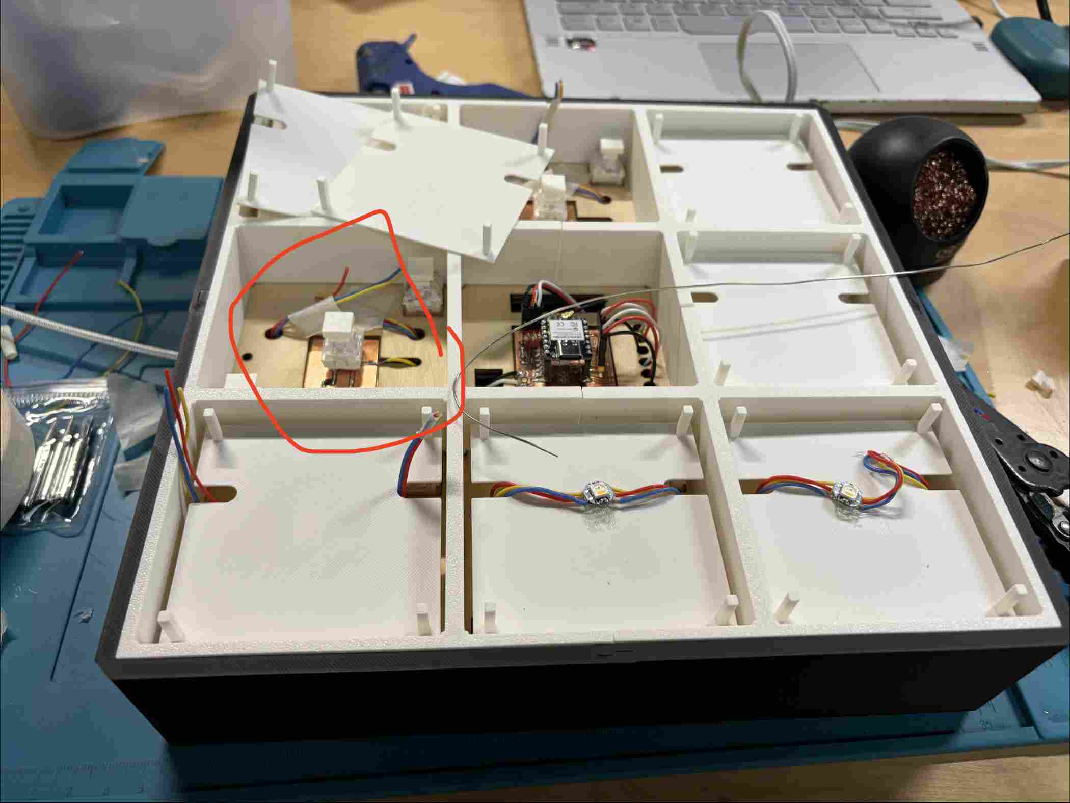
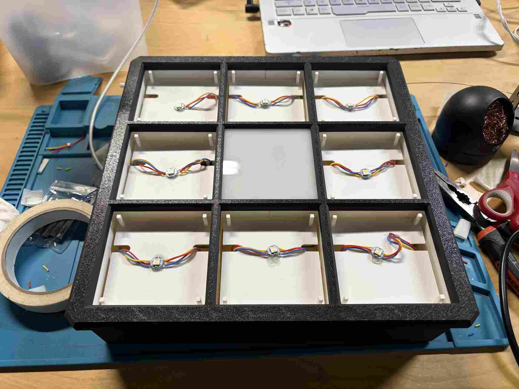
Getting the plates in place, channeling the wires and soldering the LEDs
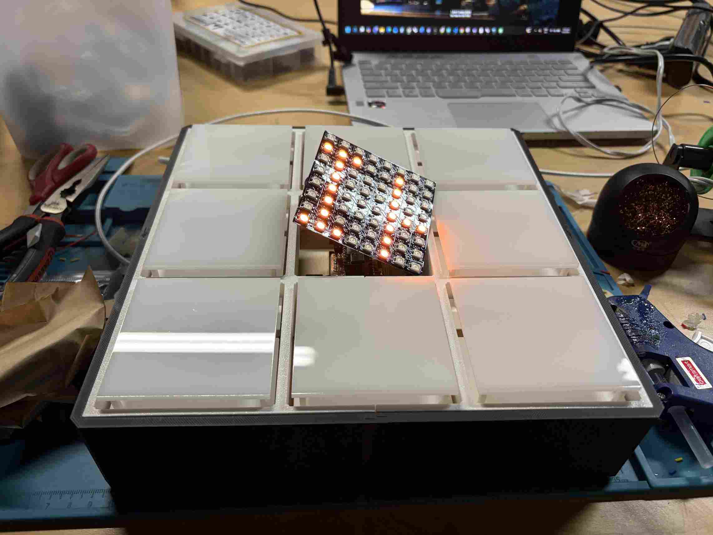
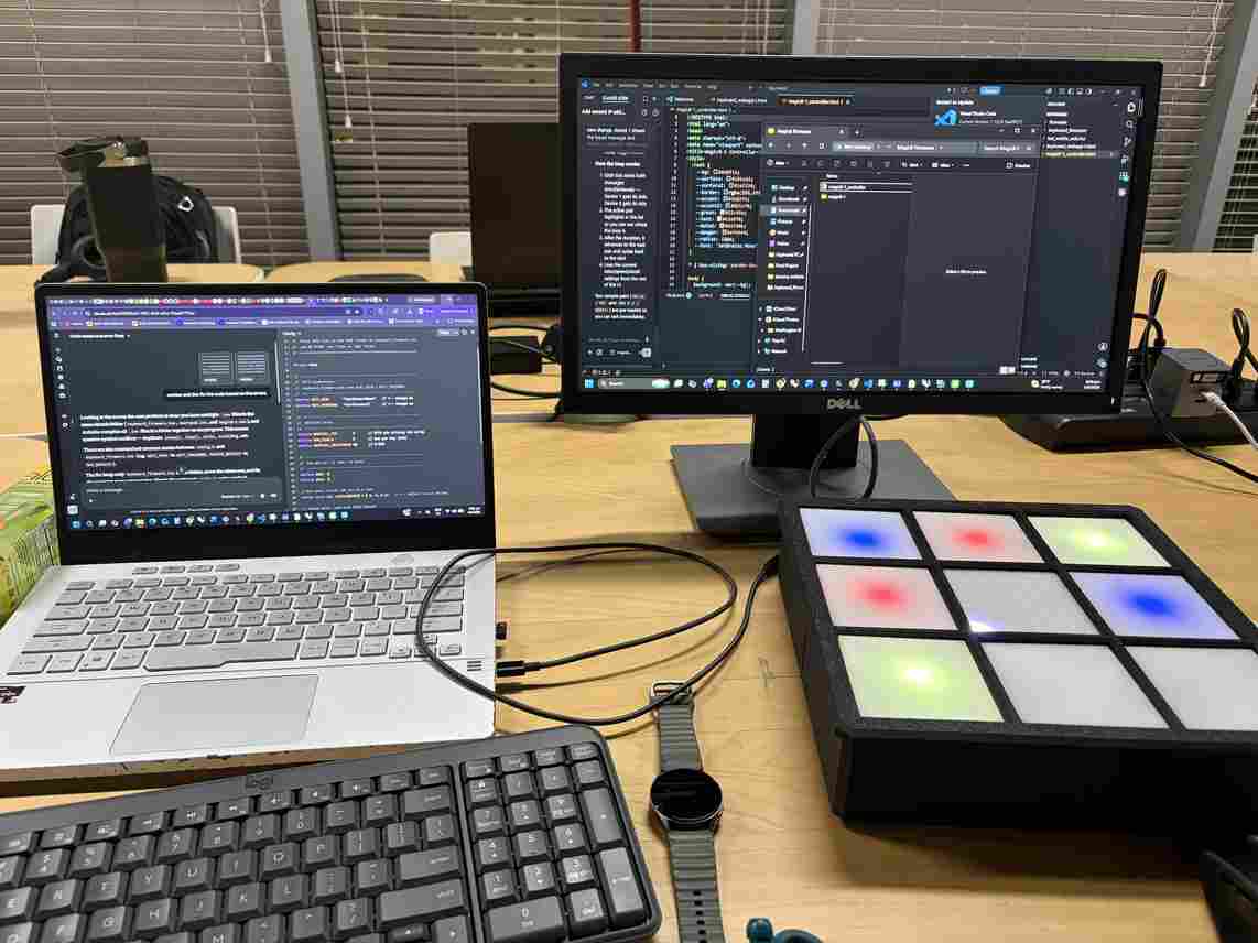
I eventually glued the LED matrix and acrylic to the top frame and put everything together. Next was to troubleshoot the firmware and HTML with Claude's help.
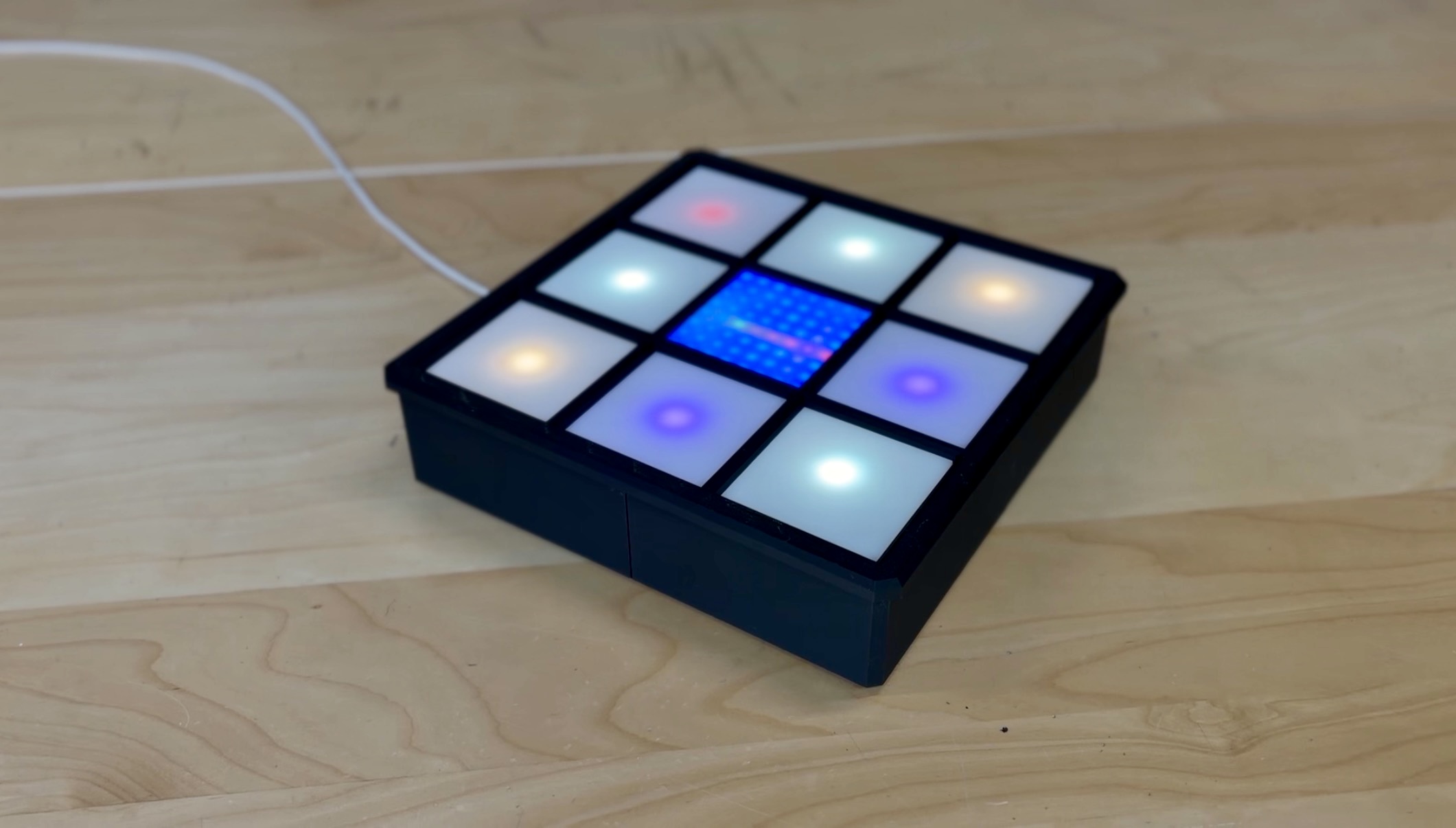
This is the Final Product.
Link to Final Project Page