

3. Computer Controlled Cutting
During Week 3 of computer-controlled cutting, I reviewed the safety guidelines for the laser cutters used at Moonlighter FabLab. The machines we use are manufactured by Full Spectrum, and I am already certified to operate the Full Spectrum laser cutter line.
Week 3 Group AssignmentWeek 3. Computer-Controlled Cutting Group Project
Tasks
-Do your lab’s safety training.
-Characterize your lasercutter’s focus, power, speed, rate, kerf, joint clearance and types.
-Document your work to the group work page and reflect on your individual page what you learned.
Laser Cutter Certification and Safety Certifications
I earned my Laser Cutter Certifications for the Full Specrum P Series Lasers when I started working at Moonlighter FabLab.

Laser Cutter Characterization
Focus
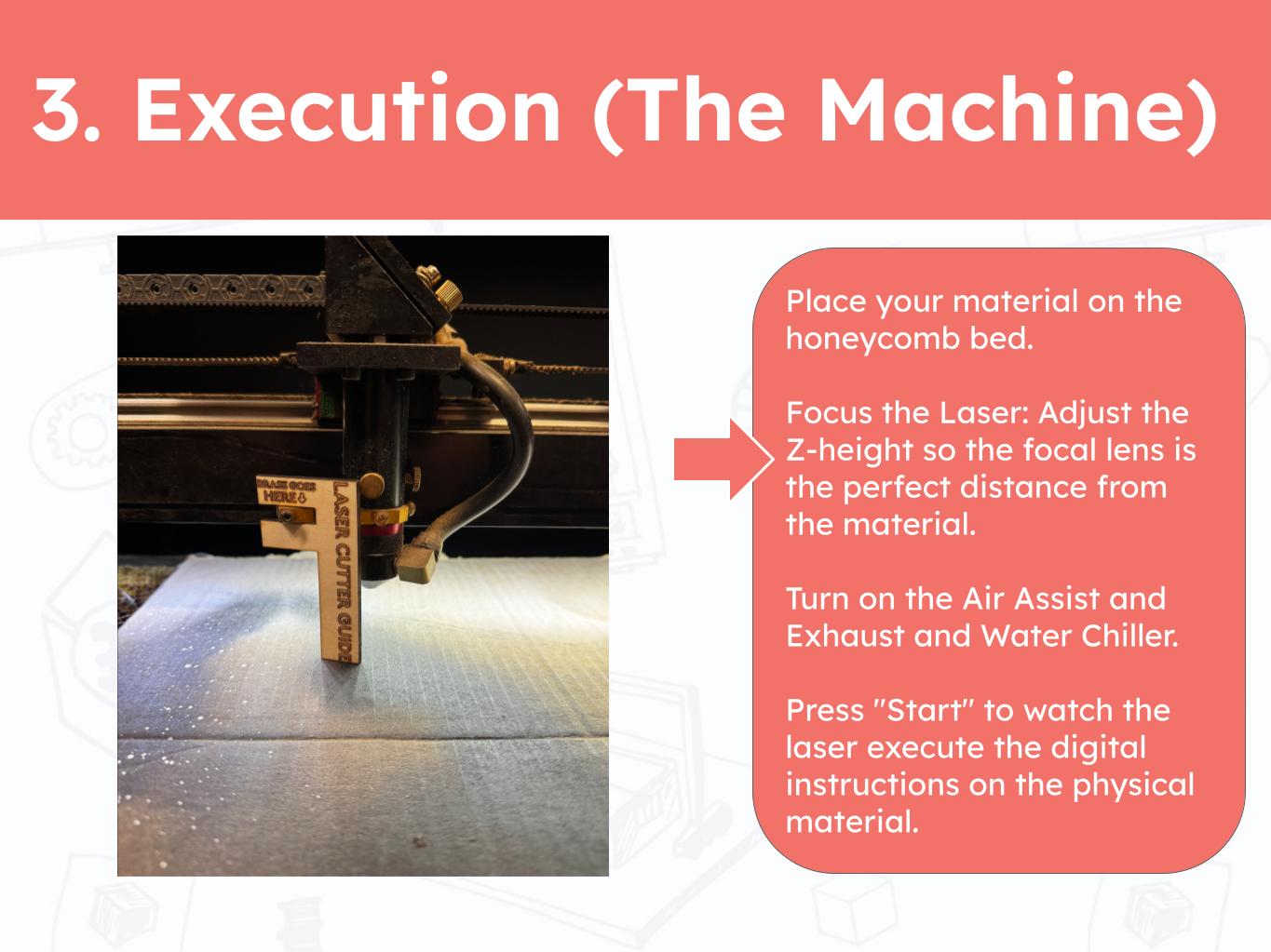
The Laser Cutters at Moonlighter FabLab do not have the auto focus tool which means we are required to manually focus the focus head to the material using a laser cutter guide placed on the brass holder which would have housed the official focussing component. Focusing a laser is very important for the quality of the cut. A we well focused laser can produce sharper cuts with less unwanted burning.
Speed, Power and Current
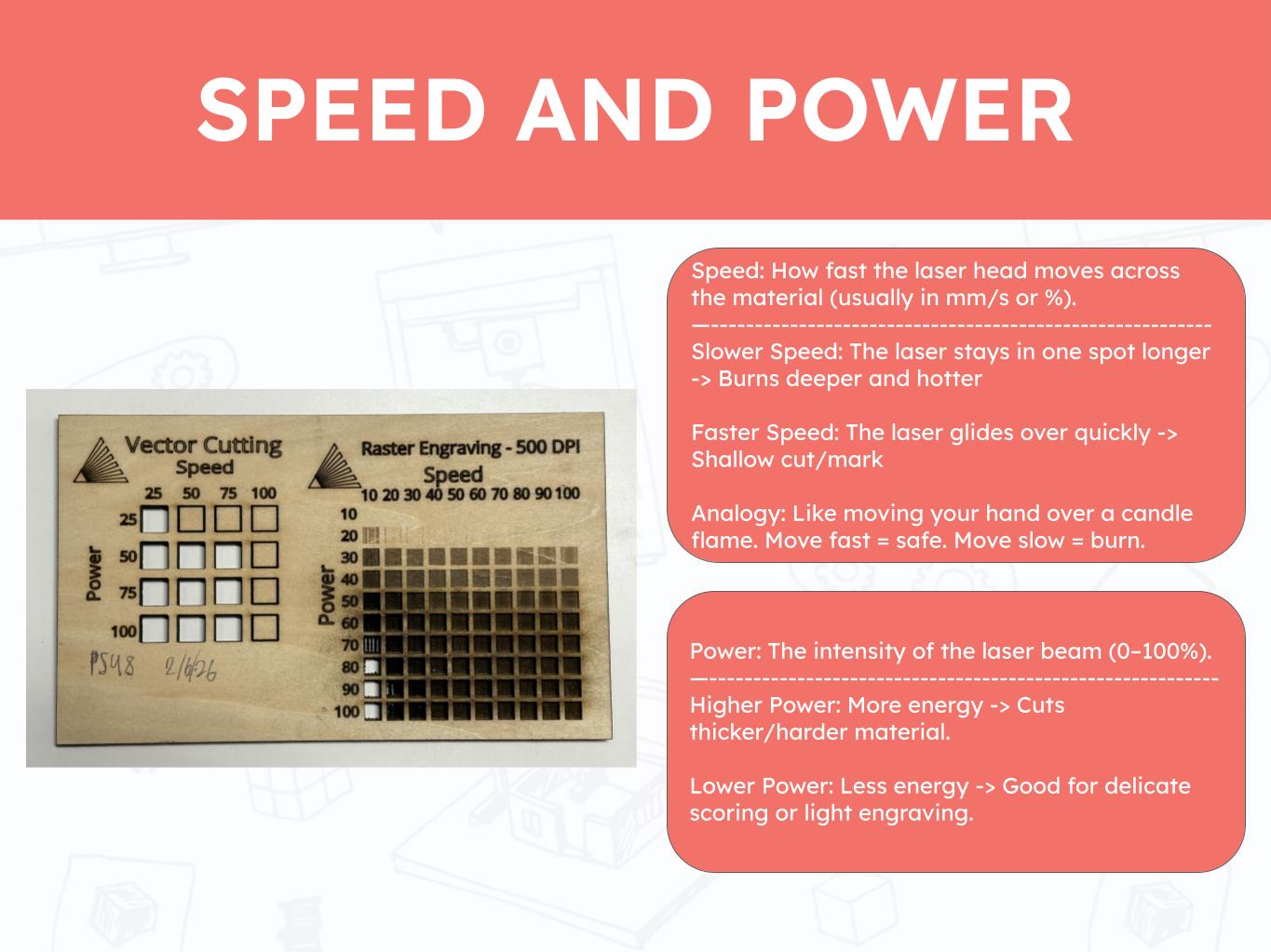
Testing the speed and power is an important step in preparing a laser cut as it can save time and prevent the material from burning. I understand that a 1/8" sheet of bass wood can be cut through with 70 Speed, 70 Power, 100 Current and 1-2 passes.These values may changed depending on the calibration of the machine. An example of an unexpected difference would be when a lower power of 40-60 with 1 pass might cut through. This can meanthat the machine was recalibrated, the leveling was done incorrectly, or that the material was thinner or softer than expected.
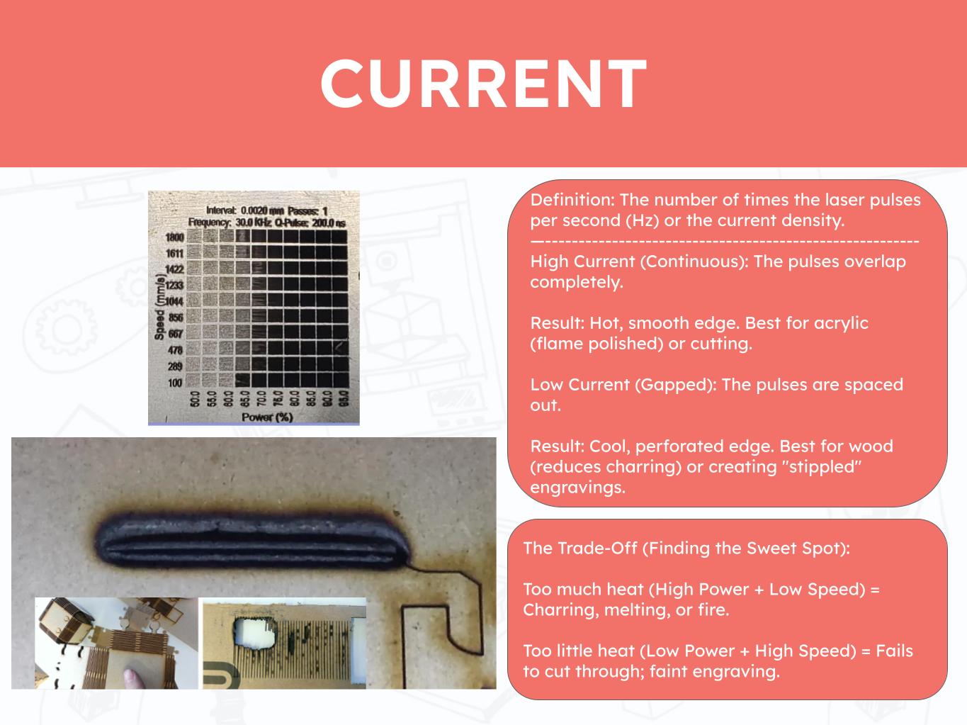
We normally keep the current at 100 to ensure that our cuts have the best chance of going through the material. It is worth reducing the current for engraving operations.
Kerf
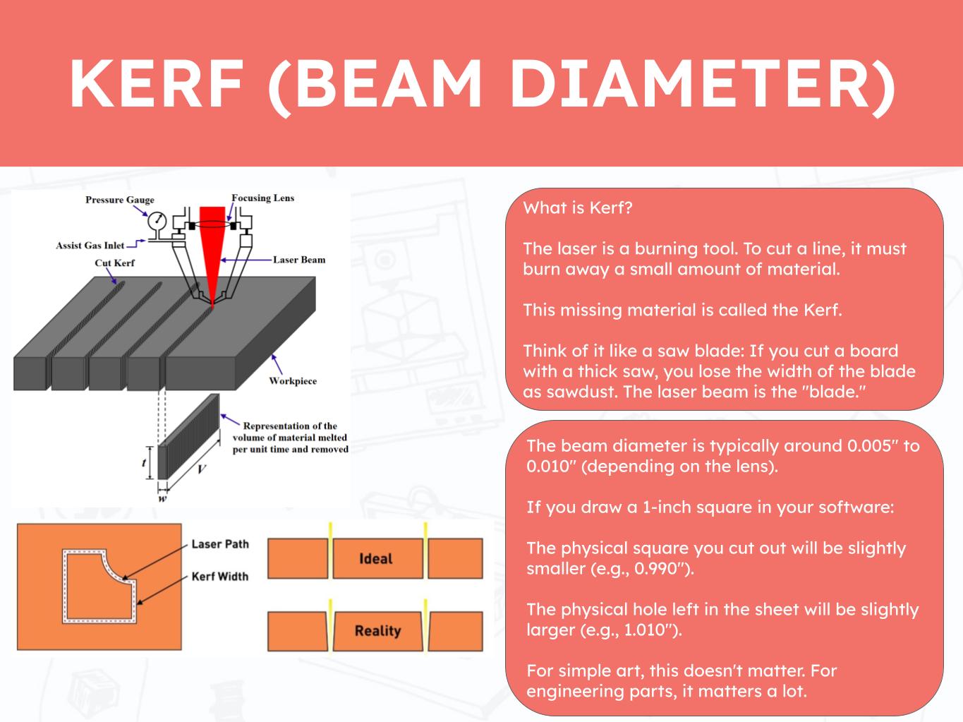
Understanding the kerf of the Moonlighter FabLab Laser Cutter was very helpful in this week's project. I knew that I would need to account for the kerf in som way but this was the first time I learned that there are actual values.
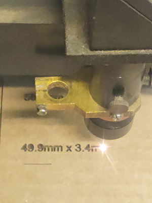
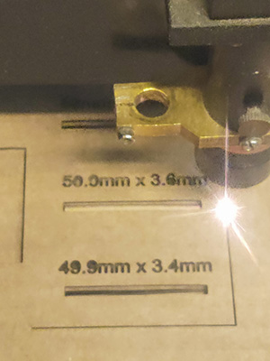
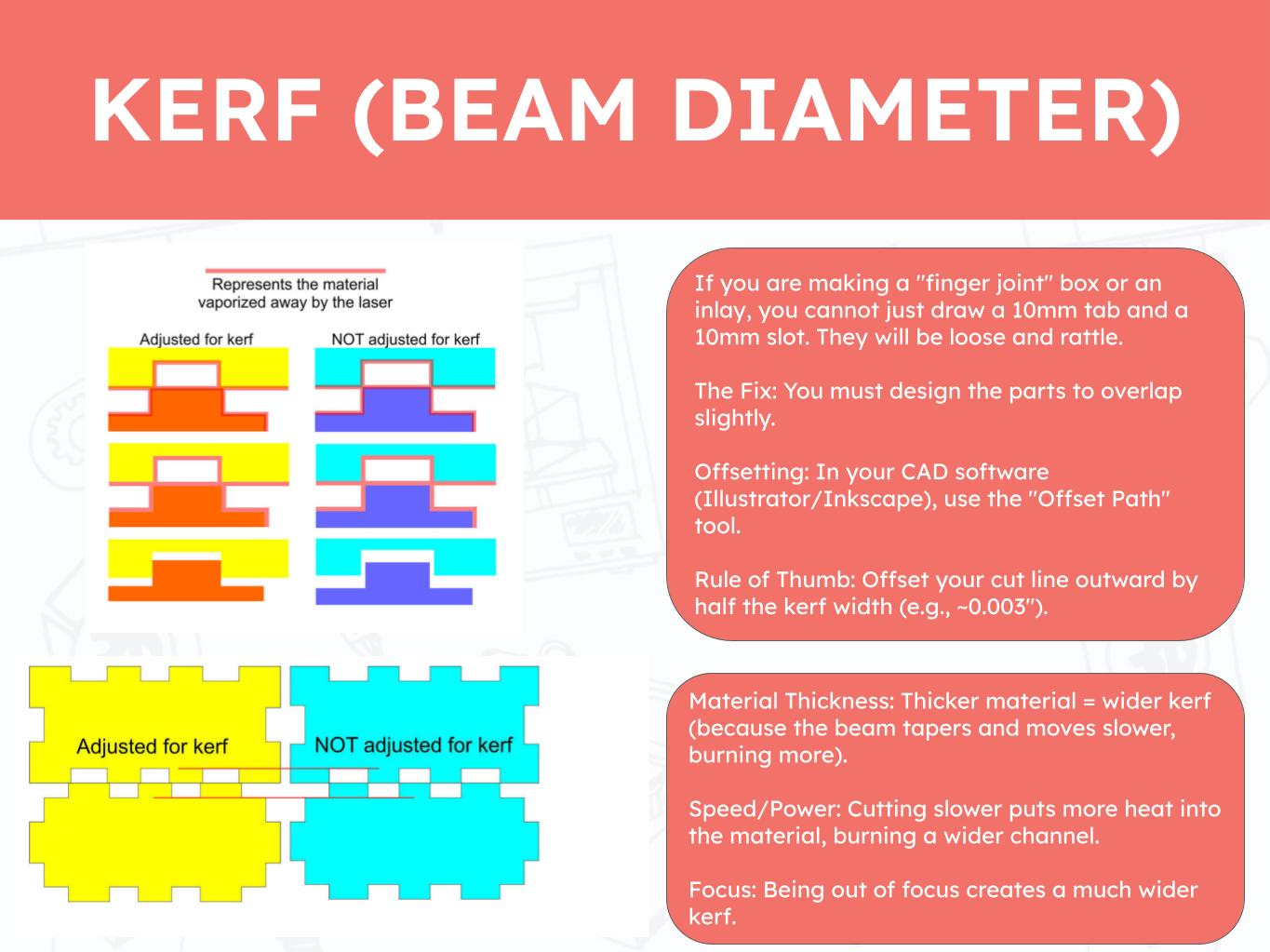
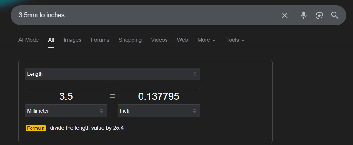
I designed a simple test for my cardboard using my usual method to getting a rough material thickness with a ruler. I made slots ranging from 3.4mm to 3.6mm to see which one would have the correct dimensions for my material and how the Kerf changes the fit.
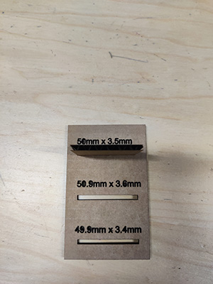
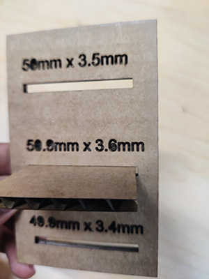
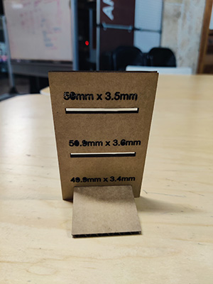
I was able to get the material to fit in all 3 slots. the difference was very subtle differences. My conclusion is that in a difference form factor, the diffences in kerf would be more pronounced.
As I explored the training materials more deeply, I revisited the focusing protocol for the laser’s focus head, which involves using the focusing guide tool attached to the head itself. I also reviewed the key parameters of speed, power, and current.
Speed and power are the primary settings typically adjusted when programming cuts. I was already familiar with the concept that higher speeds reduce the amount of time the laser interacts with the material, while higher power increases the cutting force exerted by the laser.
Current, however, was a newer concept for me. I found it particularly interesting to learn that current influences the difference between producing dotted cuts versus continuous lines.
Vinyl Cutter
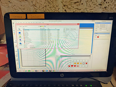
I opened the Sure Cuts Alot software on the vinyl cutter computer and imported the design files to the cut area.
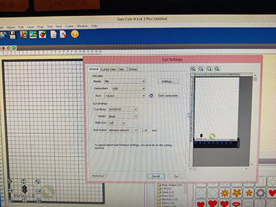
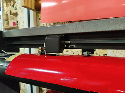
I tried to layout the drawings in a way that it would minimize material wastage. This will take make practice to maximize my layout effectiveness. Onece that step was done, it was time to start cutting. This was a quick cut, apart from the time the vinyl sheet fell through the cutter when it was calibrating. Thankfully the cutter blade had no damages.
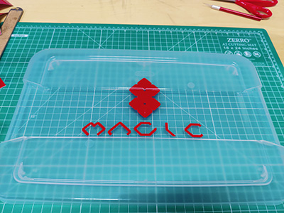
Using transfer paper, I was able to successfully apply my vinyl-cut logo design onto the container lid used for my project.
Laser Cutter Kerf Test
Parametric Push Fit Kit
Using a PCB layout similar to a keyboard, each tile will act as a key clicked with each player move. The cells will be numbered to follow a typical chess board I will need to study keyboard and key assemblies. The general idea is that the key assembly would allow the tile to click smoothly while the RGB LED shines through uninterrupted.
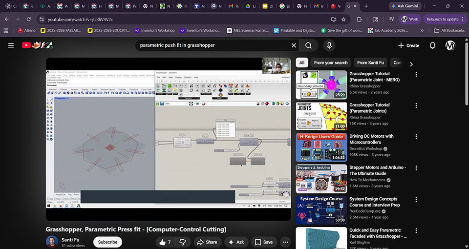 Link to YouTube
 followed the tutorial
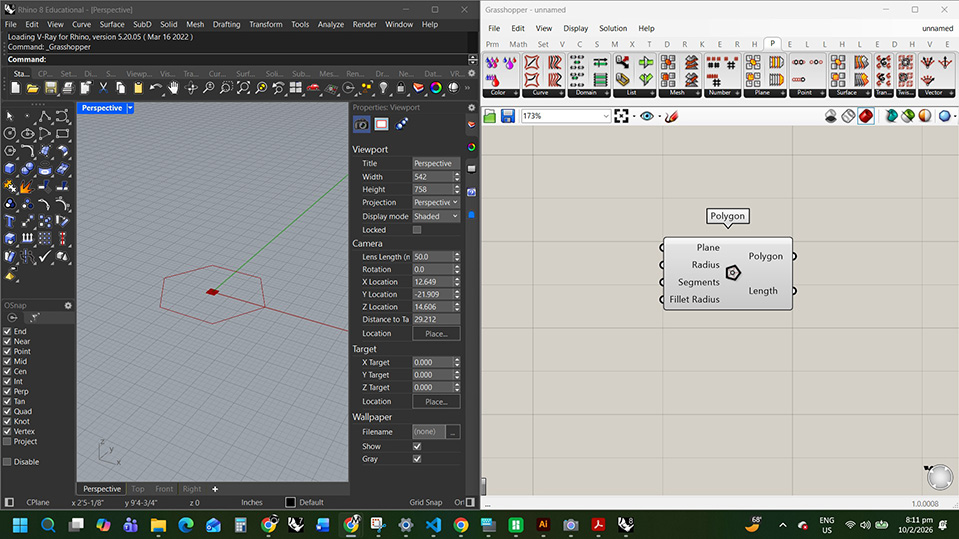
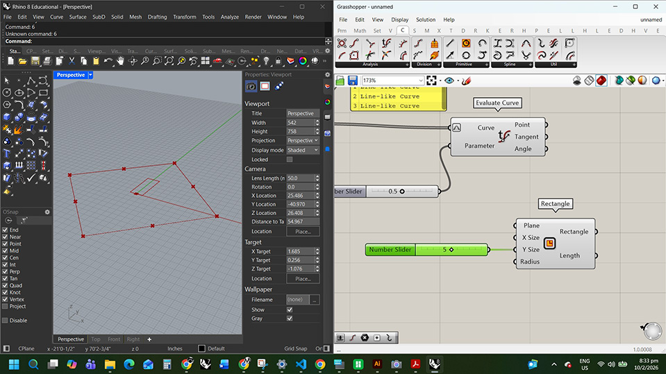
place polygon
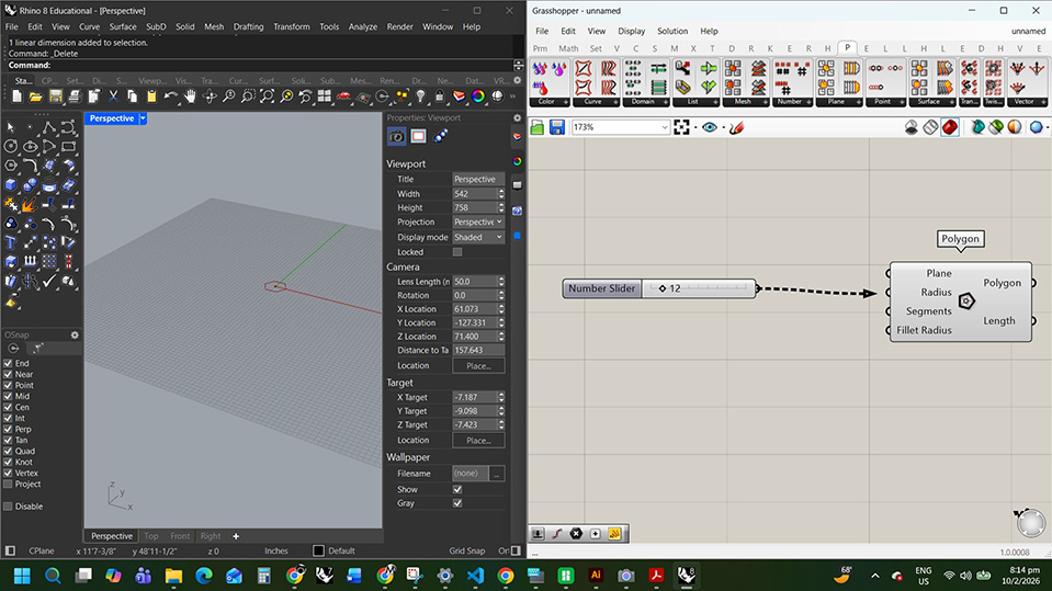
create a 12 in numb slider to radius
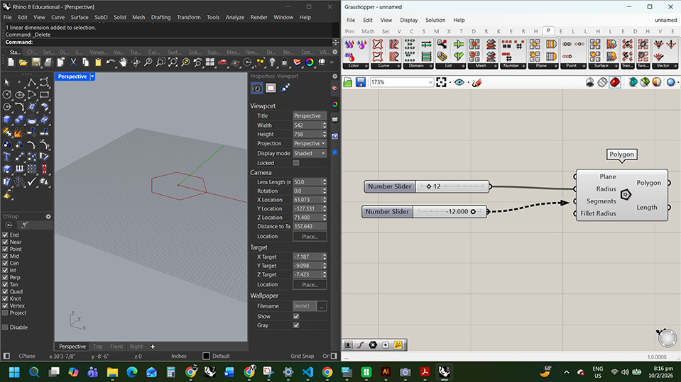
create a 0 to12 numb slider for segments
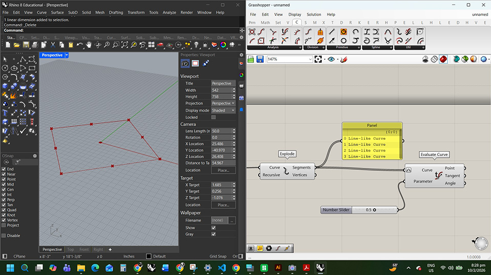
following along with the explode and evaluate curve
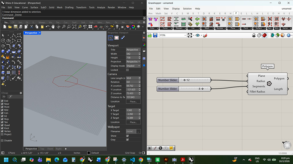
I did it wrong. this is the correct segments
adding a rectangle and a numb slider to change dimensions
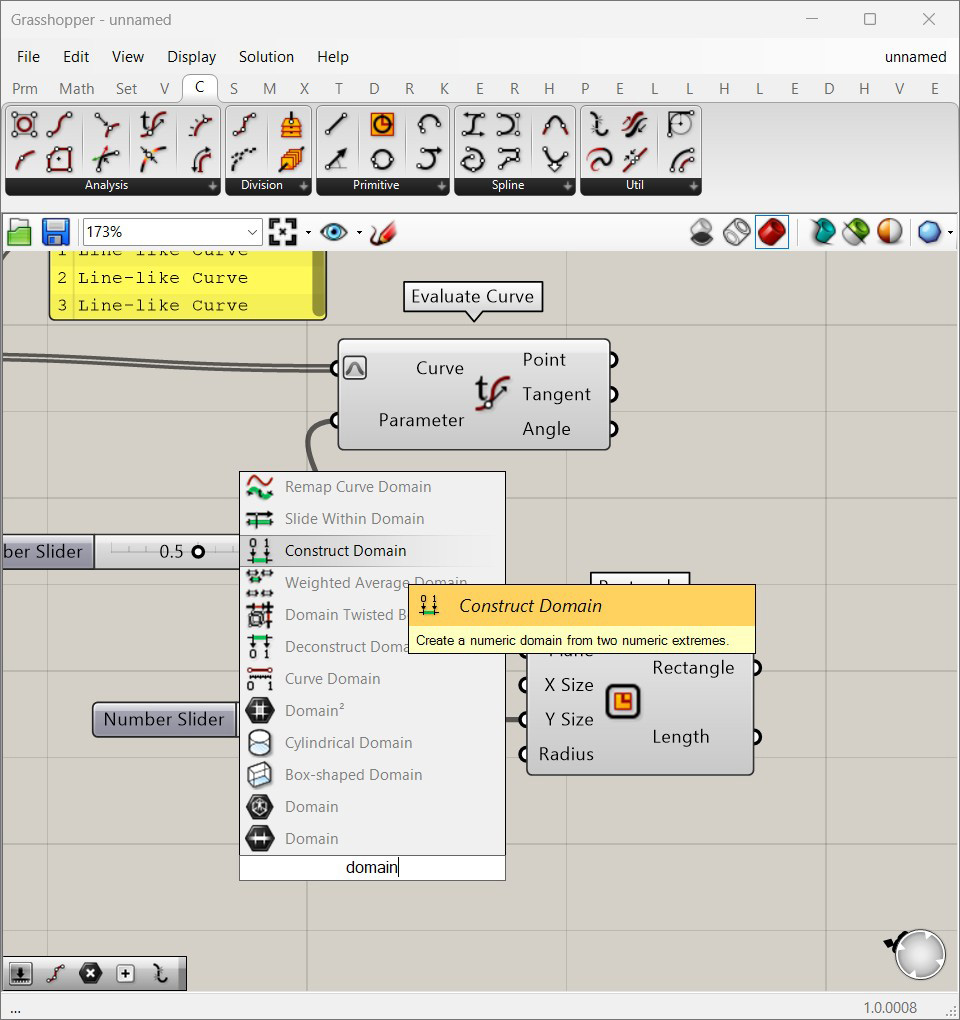
adding a construct domain
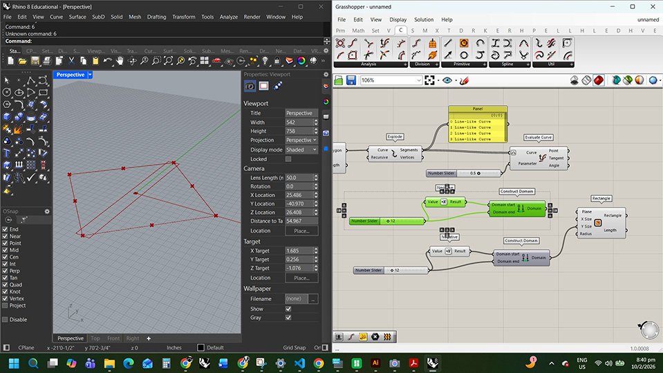
adding negatives so the rectangle scales in 2 directions and duplicating the commands for the x size
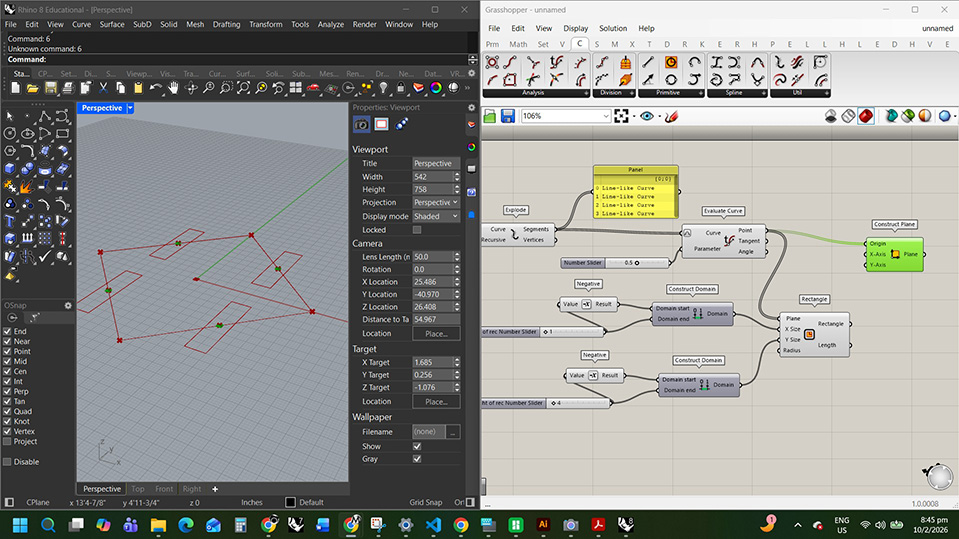
creating the planes
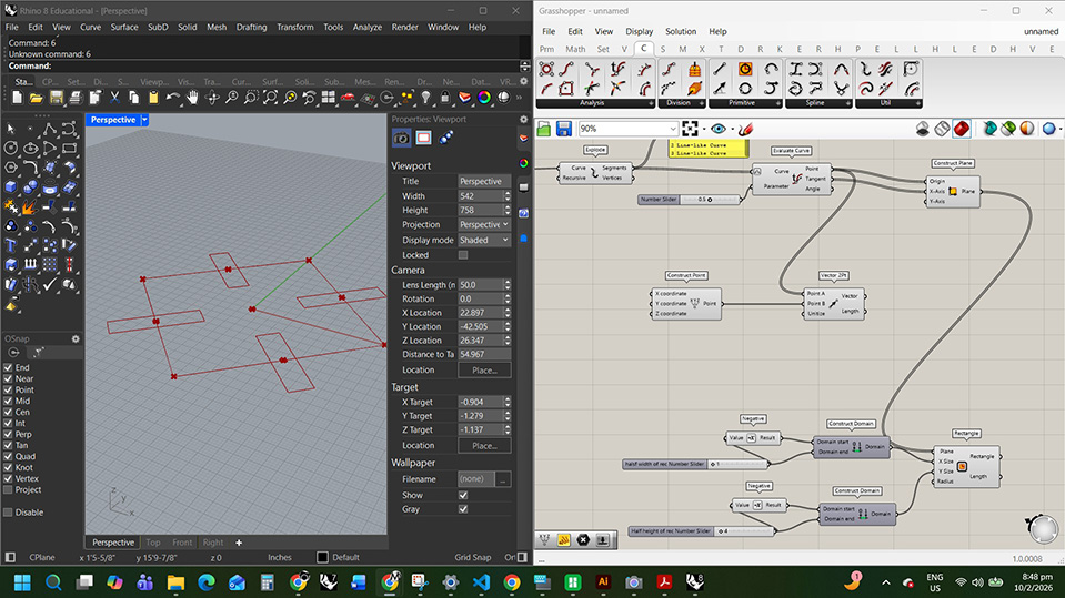
aligning the vectors
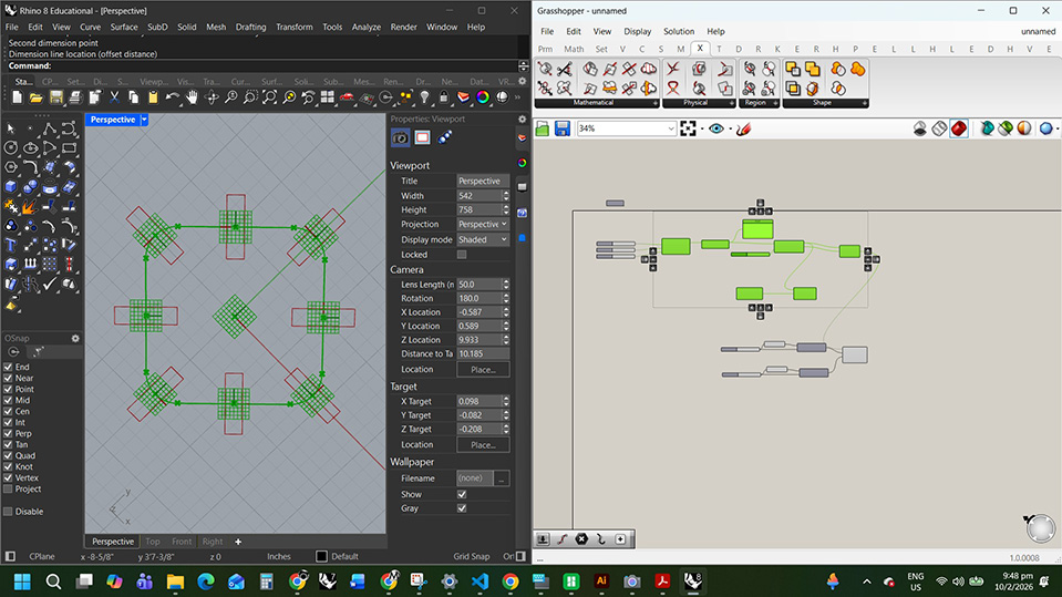
I set the square to the dimensions I want to cut and made the slots the width of my cb
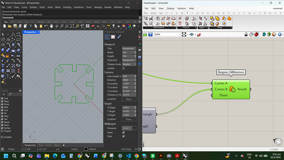
region difference to get the final shape
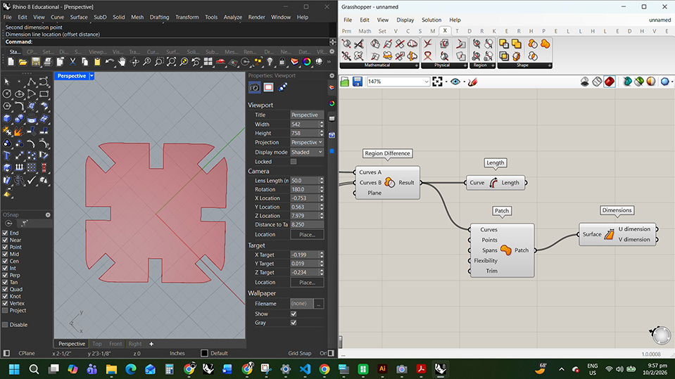
made a surface
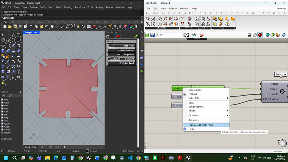
publish to remote panel and make a grasshopper tab in the rhino side panel
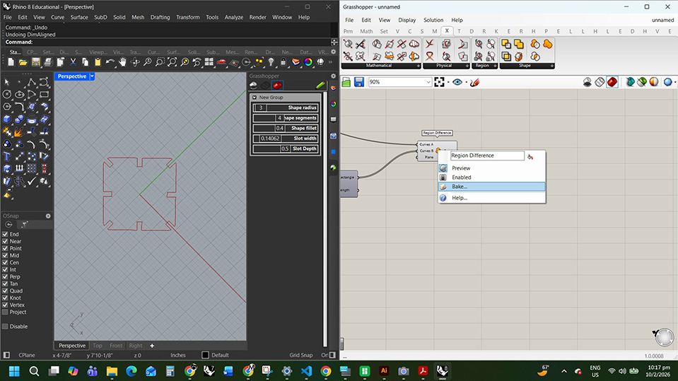
Bake the shape into rhino
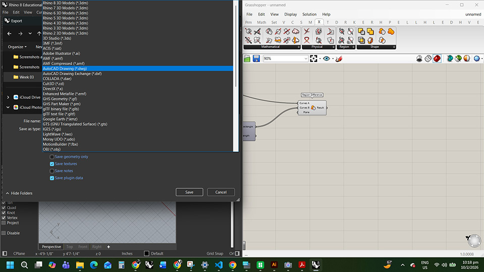
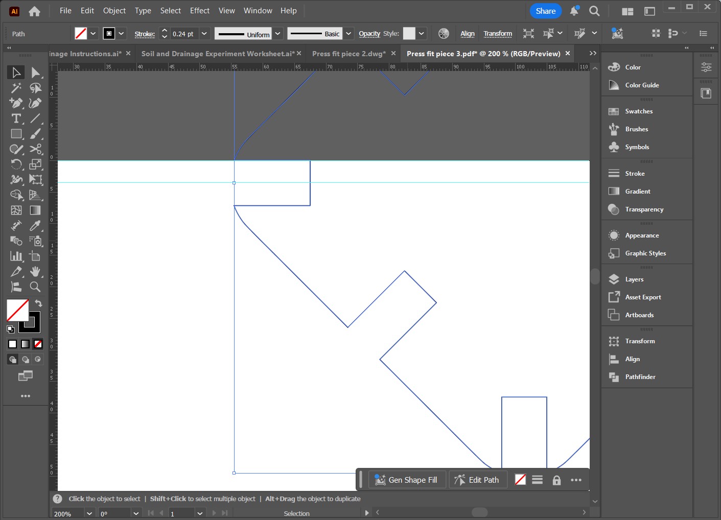
export the selected object as DWG
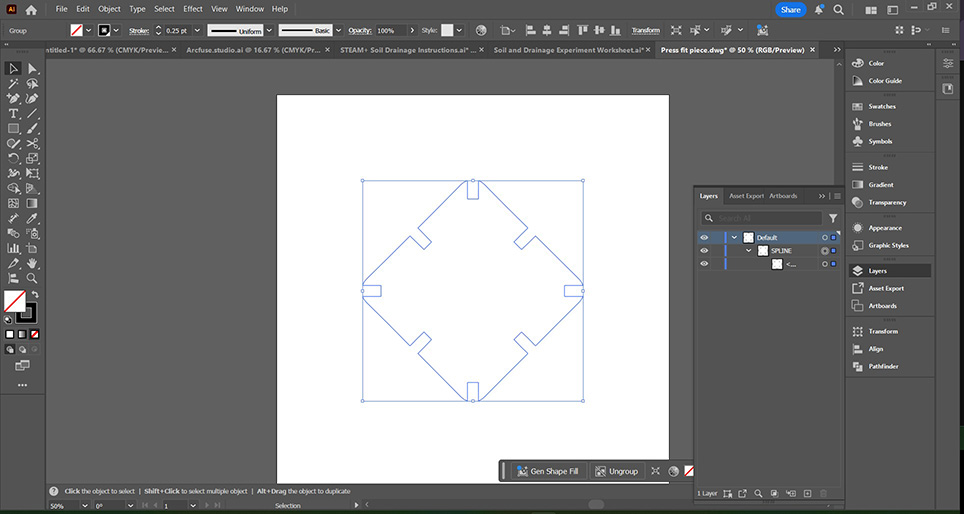
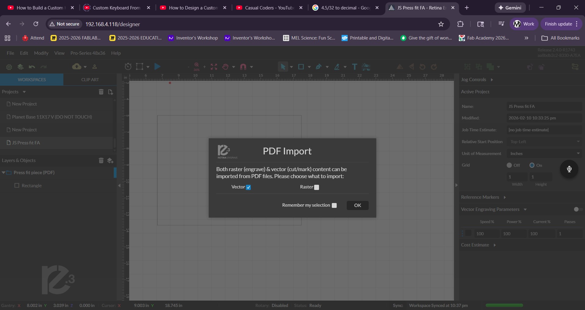
import into illustrator and set stroke to .25
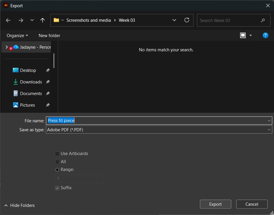
export as pdf
Laser Cutting Push Fit Kit
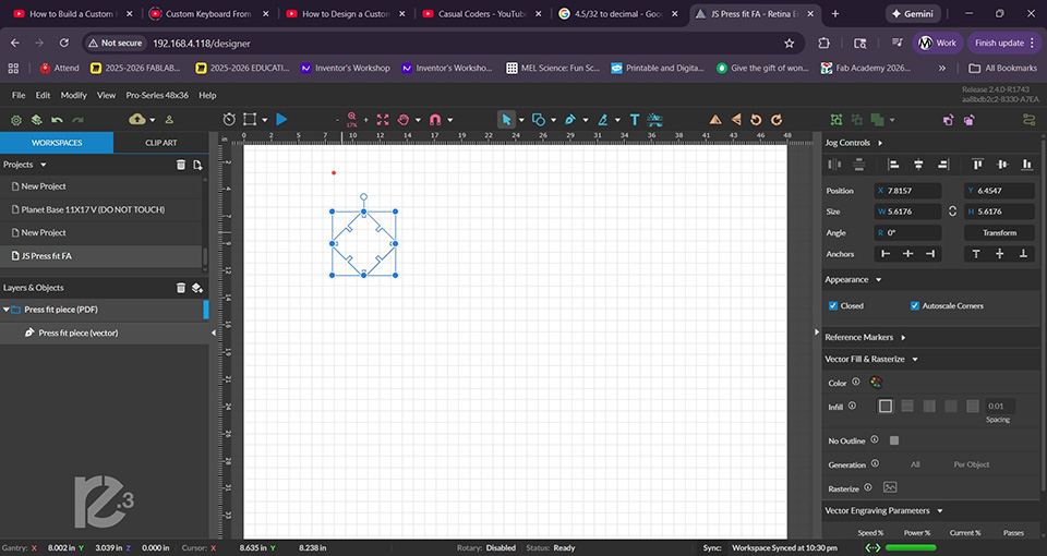
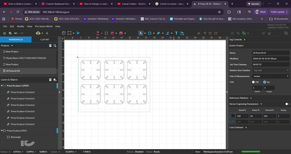
importing the drawing into they laser cutter interface
I want to fit more pieces on my material so I'll make them smaller
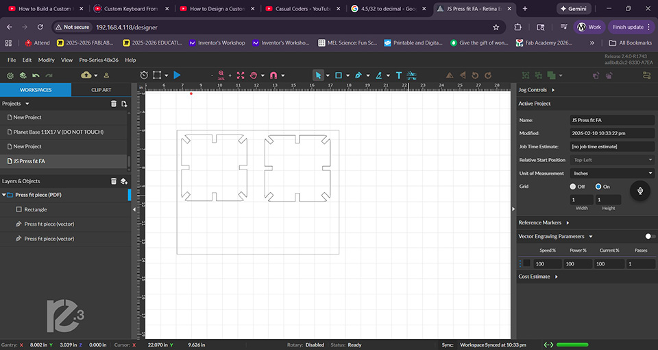
importing the new drawing
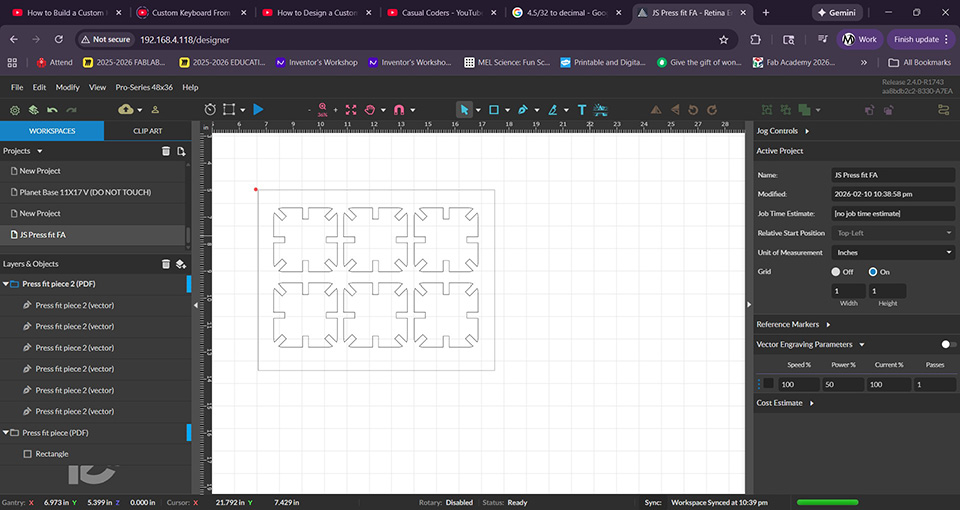
the drawing are ready and I set the speed to 100 power to 50 and 1 pass
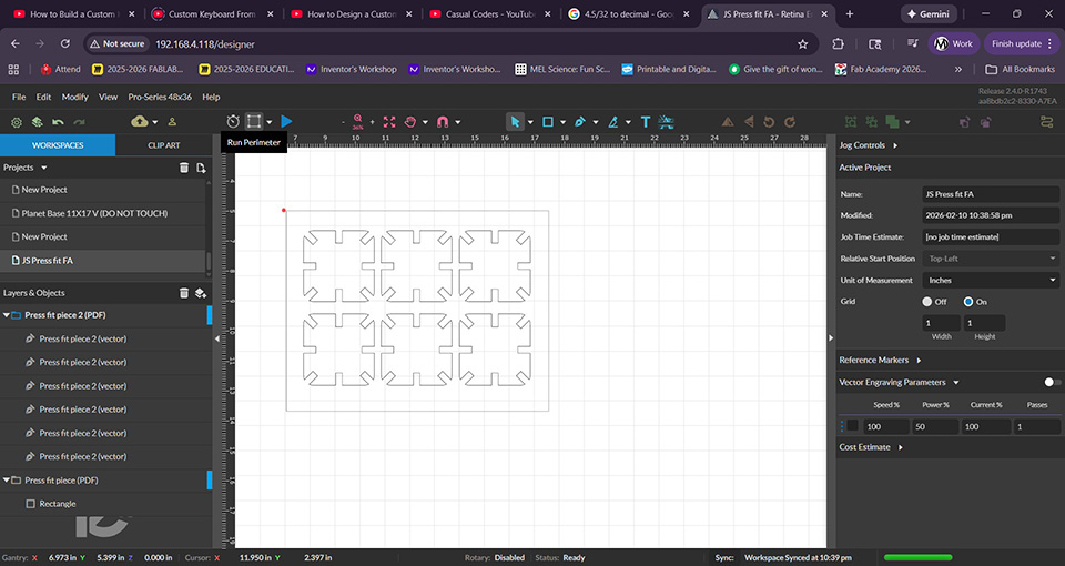
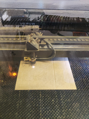
I run perimeter to make sure the material is in the right place
my measurements seem to be ok. the problem must be with the drawing
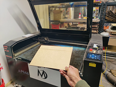
Placing my cardboard
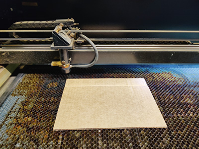
making sure the cardboard is aligned
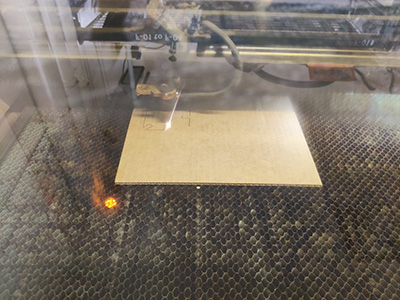
starting the cut
stopped it because the scale was off
slots are way too big
I just remembered that the slot width is a radius. to correct it I need to enter half the desired dimension
I fixed it
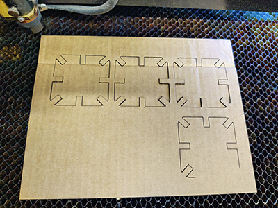
I fixed the size issue and sent it to cut
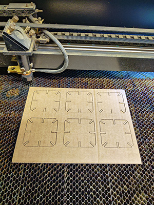
the corrected design cut perfectly
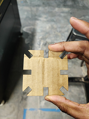
I felt very proud of the correction and even more excited to assemble the parts.
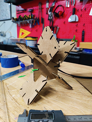
the assebled parts
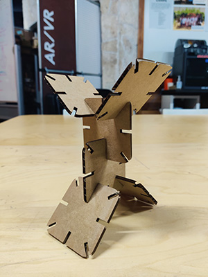
the assebled parts