I) Group Assignment
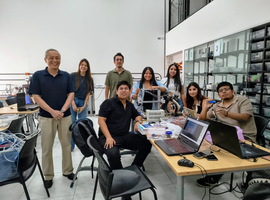
During the development of the group work, I connected virtually since I cannot travel to the city of Lima due to the distance from where I am located, so my classmate Jianfranco explained in detail what was done in the group work that was carried out at the FAB LAB of Universidad del Pacífico.
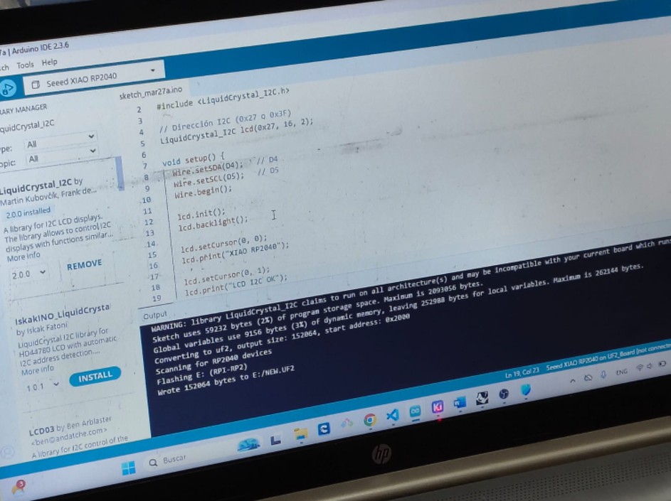
Library installation for our devices
For the proper operation of the sensors, it was necessary to install some libraries in Arduino IDE. These libraries make communication between the microcontroller and the sensors easier, simplifying data reading and processing. In this group work, I learned how to search for the libraries for each of the output devices we used and then verified that the compilation was correct. For this exercise, we used Adrian Torres's FABXIAO board and, as the first device, an LCD screen. In the case of the LCD screen with the I2C module, the following library was used: LiquidCrystal_I2C, which allows the LCD screen to be controlled through I2C communication, reducing the number of required pins and facilitating data display.
Img 1
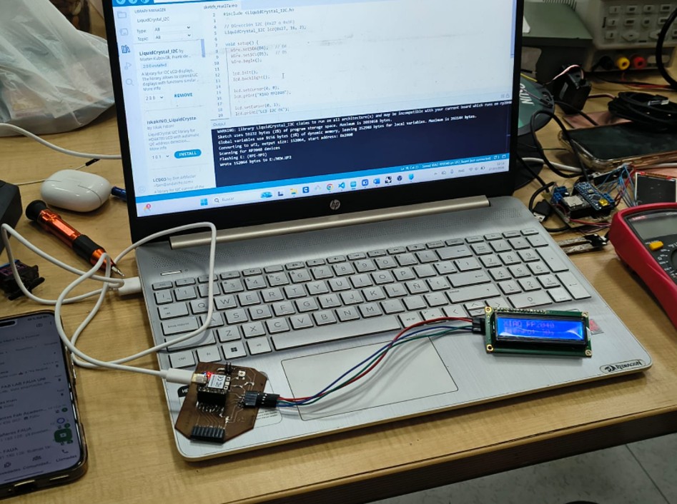
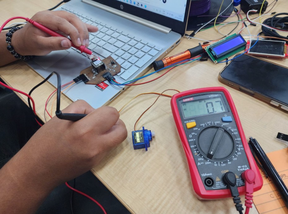
Checking the power consumption of the devices
For this group work, we first created the code to program the LCD screen and the servo motor. Then, we connected the devices to the board and measured the power consumption with a multimeter. We measured consumption at rest and during operation of the devices, and later verified it using the basic power formula. We also confirmed that the servo motor consumes more energy than the LCD screen.
Img 2
Img 3
Conclusion
In conclusion, the multimeter is a very useful tool for measuring the power consumption of devices. We also confirmed that the servo motor consumes more energy than the LCD screen because the servo motor has an internal motor that requires more energy than the LCD screen. In addition, we verified that the power consumption at rest is lower than the power consumption during device operation, since they require more energy while working.
II) Individual Assignment
For the individual work, I worked on the board that I produced in week 8, more information here: Week 8, and with the temperature and TDS sensors that I used in week 9, more information here: Week 9.
I added an output device to my microcontroller board. In this case, I used an LCD screen to display Temperature and TDS data, which will be very useful for my final project.
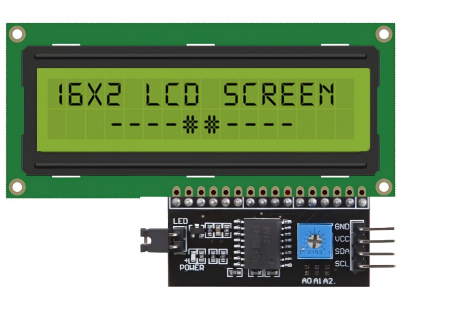
2.1. 16x2 LCD screen with I2C module
During the development of the project, a 16x2 LCD screen with an I2C interface was used, which made it possible to visualize the values obtained from the temperature and TDS sensors in real time. This type of screen is widely used in electronic projects due to its ease of use, low power consumption, and simple connection.
Img 4
2.1.1. Main characteristics
- 16-column x 2-row alphanumeric display
- I2C interface, which reduces the number of required pins
- Controller based on the HD44780 chip
- LED backlight
- Contrast adjustment through a potentiometer
- Compatible with Arduino, ESP32, and other microcontrollers
Technical specifications
- Operating voltage: 5V
- Current consumption: ~20 mA
- Communication: I2C (SDA and SCL)
- Common I2C address: 0x27 (may vary)
- Resolution: 16x2 characters
- Operating temperature: 0°C to 50°C
2.1.2. Operation
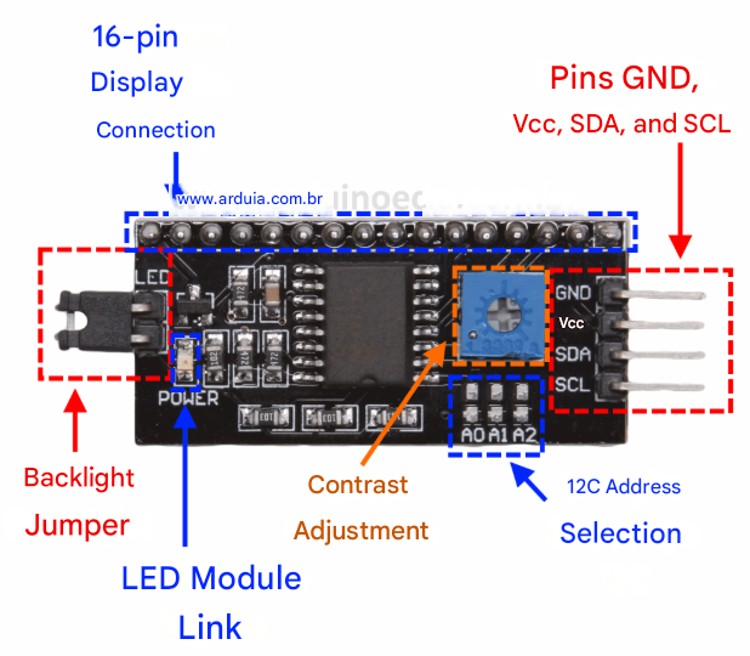
The LCD screen works through a character matrix controlled by the HD44780 chip. In this case, the I2C module acts as an intermediary, allowing the microcontroller to send data using only two pins (SDA and SCL). The microcontroller sends information through the I2C protocol, which is interpreted by the module and converted into signals that the screen can understand in order to display text. The screen used includes an I2C adapter module on the back, also known as an I2C backpack. This module is responsible for simplifying the connection.
Img 5
Module components:
- PCF8574 chip: converts I2C signals to parallel communication
- Potentiometer: allows screen contrast adjustment
- Indicator LED: shows that the module is powered
- Connection pins (4): VCC, GND, SDA, SCL
Thanks to this adapter, the screen only needs 4 connections instead of the 6 to 12 pins required by a conventional LCD. This makes assembly easier, reduces errors, and improves circuit organization. LCD without I2C: requires multiple digital pins and more complex wiring. LCD with I2C: uses only 4 pins and is easier to program.
Img 6
2.1.3. Applications
- Automation projects
- User interfaces
- Real-time data visualization
2.1.4. Advantages
- Easy to use and program
- Reduces the number of pins
- Low power consumption
- Affordable
- Good visibility
2.1.5. Disadvantages
- It only displays text
- Limited resolution
- Requires contrast adjustment
- The I2C address may vary
- Not suitable for complex graphics
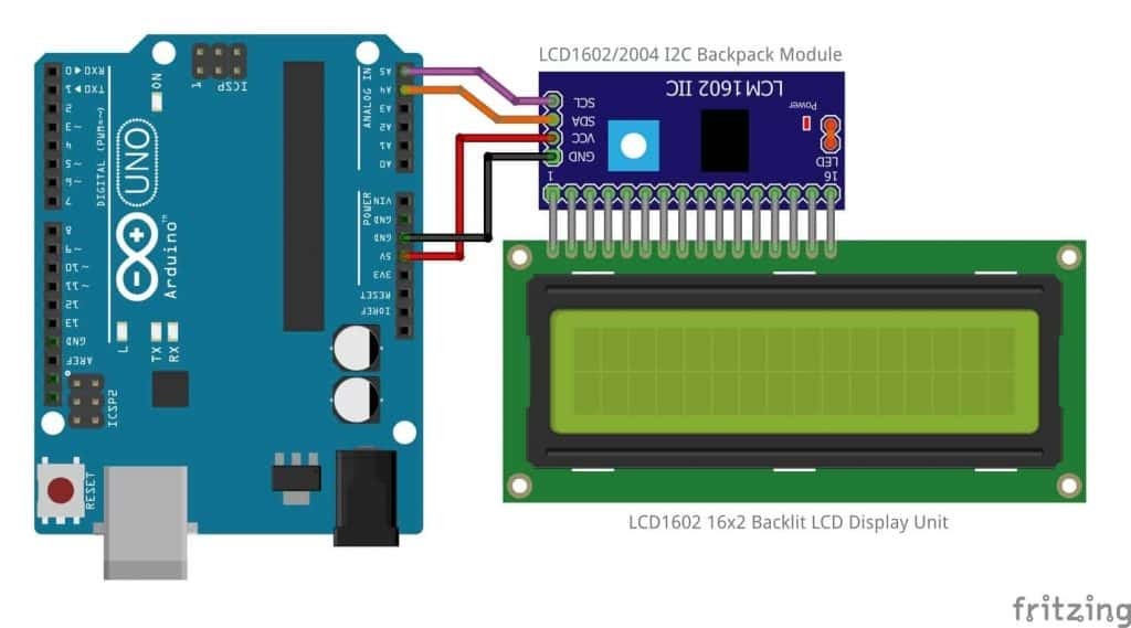
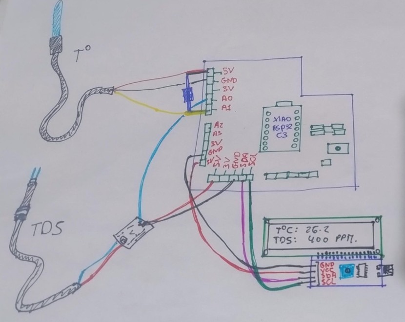
2.2. Connection of the output device and what I learned
I made the physical connection of the LCD screen to my board. This was not very difficult because the connection was direct: GNG-GND, V5V-V5V, SDA-SDA, and SCL-SCL, so my connections looked like this:
Img 7
Since I had to reinstall Arduino IDE because it could not read the serial monitor, I had to download the libraries for the input and output devices again.
Libraries used for sensors
For the proper operation of the sensors used in this project, it was necessary to install some libraries in Arduino IDE. These libraries help facilitate communication between the microcontroller and the sensors, simplifying data reading and processing. To do this, I saved my libraries on a USB drive and then downloaded them into the Arduino IDE folder.
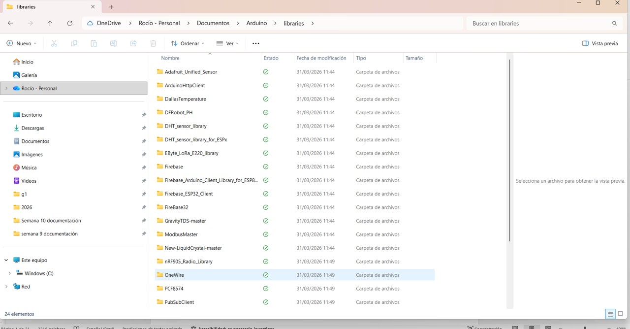
Img 8
In the case of the DS18B20 temperature sensor, the following libraries were used: OneWire, which enables communication through the OneWire protocol used by this sensor; and DallasTemperature, which makes temperature reading easier because it works on top of the OneWire library and simplifies obtaining data in degrees Celsius.
For the TDS (Total Dissolved Solids) sensor, a specific library is generally not mandatory, since this sensor provides an analog signal. However, code based on conversion formulas can be used to obtain values in ppm. In some cases, a specific manufacturer library (such as DFRobot) can also be used to improve accuracy and facilitate calibration.
In the case of the LCD screen with the I2C module, the following was used: LiquidCrystal_I2C, which allows the LCD screen to be controlled through I2C communication, reducing the number of required pins and facilitating data display.
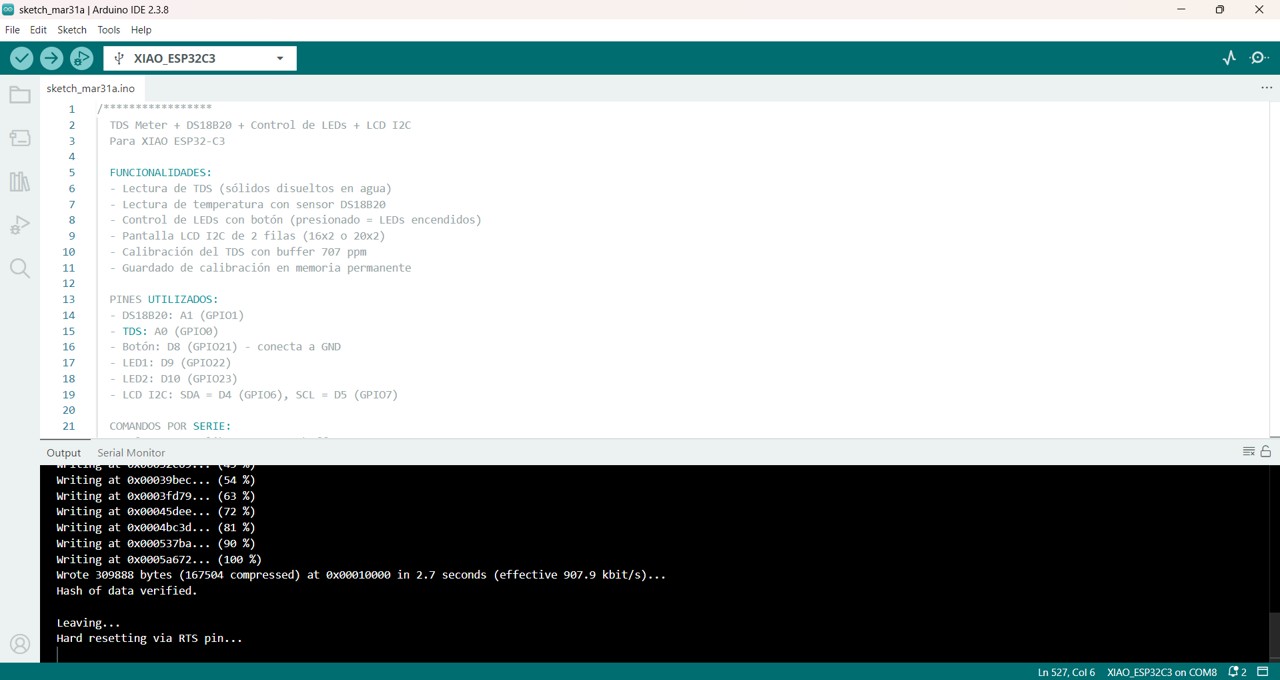
Then I was able to upload the code. For this, I got help from ChatGPT and DeepSeek. I sent them my circuit, my input and output devices, and the code that worked in week 9, and this was the code that later had to be updated according to the libraries.
/*****************
  TDS Meter + DS18B20 + LED Control + LCD I2C
  For XIAO ESP32-C3

  FEATURES:
  - TDS reading (total dissolved solids in water)
  - Temperature reading with DS18B20 sensor
  - LED control with button (pressed = LEDs on)
  - 2-row I2C LCD screen (16x2 or 20x2)
  - TDS calibration with 707 ppm buffer
  - Calibration storage in permanent memory

  USED PINS:
  - DS18B20: A1 (GPIO1)
  - TDS: A0 (GPIO0)
  - Button: D8 (GPIO21) - connected to GND
  - LED1: D9 (GPIO22)
  - LED2: D10 (GPIO23)
  - LCD I2C: SDA = D4 (GPIO6), SCL = D5 (GPIO7)

  SERIAL COMMANDS:
  - cal:707  : Calibrate TDS with 707 ppm buffer
  - reset    : Restore calibration to default value
  - show     : Show current configuration
  - temp     : Read temperature manually
******************/

#include <OneWire.h>
#include <DallasTemperature.h>
#include <Preferences.h>
#include <Wire.h>
#include <LiquidCrystal_I2C.h>

#define DS18B20_PIN A1
#define TDS_PIN A0

const int BOTON_PIN = 8;
const int LED1_PIN = 9;
const int LED2_PIN = 10;

#define LCD_ADDRESS 0x27
#define LCD_COLUMNS 16
#define LCD_ROWS 2

LiquidCrystal_I2C lcd(LCD_ADDRESS, 2, 1, 0, 4, 5, 6, 7, 3, POSITIVE);
#define GRADOS 223

OneWire oneWire(DS18B20_PIN);
DallasTemperature ds18b20(&oneWire);
Preferences preferences;

float kValue = 1.0;
float temperature = 25;
float tdsValue = 0;
float voltage = 0;
int adcValue = 0;

bool lastButtonState = HIGH;
unsigned long lastDebounceTime = 0;
const unsigned long debounceDelay = 50;

unsigned long lastReadTime = 0;
const unsigned long readInterval = 2000;
unsigned long lastLcdUpdate = 0;
const unsigned long lcdInterval = 1000;

void setup() {
  Serial.begin(115200);
  delay(1000);

  inicializarLEDs();
  inicializarBoton();
  inicializarLCD();
  inicializarTDS();
  inicializarDS18B20();
  inicializarADC();

  mostrarInfoInicial();
  mostrarComandos();
}

void inicializarLEDs() {
  pinMode(LED1_PIN, OUTPUT);
  pinMode(LED2_PIN, OUTPUT);
  digitalWrite(LED1_PIN, LOW);
  digitalWrite(LED2_PIN, LOW);
}

void inicializarBoton() {
  pinMode(BOTON_PIN, INPUT_PULLUP);
}

void inicializarLCD() {
  Serial.println("Initializing LCD...");
  Wire.begin(6, 7);
  lcd.begin(LCD_COLUMNS, LCD_ROWS);
  lcd.backlight();
  lcd.clear();

  lcd.setCursor(0, 0);
  lcd.print("  TDS METER  ");
  lcd.setCursor(0, 1);
  lcd.print("  Starting...");

  Serial.println("LCD initialized correctly");
  delay(2000);
  lcd.clear();
}

void inicializarTDS() {
  preferences.begin("tds", false);
  kValue = preferences.getFloat("kvalue", 1.0);
  preferences.end();

  if (kValue < 0.1 || kValue > 10) {
    kValue = 1.0;
    Serial.println("Using default K factor: 1.0");
  } else {
    Serial.print("Loaded K factor: ");
    Serial.println(kValue, 4);
  }
}

void inicializarDS18B20() {
  ds18b20.begin();
}

void inicializarADC() {
  analogReadResolution(12);
}

void leerTemperatura() {
  ds18b20.requestTemperatures();
  float temp = ds18b20.getTempCByIndex(0);

  if (temp != DEVICE_DISCONNECTED_C && !isnan(temp) && temp > -50 && temp < 125) {
    temperature = temp;
  }
}

void leerTDS() {
  long sumADC = 0;

  for (int i = 0; i < 10; i++) {
    sumADC += analogRead(TDS_PIN);
    delay(5);
  }

  adcValue = sumADC / 10;
  voltage = adcValue * (2.5 / 4095.0);
  calcularTDS();
}

void calcularTDS() {
  if (voltage >= 0.01 && voltage <= 2.4) {
    float v = voltage;
    float v3 = v * v * v;
    float v2 = v * v;

    float tdsRaw = (133.42 * v3 - 255.86 * v2 + 857.39 * v) * kValue;
    float tempComp = 1.0 + 0.02 * (temperature - 25.0);
    tdsValue = tdsRaw / tempComp;

    if (tdsValue < 0) tdsValue = 0;
  } else if (voltage < 0.01) {
    tdsValue = 0;
  } else {
    tdsValue = 9999;
  }
}

void actualizarSensores() {
  unsigned long now = millis();

  if (now - lastReadTime >= readInterval) {
    lastReadTime = now;
    leerTemperatura();
    leerTDS();
    mostrarDatosSerie();
  }
}

void actualizarLCD() {
  unsigned long now = millis();

  if (now - lastLcdUpdate >= lcdInterval) {
    lastLcdUpdate = now;

    lcd.setCursor(0, 0);
    lcd.print("Temp: ");
    lcd.print(temperature, 1);
    lcd.write(GRADOS);
    lcd.print("C    ");

    lcd.setCursor(0, 1);
    lcd.print("TDS: ");
    if (tdsValue < 1000) lcd.print(" ");
    if (tdsValue < 100) lcd.print(" ");
    if (tdsValue < 10) lcd.print(" ");
    lcd.print(tdsValue, 0);
    lcd.print(" ppm");

    lcd.setCursor(13, 1);
    if (digitalRead(BOTON_PIN) == LOW) {
      lcd.print("ON ");
    } else {
      lcd.print("   ");
    }
  }
}

void mostrarMensajeLCD(String linea1, String linea2) {
  lcd.clear();
  lcd.setCursor(0, 0);
  lcd.print(linea1);
  lcd.setCursor(0, 1);
  lcd.print(linea2);
}

void controlarLEDs() {
  unsigned long now = millis();
  int estadoBoton = digitalRead(BOTON_PIN);

  if (estadoBoton == LOW) {
    digitalWrite(LED1_PIN, HIGH);
    digitalWrite(LED2_PIN, HIGH);

    if (lastButtonState == HIGH) {
      if ((now - lastDebounceTime) > debounceDelay) {
        lastDebounceTime = now;
        Serial.println("Button PRESSED → LEDs ON");
      }
    }
  } else {
    digitalWrite(LED1_PIN, LOW);
    digitalWrite(LED2_PIN, LOW);

    if (lastButtonState == LOW) {
      if ((now - lastDebounceTime) > debounceDelay) {
        lastDebounceTime = now;
        Serial.println("Button RELEASED → LEDs OFF");
      }
    }
  }

  lastButtonState = estadoBoton;
}

void calibrateTDS() {
  Serial.println("\n=== TDS CALIBRATION ===");
  Serial.println("Immerse the probe in 707 ppm buffer");
  Serial.println("Waiting 10 seconds...");

  mostrarMensajeLCD("  CALIBRATING  ", "  Buffer 707ppm ");
  delay(10000);

  long sumADC = 0;
  for (int i = 0; i < 20; i++) {
    sumADC += analogRead(TDS_PIN);
    delay(100);
    Serial.print(".");
  }
  Serial.println();

  adcValue = sumADC / 20;
  voltage = adcValue * (2.5 / 4095.0);

  float v = voltage;
  float v3 = v * v * v;
  float v2 = v * v;
  float tdsRaw = (133.42 * v3 - 255.86 * v2 + 857.39 * v);
  float tempComp = 1.0 + 0.02 * (temperature - 25.0);
  float measuredTDS = tdsRaw / tempComp;

  if (measuredTDS > 0) {
    kValue = 707.0 / measuredTDS;

    preferences.begin("tds", false);
    preferences.putFloat("kvalue", kValue);
    preferences.end();

    Serial.print("New K factor: ");
    Serial.println(kValue, 4);
    Serial.print("Measured voltage: ");
    Serial.print(voltage, 4);
    Serial.println(" V");

    mostrarMensajeLCD("  CALIBRATION  ", "     OK!       ");
    delay(2000);
  } else {
    Serial.println("Calibration error");
    mostrarMensajeLCD("  CALIB ERROR  ", " Try again      ");
    delay(2000);
  }

  lcd.clear();
}

void resetCalibration() {
  kValue = 1.0;
  preferences.begin("tds", false);
  preferences.putFloat("kvalue", kValue);
  preferences.end();
  Serial.println("Calibration reset to K = 1.0");

  mostrarMensajeLCD("  CALIBRATION  ", "    RESET      ");
  delay(2000);
  lcd.clear();
}

void mostrarDatosSerie() {
  Serial.print("Temp: ");
  Serial.print(temperature, 1);
  Serial.print("°C | V:");
  Serial.print(voltage, 3);
  Serial.print(" | TDS:");
  Serial.print(tdsValue, 0);
  Serial.println(" ppm");
}

void mostrarInfoInicial() {
  int deviceCount = ds18b20.getDeviceCount();

  Serial.println("\n========================================");
  Serial.println("   TDS Meter + LEDs - XIAO ESP32-C3");
  Serial.println("========================================");
  Serial.print("DS18B20: GPIO1 ");
  Serial.println(deviceCount > 0 ? "Detected" : "Not detected");
  Serial.println("TDS: GPIO0");
  Serial.println("Button: GPIO21 (push button to GND)");
  Serial.println("LED 1: GPIO22");
  Serial.println("LED 2: GPIO23");
  Serial.println("LCD I2C: SDA=GPIO6(D4), SCL=GPIO7(D5)");
  Serial.print("K Factor: ");
  Serial.println(kValue, 4);

  if (deviceCount == 0) {
    Serial.println("DS18B20 not detected. Using fixed temperature 25°C");
  } else {
    Serial.print("DS18B20 detected (");
    Serial.print(deviceCount);
    Serial.println(" device)");
  }
}

void mostrarComandos() {
  Serial.println("\nAVAILABLE COMMANDS:");
  Serial.println("cal:707    - Calibrate TDS with 707 ppm buffer");
  Serial.println("reset      - Reset TDS calibration");
  Serial.println("show       - Show current configuration");
  Serial.println("temp       - Read temperature manually");
  Serial.println("Button on GPIO21: keep pressed to turn on LEDs\n");
}

void showConfig() {
  Serial.println("\nCURRENT CONFIGURATION");
  Serial.print("TDS K factor: ");
  Serial.println(kValue, 4);
  Serial.print("Temperature: ");
  Serial.print(temperature, 1);
  Serial.println(" °C");
  Serial.print("Current TDS: ");
  Serial.print(tdsValue, 0);
  Serial.println(" ppm\n");
}

void readTemperatureManual() {
  ds18b20.requestTemperatures();
  float t = ds18b20.getTempCByIndex(0);
  if (t != DEVICE_DISCONNECTED_C && !isnan(t)) {
    Serial.print("Current temperature: ");
    Serial.print(t, 1);
    Serial.println(" °C");
  } else {
    Serial.println("Temperature sensor not available");
  }
}

void procesarComandosSerie() {
  if (Serial.available()) {
    String comando = Serial.readStringUntil('\n');
    comando.trim();

    if (comando == "cal:707") {
      calibrateTDS();
    } else if (comando == "reset") {
      resetCalibration();
    } else if (comando == "show") {
      showConfig();
    } else if (comando == "temp") {
      readTemperatureManual();
    }
  }
}

void loop() {
  actualizarSensores();
  actualizarLCD();
  controlarLEDs();
  procesarComandosSerie();
}
Project Observation
In this project, the LCD screen allowed the correct visualization of temperature and TDS values. For its operation, it was necessary to identify the I2C address through a scan (0x27), which made it possible to establish proper communication. In addition, the LiquidCrystal_I2C library was used, facilitating the programming and control of the display.
Img 9

Img 10
Reflection
During this week working with electronic systems and output devices, I was able to gain a more comprehensive understanding of how different components interact within an embedded system. The integration of the temperature sensor, the TDS sensor, and the LCD screen allowed me not only to obtain data but also to visualize it in real time, which is essential in practical applications.
One of the main learnings was the importance of the development environment, since I initially had difficulties with the installation of Arduino IDE, drivers, and the configuration of the ESP32 board. These issues helped me understand that the correct functioning of hardware largely depends on proper software configuration.
Likewise, the programming process presented challenges, especially in pin assignment and the integration of multiple sensors within the same code. However, by solving these issues, I was able to better understand programming logic and communication between devices. Overall, this week strengthened both my technical and problem-solving skills, allowing me to move from theory to a more real and functional application.
Conclusions
- The correct installation and configuration of the environment (Arduino IDE, drivers, and libraries) is essential for developing electronic projects.
- The integration of multiple sensors requires proper pin assignment and code organization.
- The use of an LCD screen with an I2C module facilitates data visualization and simplifies wiring.
Files & Downloads
This section includes the files used for the output device assignment, including the control code, PCB design, and device documentation. The power consumption measurements and testing process are documented above.