
Week 07 | Computer-Controlled Machining
Group Assignment
This week's group assignment consisted of using the test equipment available in the laboratory to observe the operation of a microcontroller circuit board. The objective was to analyze digital signals using instruments such as a digital multimeter, an oscilloscope, and a logic analyzer.
The complete documentation of the group work can be found in the following page:
Group assignment documentation
Individual Assignment – Make Something Big
For this week’s individual assignment, a large-scale object was developed using a CNC router. The goal of the exercise was to understand the complete digital fabrication workflow through CNC machining, from digital design to the final assembly of the parts.
The project consisted of designing and fabricating a disassemblable side table made from OSB board, cut using CNC machining and assembled through an interlocking joint system.
The design was planned so that all parts could be fabricated from flat surfaces, optimizing material usage and avoiding the use of screws in the main structure.
1. Model Design in Software
The first stage of the process was the development of the digital model in Rhinoceros. In this software, the overall geometry of the table was defined, considering both the form of the object and the assembly logic.
The main parts of the system were designed as follows:
- top board
- main vertical structure
- base support
- assembly slots
- reinforcement pieces
The modeling process was developed using a combination of 2D profiles and 3D operations. The design started by defining the main proportions in the Top and Front views, where base curves for each component were created using lines and arcs. These geometries were refined to ensure proper alignment and smooth transitions between elements.
Each profile was then extruded according to the material thickness (19 mm OSB), generating the structural components. Slots and joints were incorporated using Boolean difference operations, allowing the definition of press-fit connections between parts.
The model made it possible to review the relationship between the parts in different orthographic views as well as in perspective, which helped verify proportions, stability, and the correspondence between joints. All components were assembled digitally to validate the structural behavior before fabrication.
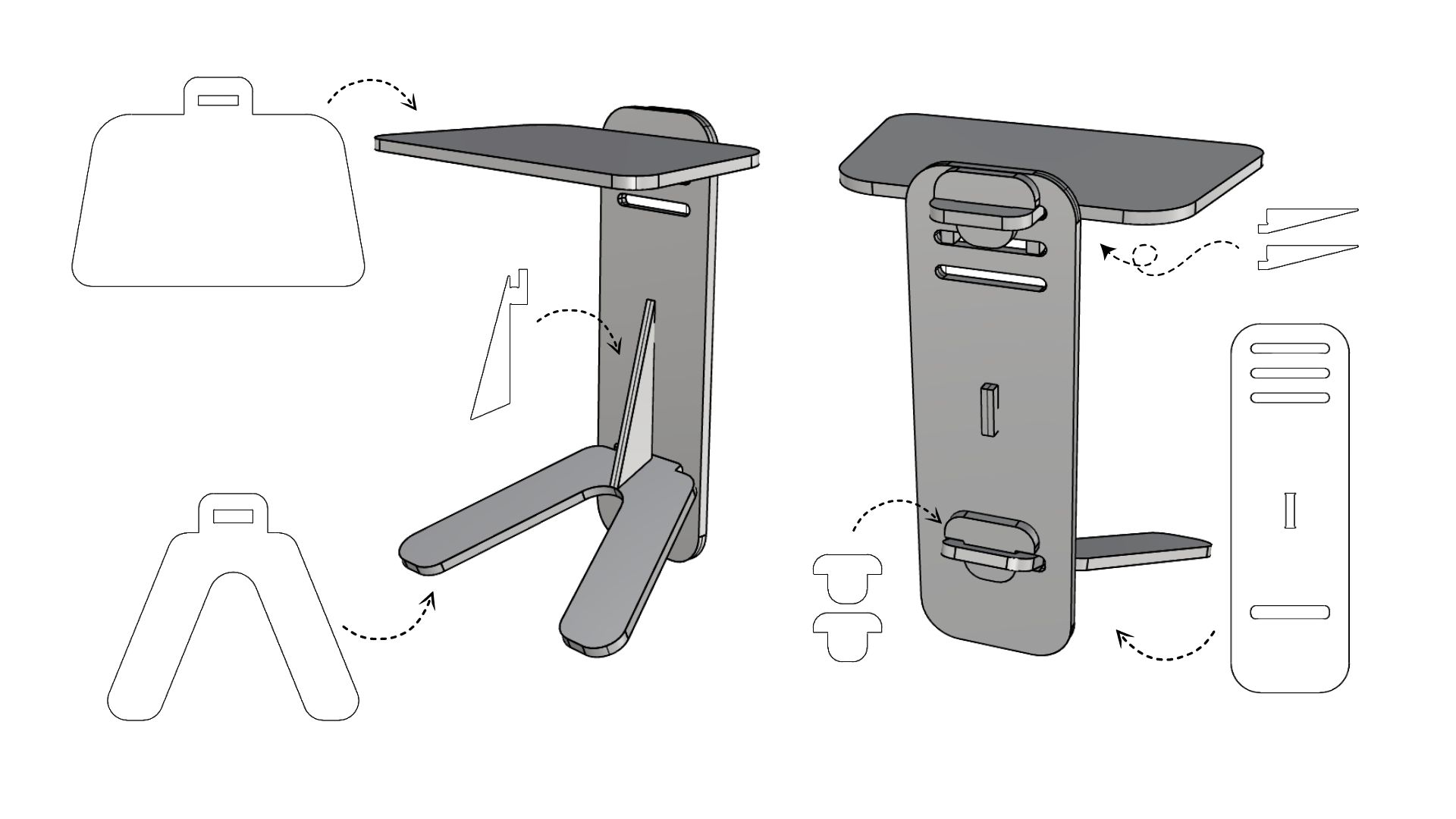
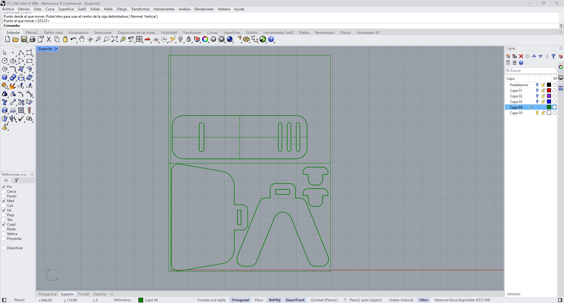
The following images show the modeling process and validation in Rhinoceros.
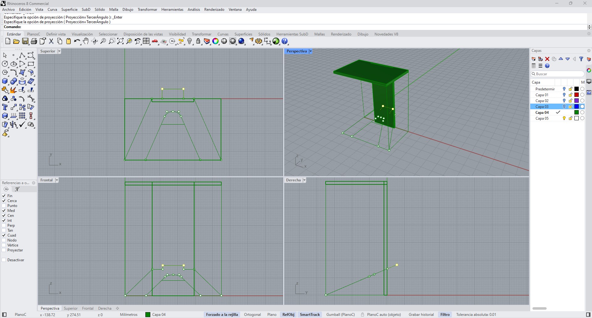
2D base geometries and construction lines used to define the components.
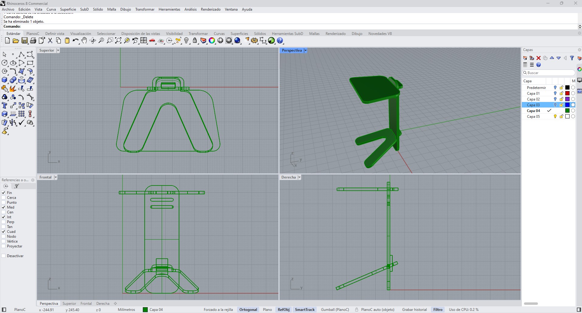
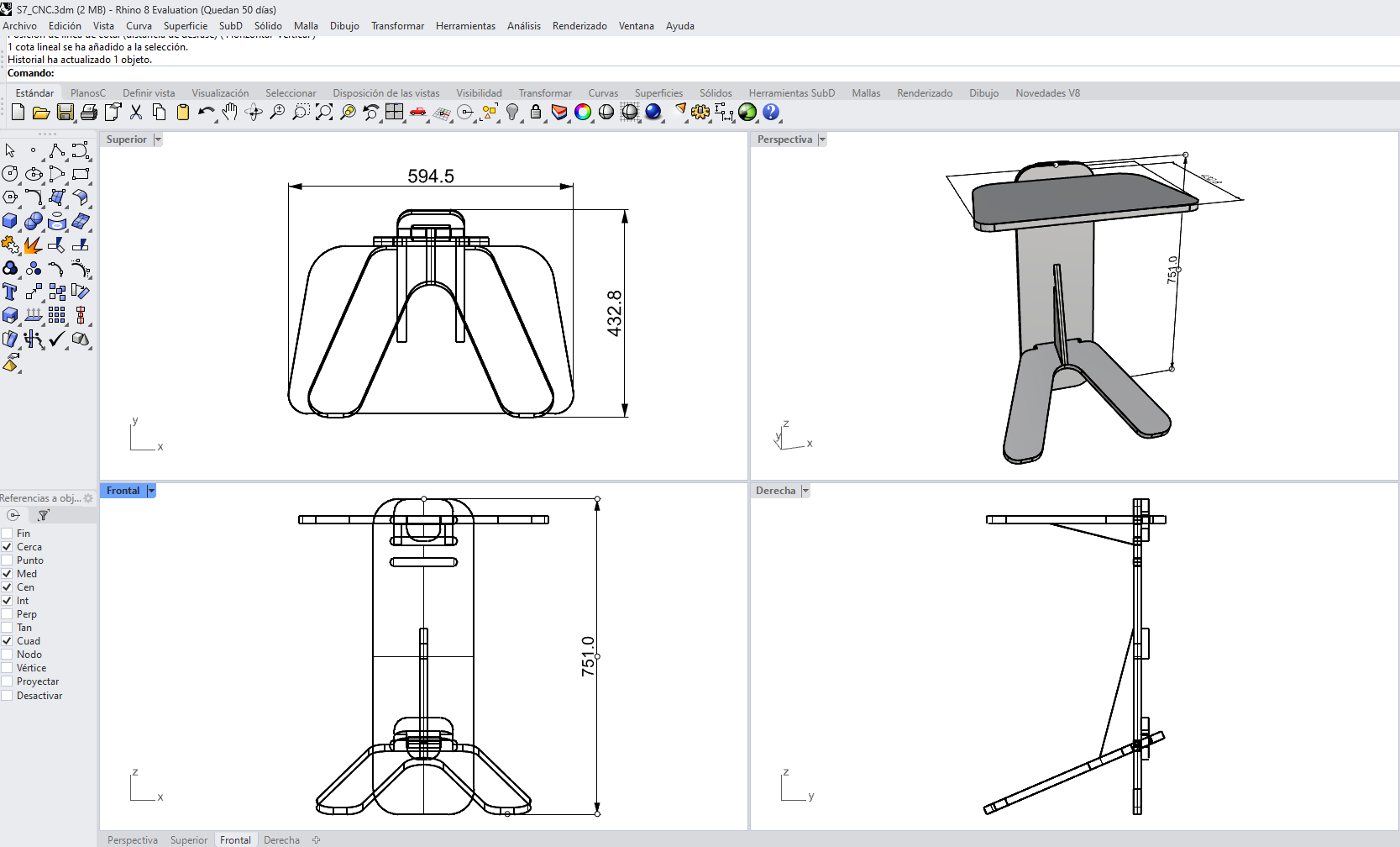
Orthographic views (top, front, side) used to validate dimensions and alignment.
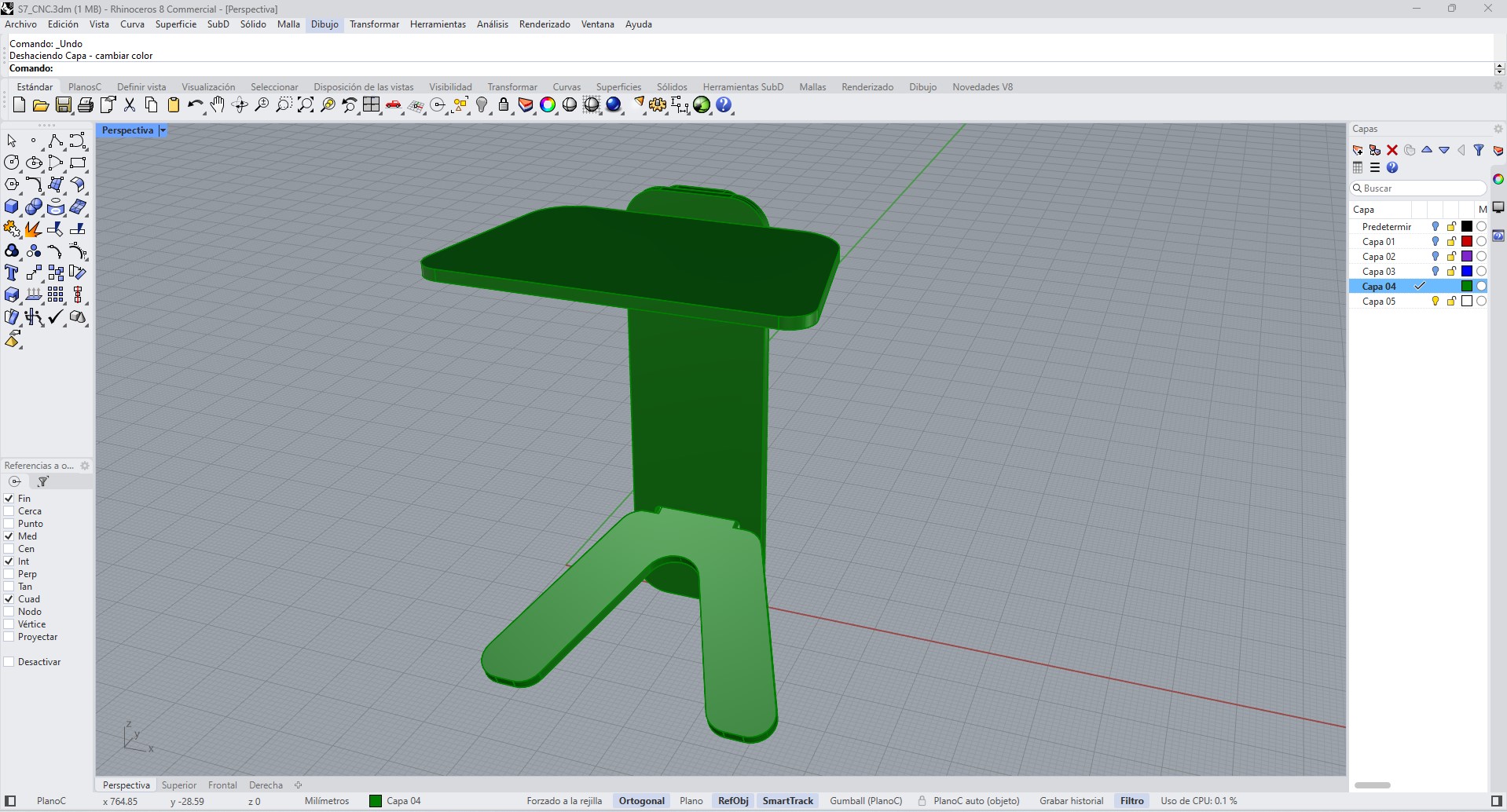
3D assembly used to evaluate overall proportions and structural configuration.
At this stage, it was important to consider the material thickness, since the slots and joints had to match the actual thickness of the OSB board. From the design stage, a slot-joint system was proposed, intended to be assembled by pressure fit.
1.1 Plan View and Dimensional Definition
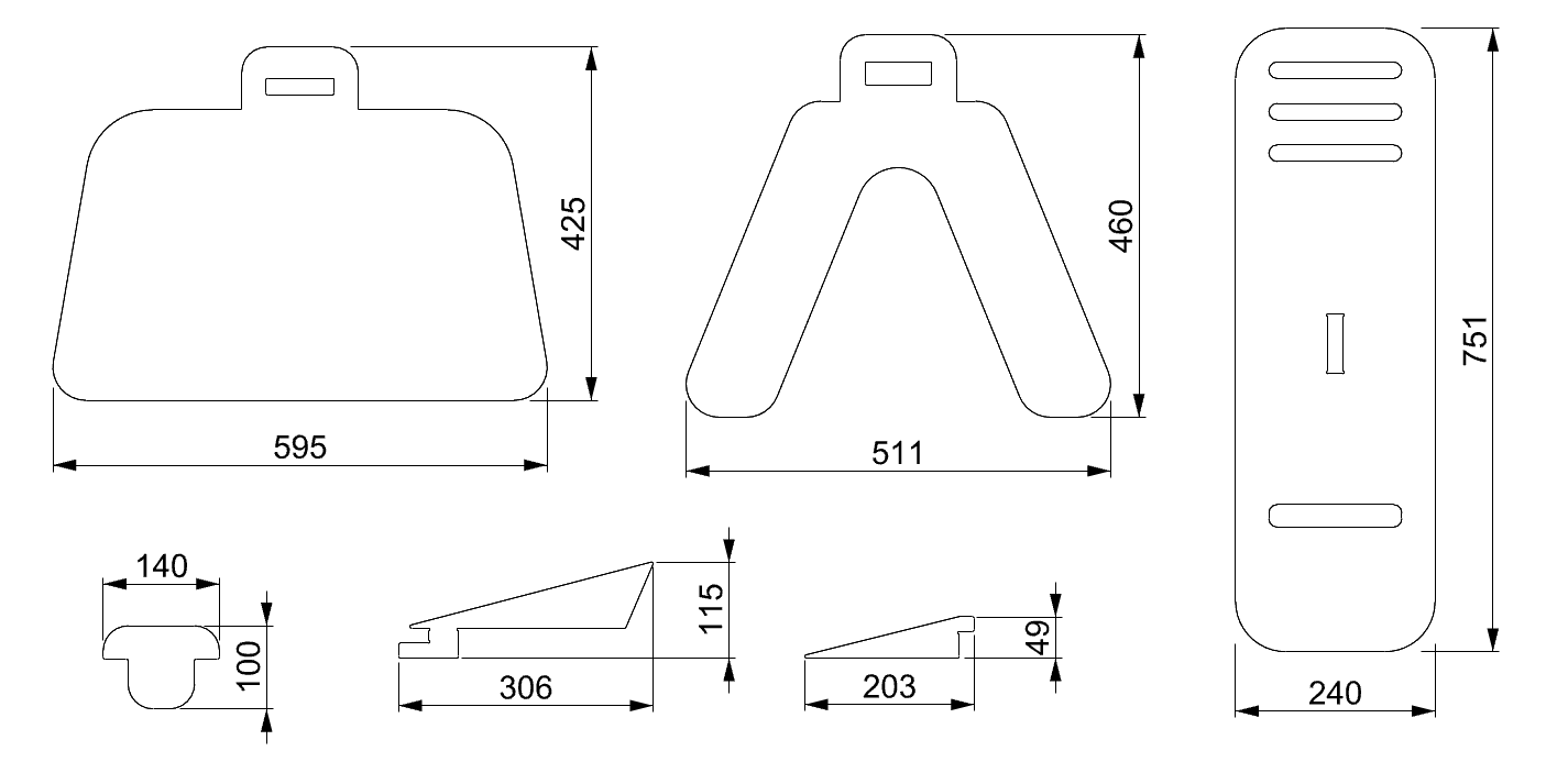
The design was defined through a dimensional analysis of the assembled structure, using orthographic projections to validate proportions, stability, and component relationships. The plan view (top view) was used to establish the overall footprint of the object and to verify the spatial distribution of the base elements in relation to the top surface.
The top board has an approximate width of 594.5 mm, which defines the main functional area of the table. The depth of the structure, measured from the extremities of the base, reaches approximately 432.8 mm, ensuring sufficient support and preventing tipping.
The total height of the object is 751 mm, determined by the vertical panel dimension. This element acts as the main structural axis, connecting the top surface with the base and transferring loads efficiently.
These dimensions were defined considering both ergonomic proportions and fabrication constraints, particularly the available CNC working area (600 × 900 mm) and the standard size of the OSB board used.
All dimensions are expressed in millimeters and were adjusted to match the real material thickness and machining tolerances.
1.2 Technical Description of Components
The system is composed of a set of interlocking flat components designed to be fabricated using CNC machining and assembled without additional hardware. Each component fulfills a specific structural and functional role within the system.
The top board functions as the primary load-bearing surface. It includes a central slot that allows it to connect with the vertical panel. Its geometry distributes loads evenly and provides a stable working surface.
The vertical panel acts as the main structural spine of the system. It connects the top and base elements, transferring loads downward while maintaining alignment. This component also integrates multiple slots that enable the insertion of locking and reinforcement elements.
The base structure is composed of two angled legs that extend outward from the central axis. This configuration increases the support area and improves stability by lowering the center of gravity and reducing the risk of lateral tipping.
The internal reinforcement element connects the vertical panel with the base, increasing structural rigidity and preventing deformation under load. This element is critical for maintaining the integrity of the system during use.
The wedge components act as mechanical locking elements. Once inserted into the corresponding slots, they generate friction and compressive forces between parts, securing the assembly without the need for screws, adhesives, or external fasteners.
All connections are based on press-fit joints. The slot dimensions were defined according to the material thickness (19 mm OSB), with slight tolerances to compensate for machining variability and ensure a tight fit.
1.3 Fabrication Considerations
The design was developed considering the constraints of CNC machining. The tool diameter (3.175 mm) influenced internal corner geometries, requiring adaptations to ensure proper fitting between parts.
Material behavior was also considered. OSB, being a composite wood material, presents variability in density and edge quality, which affects the precision of press-fit joints. For this reason, slot dimensions were tested and adjusted to achieve a balance between ease of assembly and structural rigidity.
Additionally, the layout of parts was optimized to fit within the available board dimensions, reducing material waste and improving fabrication efficiency.
2. Part Layout
Once the design was defined, the parts were arranged for fabrication.
Due to the size of the object and the usable working area of the machine, the parts were distributed across two 60 × 90 cm boards. This decision made it possible to fit all components correctly within the available format, maintaining enough spacing between parts and facilitating the subsequent generation of toolpaths.
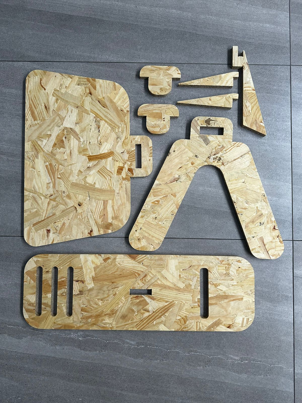
The following image shows the cut parts laid out on the floor before assembly.
The produced parts included:
- a large top surface
- an elongated base
- a lateral structural support piece
- small connection and reinforcement parts
- additional elements for later correction
This arrangement into two boards also made the machining process easier to manage and reduced material waste.
3. CAM Preparation in Fusion 360
After modeling the parts in Rhinoceros, the process continued in Autodesk Fusion 360, specifically in the Manufacture workspace, to prepare the CNC machining process.
In Fusion 360, the manufacturing process was configured by defining:
- material definition
- coordinate system selection
- origin positioning
- tool selection
- toolpath generation
- cut simulation
- CNC code export
The screenshots of the process show how this stage was built step by step.
3.1 Material Setup
In the CAM module, the first step was to create the manufacturing Setup, defining the stock material on which the cutting process would be performed.
In this configuration, the board dimensions were set to 600 × 900 mm, with an approximate thickness of 19 mm.
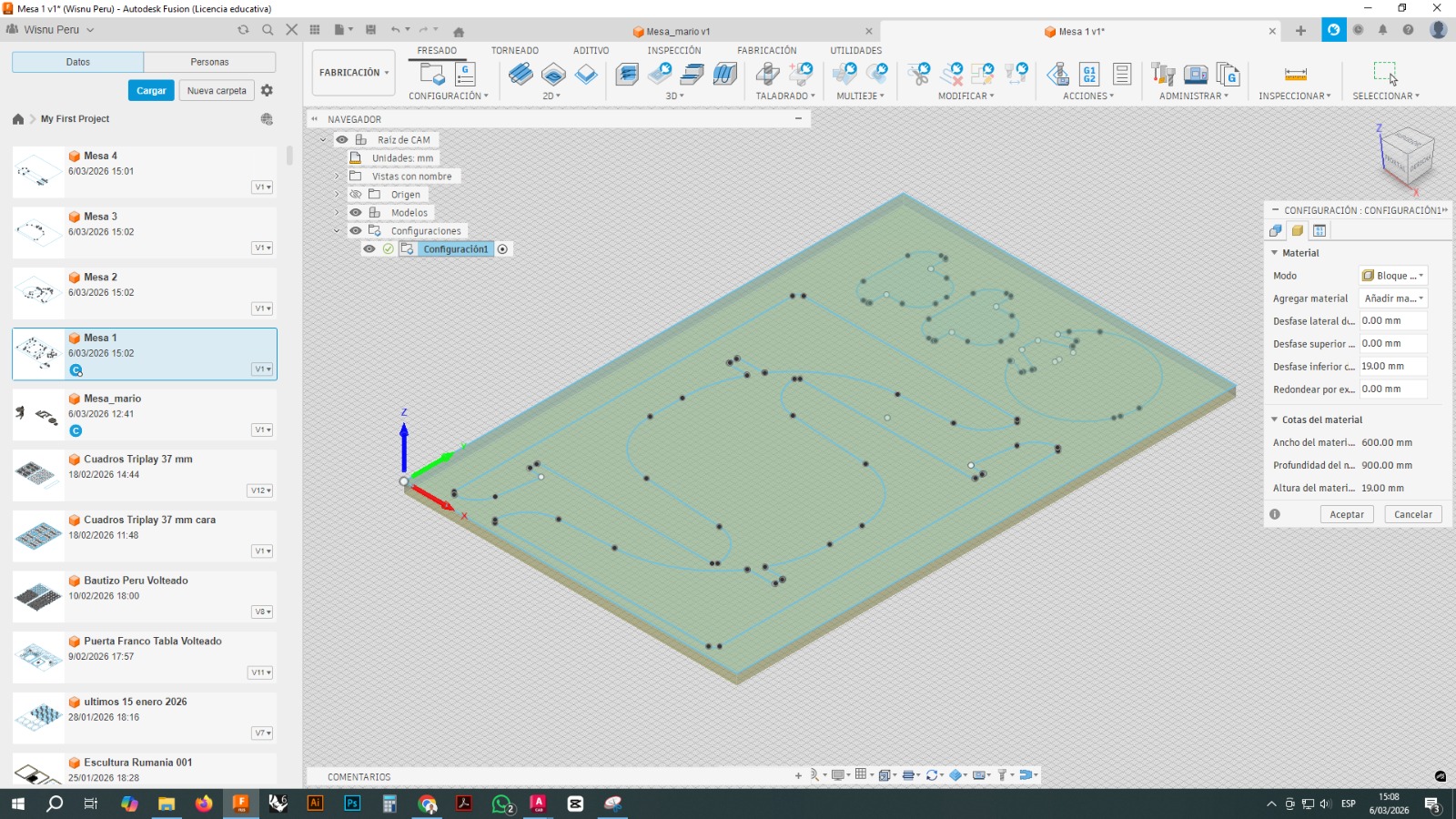
This stage is important because the entire logic of the toolpaths depends on the correct definition of the material, its limits, and the origin position.
3.2 Tool Selection
A 3.175 mm flat end mill was used for machining. The tool was selected from the Fusion 360 tool library.
The configuration included parameters such as:
- tool diameter: 3.175 mm
- tool type: flat end mill
- spindle speed: 20000 rpm
- feed rate: 1800 mm/min
- lead-in and lead-out feed rate: 1500 mm/min
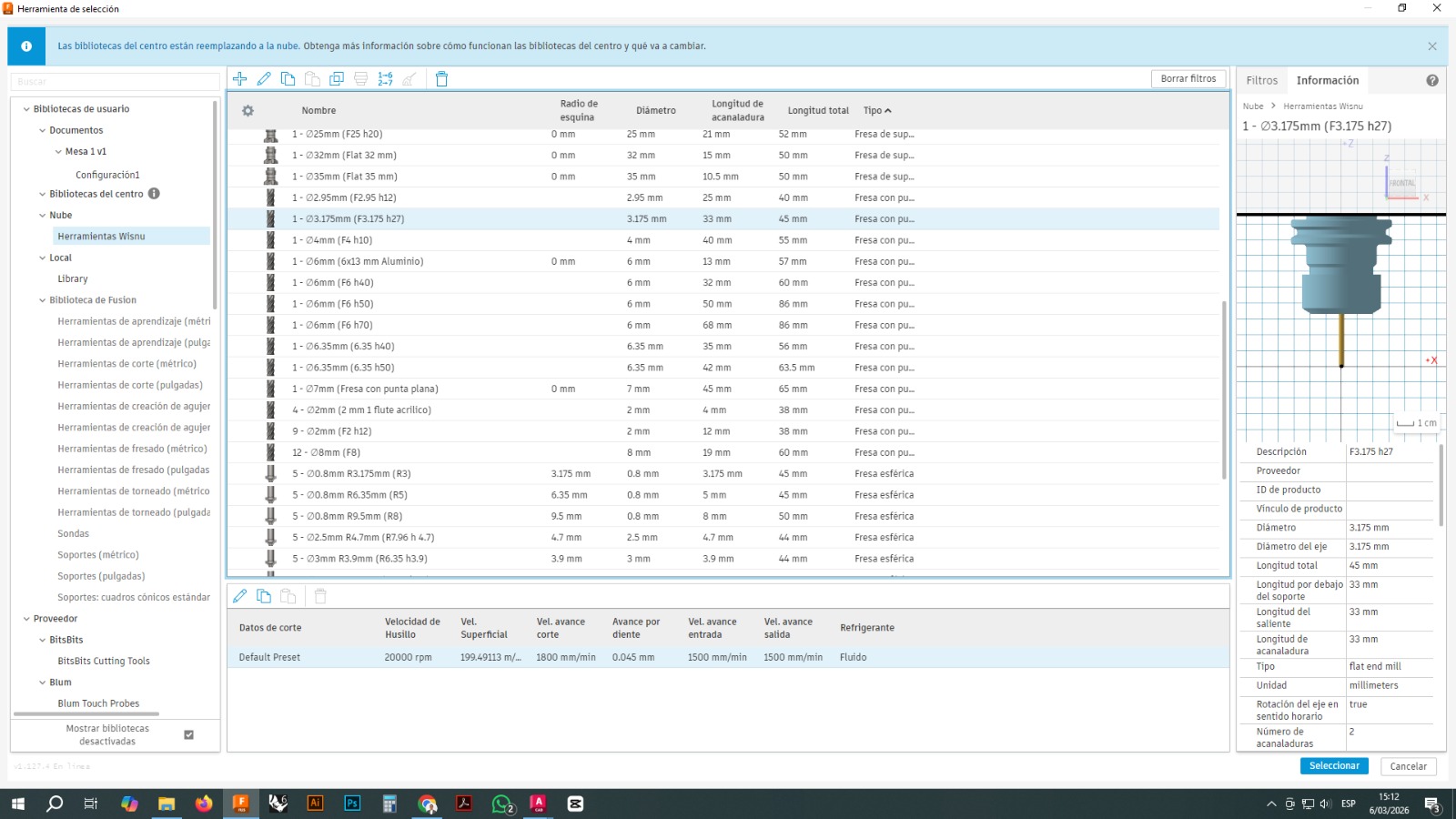
This tool was chosen because it allowed relatively precise cuts in OSB and made it possible to machine small slots and contours.
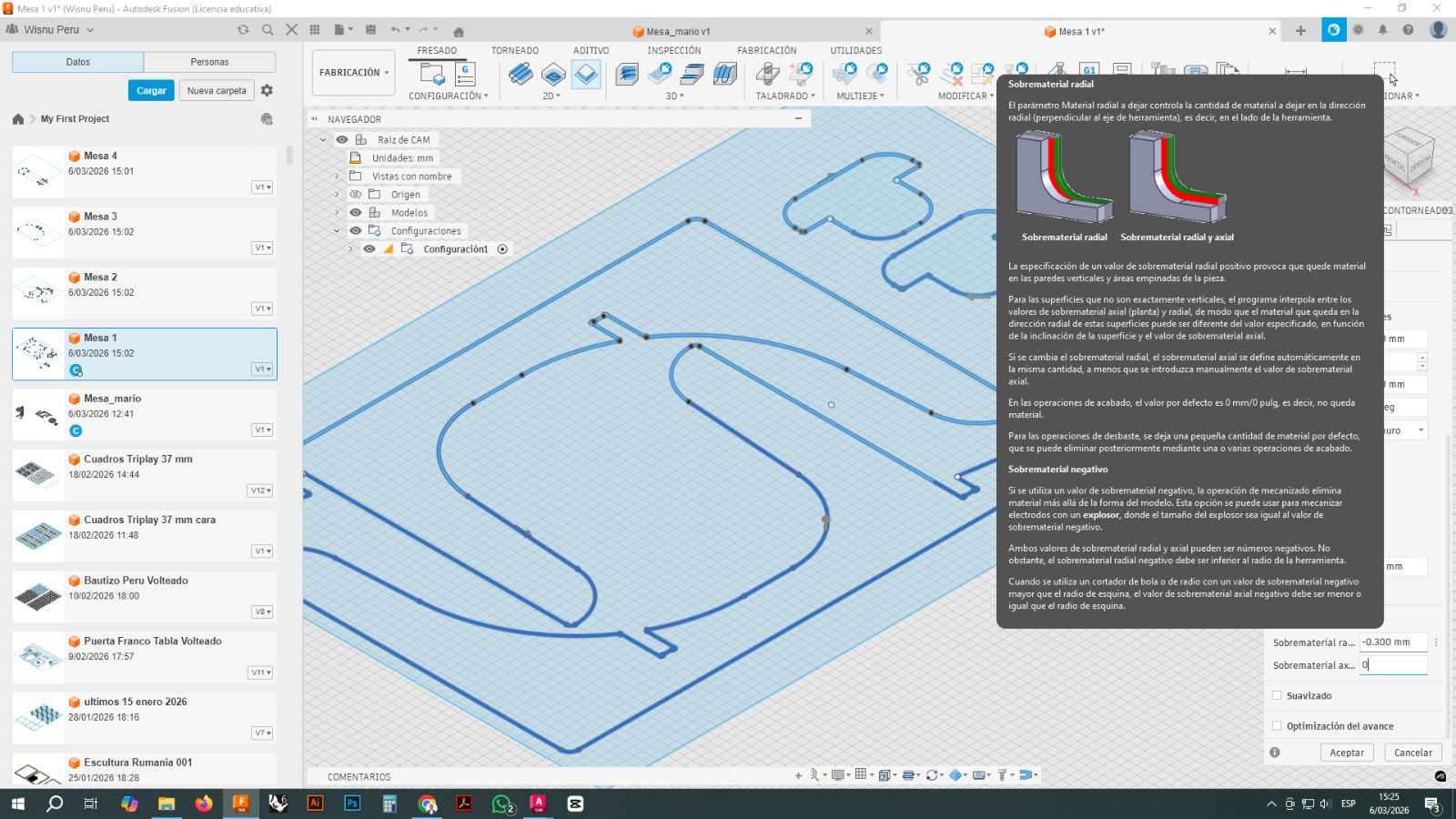
3.3 Toolpath Generation
The main strategy used was 2D Contour, which is suitable for cutting closed profiles and separating parts from the board.
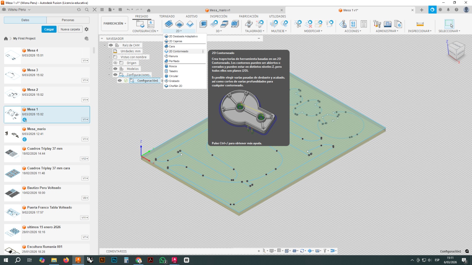
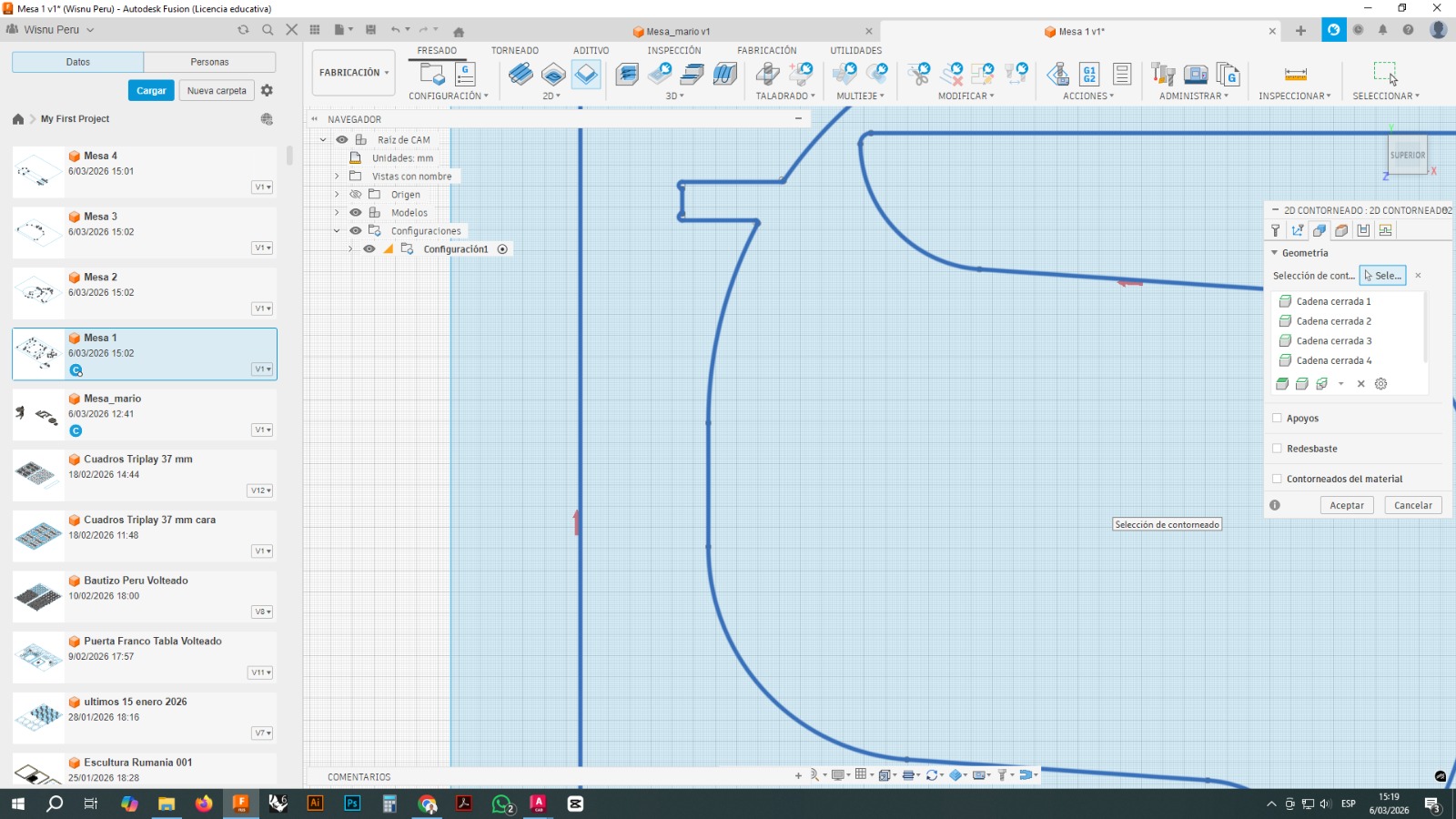
From this operation, the closed chains corresponding to each part were selected. The toolpath was generated by following the edges of each contour, and different parameters were configured to ensure that the tool would cut completely through the material without compromising the stability of the parts during machining.
3.4 Tabs or Holding Bridges
To prevent the parts from coming loose before the machining process was finished, tabs, or small bridges of material, were added.
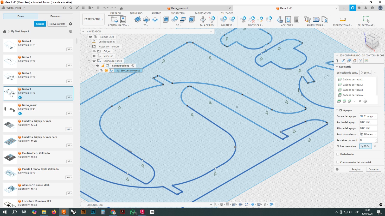
These tabs kept the parts attached to the board while the tool finished its path. After cutting, these small bridges were manually removed.
Adding tabs was essential to prevent part movement, vibrations, or errors during the final cutting passes.
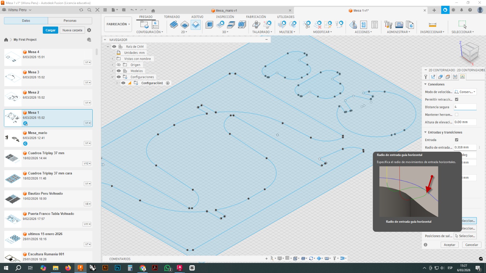
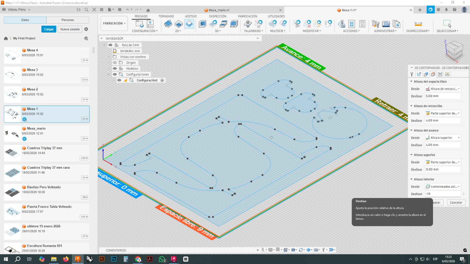
3.5 Heights and Linking Moves
In Fusion 360, safety heights and tool entry and exit movements were also configured.
The parameters visible in the screenshots included:
- retract height
- top height
- bottom height
- clearance height
- safe distance
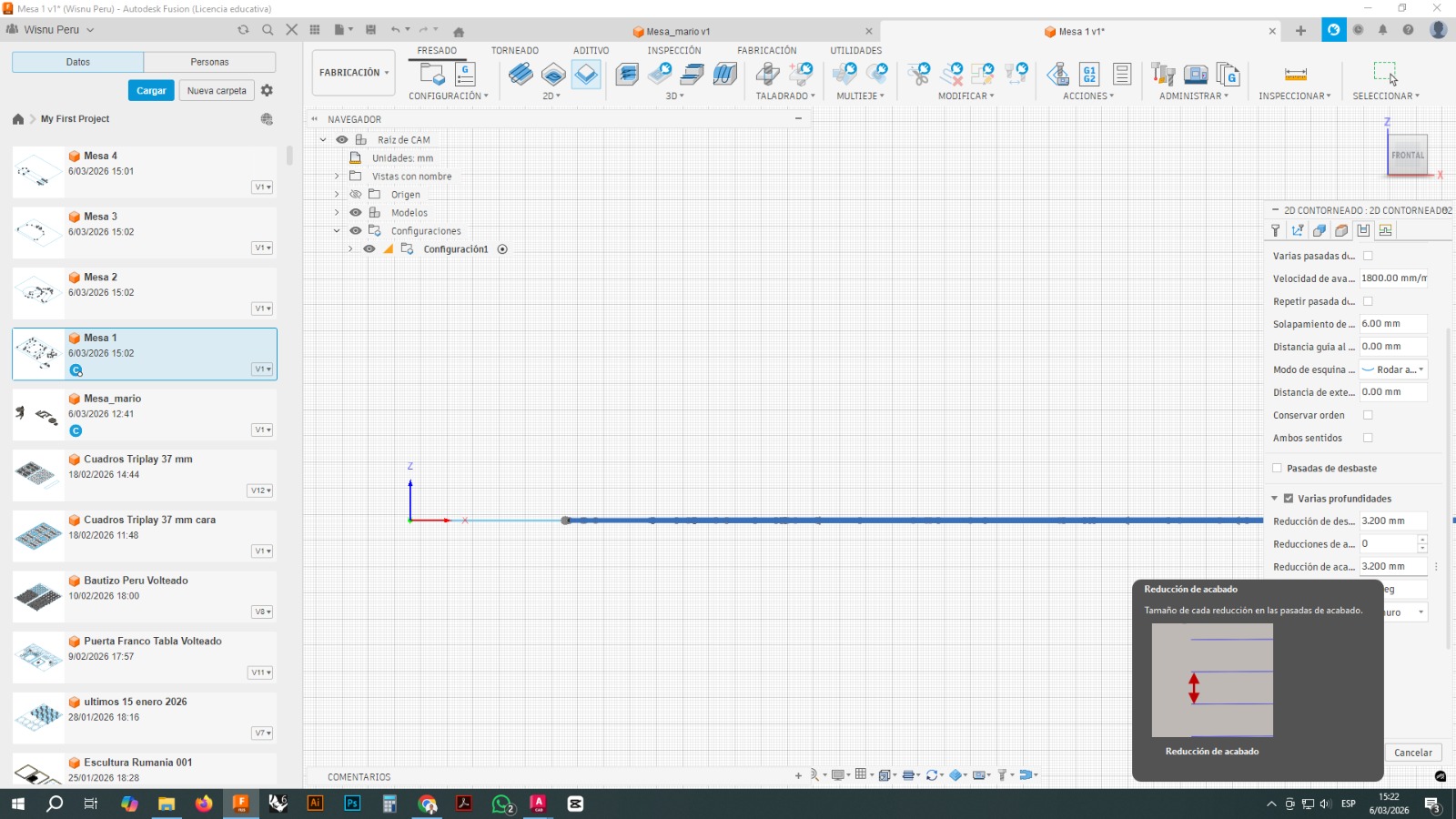
These settings help avoid collisions and control how the tool enters and exits the material.
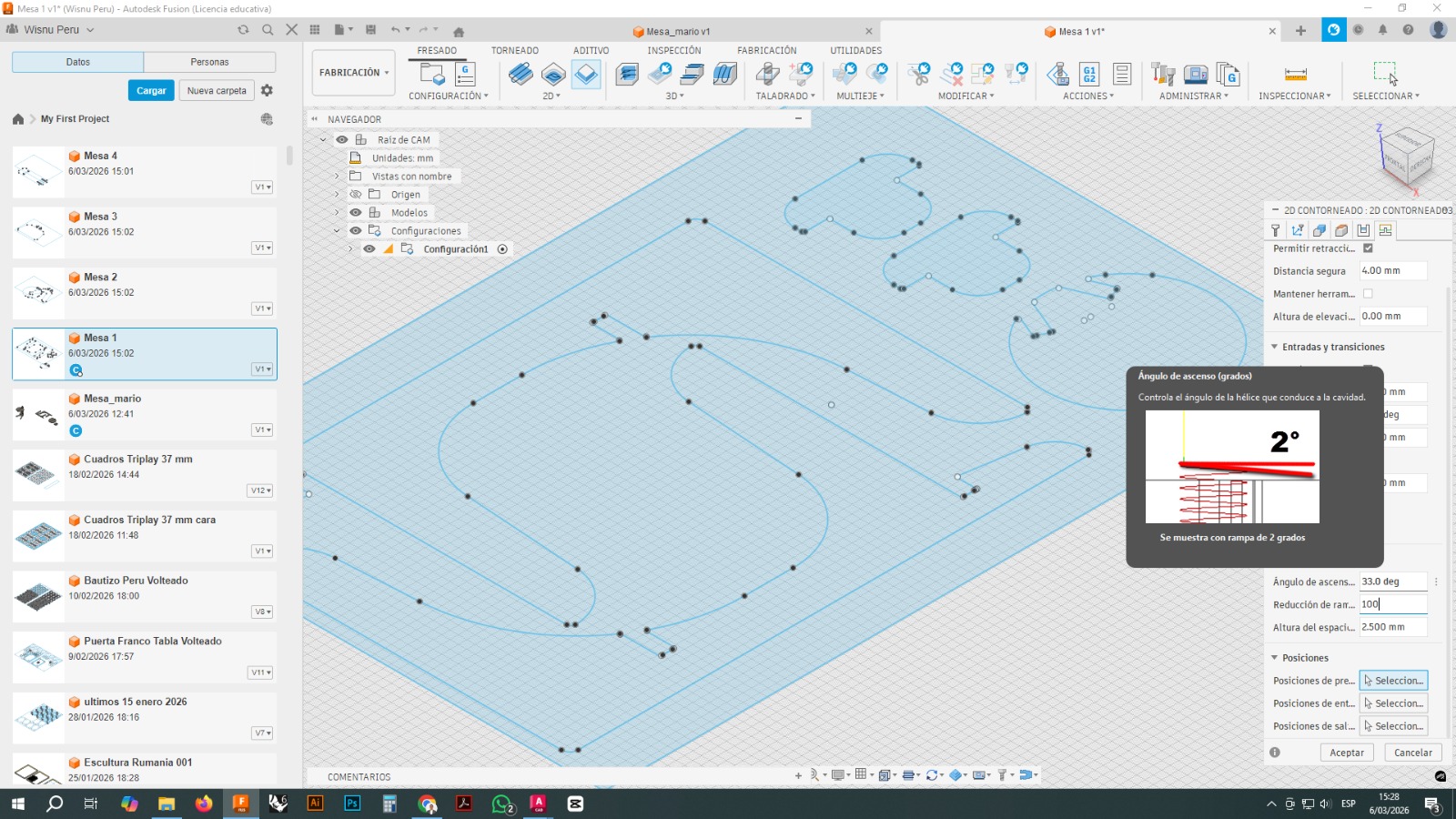
Additional parameters were also adjusted, such as:
- lead radius
- toolpath linking moves
- retraction moves
- preservation of cutting order
3.6 Cutting Depth per Pass
Since the material had a thickness close to 19 mm, the machining was not done in a single pass. Instead, multiple depths were configured.
This made it possible to divide the total cut into several successive layers, reducing tool stress and improving process safety.
Working in multiple passes is especially important with materials such as OSB, since it reduces the risk of tool breakage, vibration, or poor edge quality.
3.7 Machining Simulation
Before exporting the final file, the toolpath simulation was run in Fusion 360.
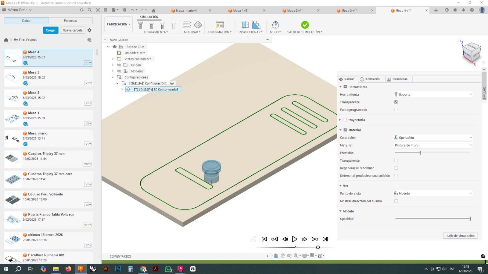
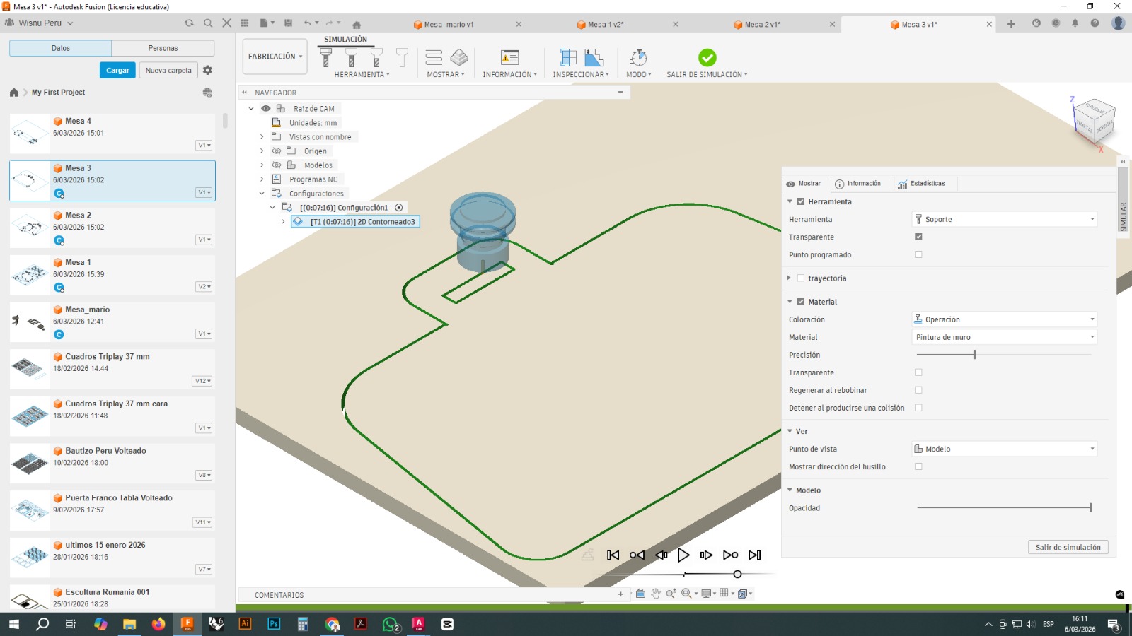
The simulation allowed verification of:
- cutting direction
- toolpath sequence
- machining depth
- possible interferences
- overall tool movement behavior
The simulation also helped identify details that could create problems during the real cutting process.
3.8 Code Export
Once the CAM process was validated, the CNC file was exported as machine code. The file was reviewed before being sent to the machine control software.
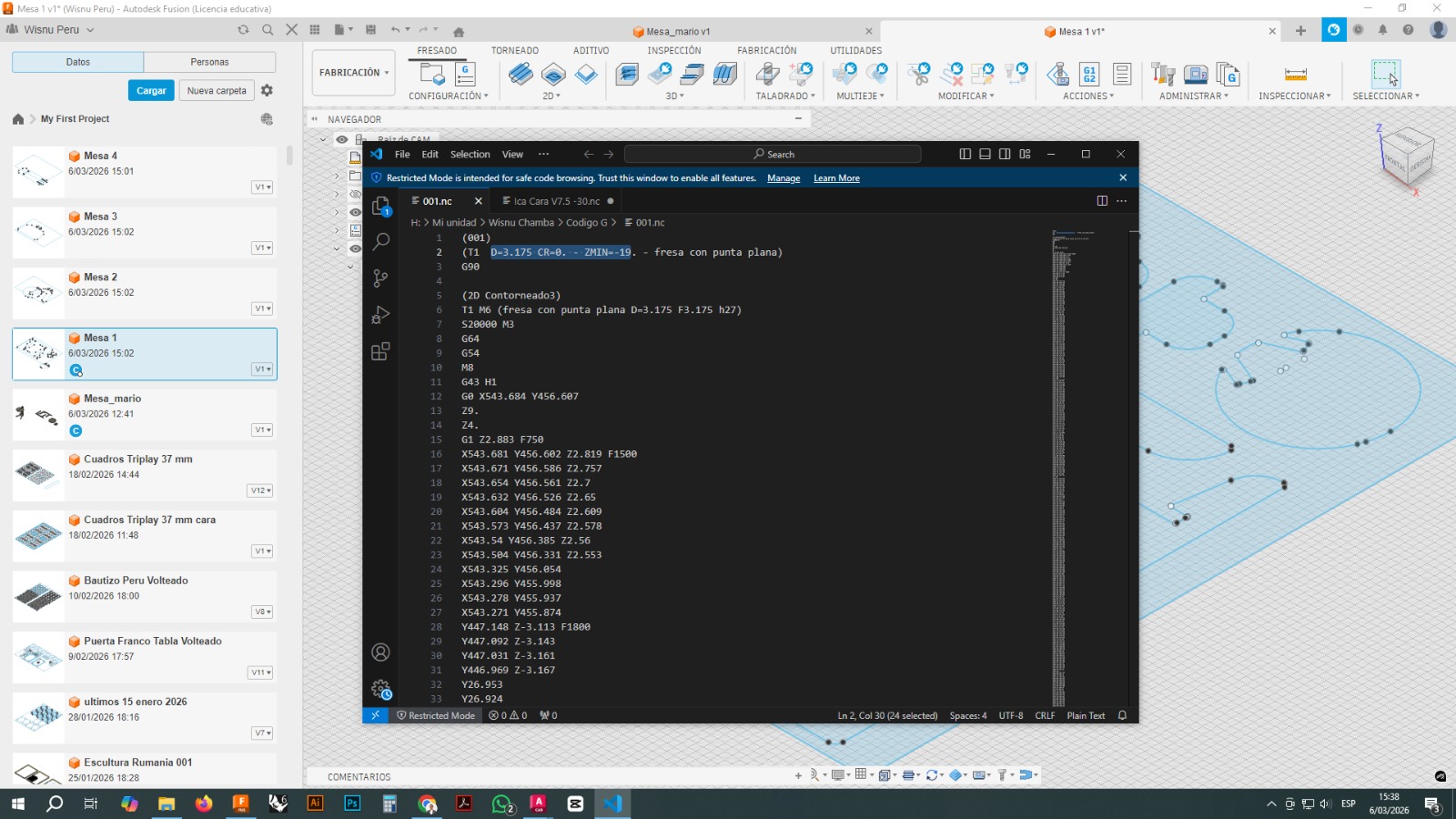
The code review made it possible to verify that the file correctly contained:
- tool call
- spindle speed
- movement coordinates
- cutting depths
- cutting sequence
4. Machine Used
The parts were machined on an i2R CNC router with a working area of approximately 60 × 90 cm.
The i2R is a numerical control machine suitable for working with sheet materials such as wood, MDF, plywood, OSB, and some plastics. Its size makes it appropriate for medium and large projects, as long as the parts are arranged within its working area.
The observed machine features included:
- 60 × 90 cm working area
- X, Y, and Z axis motion
- high-speed spindle
- sheet fixation on a flat bed
- dust extraction system
- control through CNC software
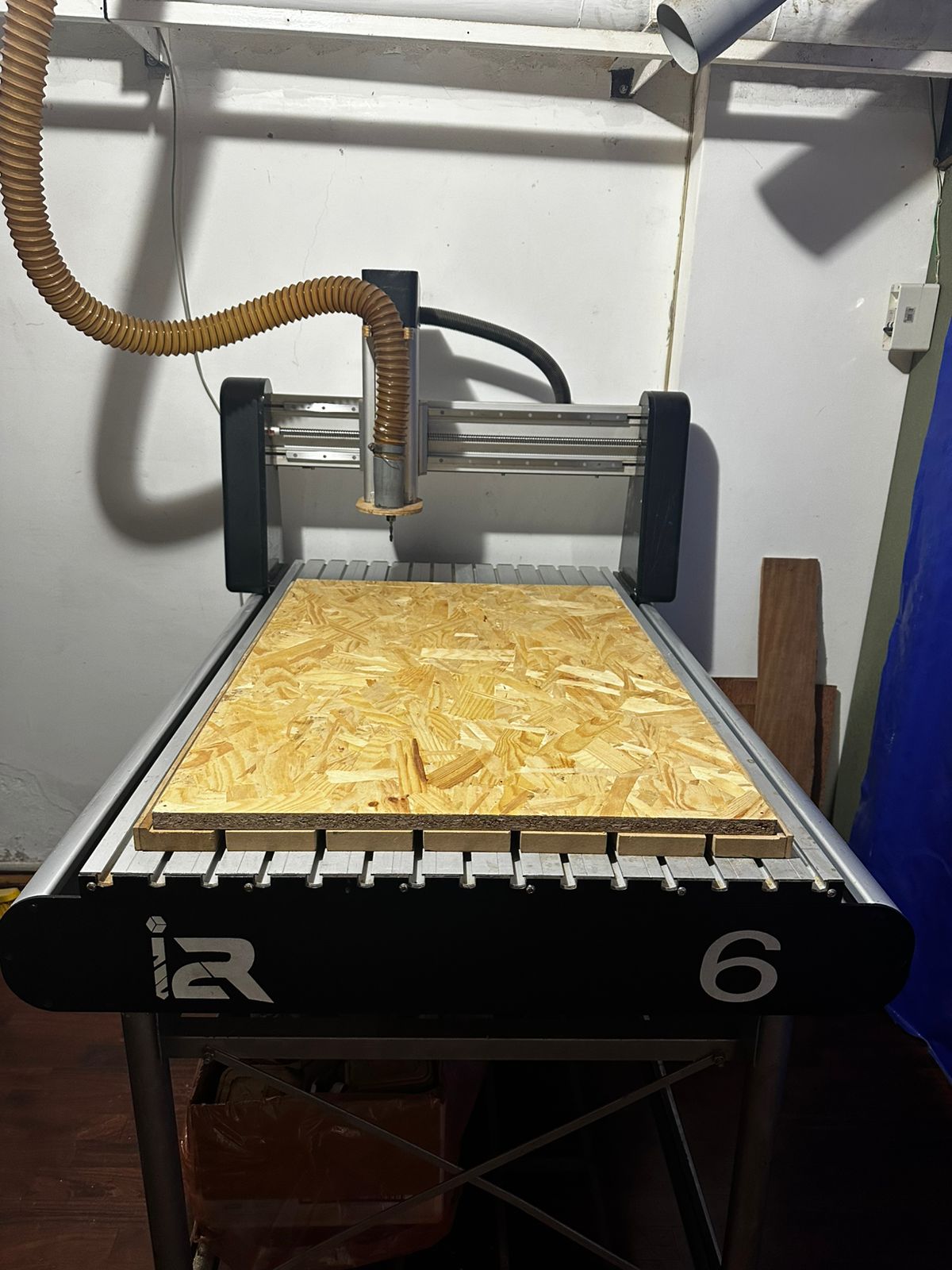
The main limitation of this machine in this project was precisely the working format, which is why the parts had to be distributed across two 60 × 90 cm boards.
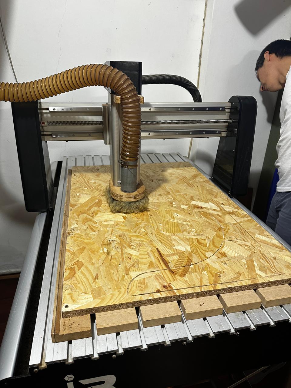
5. Machine Preparation
Before cutting, several physical preparation steps were carried out on the CNC machine.
First, the board was placed on the machine bed and properly fixed to prevent displacement.
The selected tool was then installed in the spindle.
The set of available cutting tools in the lab was also reviewed in order to identify the most suitable tool for the job.
Finally, the file was loaded into the machine control software.
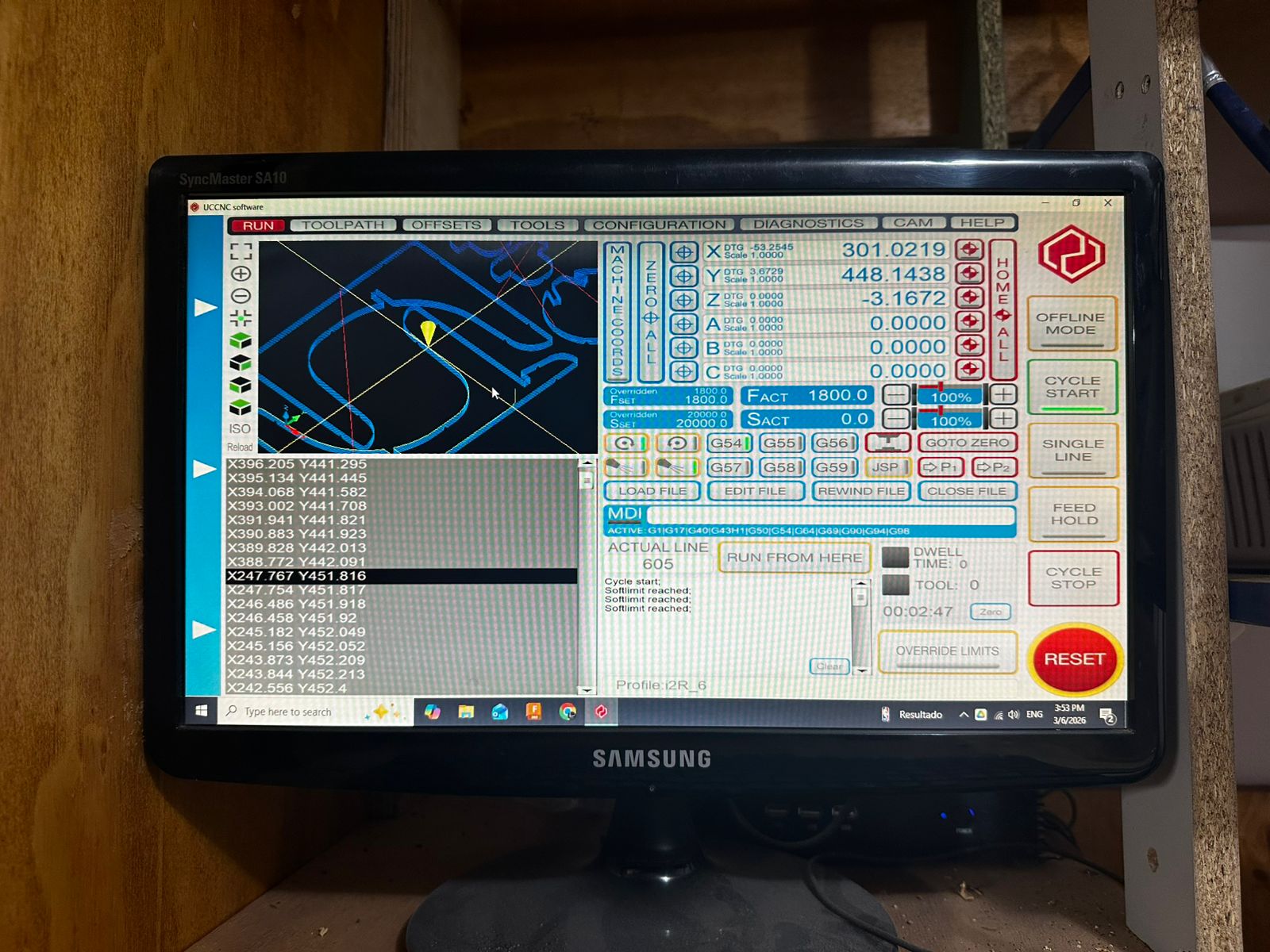
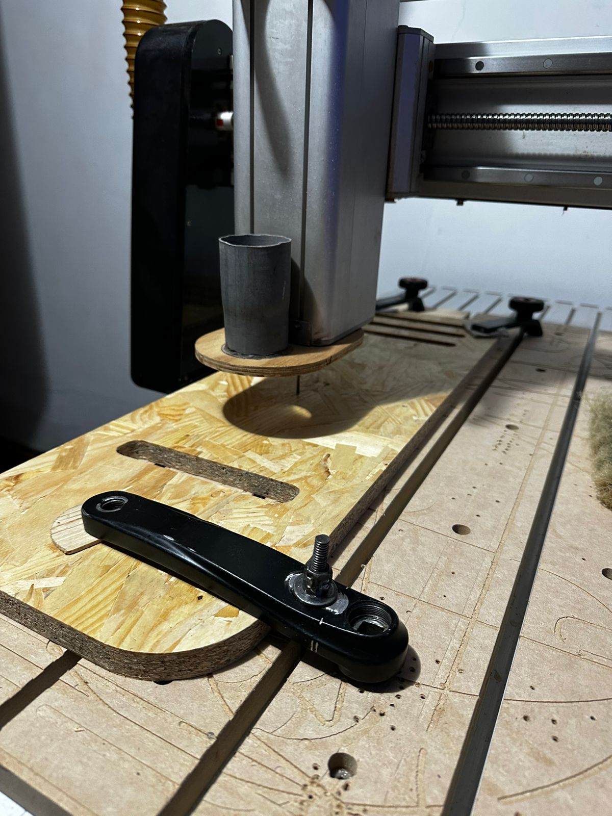
6. Cutting Process
Once the file was configured and the machine was prepared, the machining process was executed.
The cut followed the toolpaths previously generated in Fusion 360. During this stage, it was verified that:
- the tool correctly followed the contours
- the board remained stable
- there was no excessive vibration
- the cutting depth was appropriate
- the parts remained held by the tabs until the end
At the end of the process, the parts were removed from the board and the areas where the small holding tabs remained were cleaned.
7. Prototype Assembly
Once all the parts had been cut, the prototype was assembled.
The following image shows the assembled result.
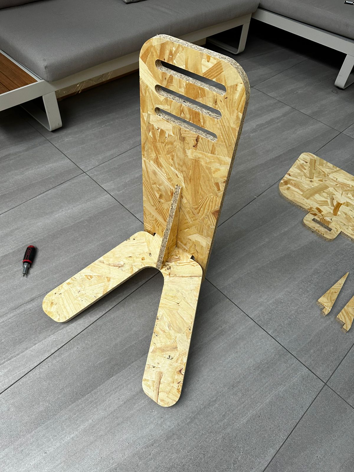
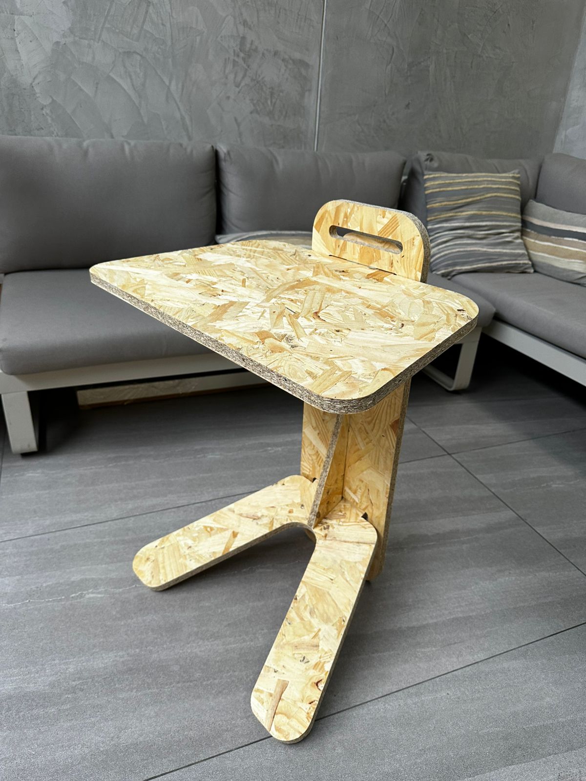
The resulting object was a disassemblable side table made of interlocking parts and supports that hold a horizontal surface.
The following aspects of the real design behavior were evaluated during this stage:
- structural stability
- joint tightness
- top surface angle
- relationship between base and support
- ease of assembly and disassembly
The prototype made it possible to validate the general logic of the system, but it also revealed issues that were not as evident in the digital model.
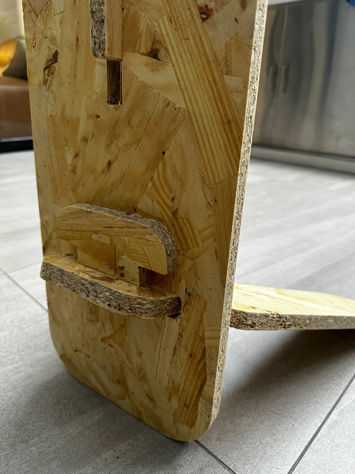
8. Iteration and Redesign
After the first assembly, it became clear that the design required adjustments.
In particular, it was observed that:
- additional elements were needed to improve stability
- the angle of the table needed correction
- some parts had to be redesigned to improve the overall behavior of the structure
For this reason, after producing the first cuts and assembling the prototype, several parts were redesigned. This second revision helped correct structural problems and improve the ergonomics of the object.
The proposed modifications included:
- the incorporation of additional reinforcements
- adjustments to the angle of the top plane
- corrections to support pieces
- improvements to the relationship between the base and the vertical structure
This process was important because it showed that CNC cutting does not end with fabrication itself, but forms part of a cycle of testing, evaluation, and improvement.
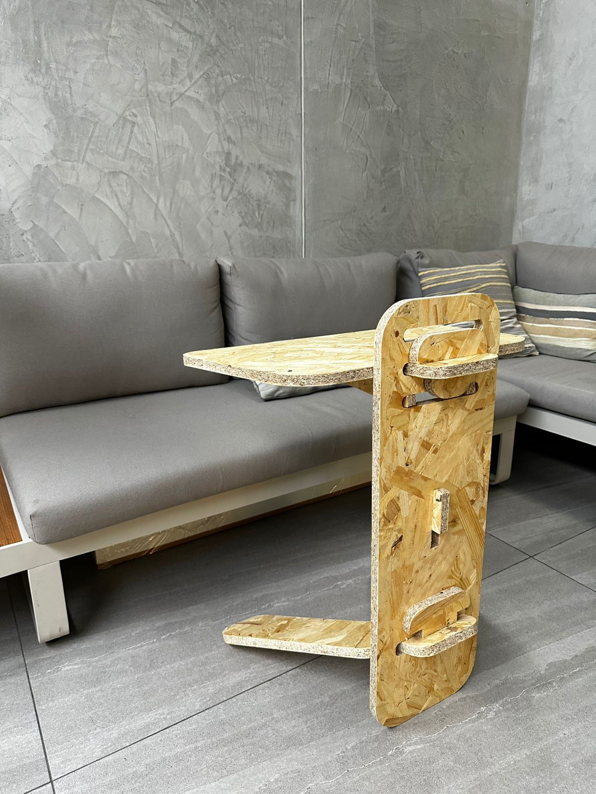
9. Result
The project made it possible to fabricate a large object from flat CNC-machined parts, fulfilling the objective of this week.
Beyond the physical result, the exercise also made it possible to go through the complete workflow:
- modeling in Rhino
- CAM preparation in Fusion 360
- simulation and validation
- code export
- machining on the i2R
- physical assembly
- correction and iteration
10. Learning Outcomes
This exercise made it possible to understand in a practical way how digital design is integrated with large-scale fabrication through CNC machining.
The main learning outcomes were:
- the importance of designing while considering the actual thickness of the material
- the need to plan the object according to the usable area of the machine
- how to organize parts within limited boards, in this case two 60 × 90 cm sheets
- the relevance of correctly defining the tool, heights, tabs, and depths in CAM software
- the value of prior simulation to detect errors before the actual cut
- the importance of performing a physical assembly to validate stability, angles, and structural behavior
The work also made it clear that CNC prototyping is an iterative process. Even when the digital model looks correct on screen, the real assembly reveals issues that require redesign and improvement.
Download Files
The design files used in this assignment can be downloaded below.