
Week 07 — CNC Machine Characterization
Group Assignment
During the group assignment, we carried out the characterization of the CNC machining process available in the laboratory. The objective was to understand the complete digital manufacturing workflow using the lab CNC router, from the CAD design stage to G-code generation and the physical execution of the machining process.
This activity allowed us to analyze not only the operation of the machine itself, but also the relationship between design decisions, machining parameters, cutting tools, and material behavior during fabrication.
The main aspects studied during this process were:
- Safety training
- Machine characteristics
- Available cutting tools
- CAD–CAM–CNC workflow
- Machining parameters
- Cutting strategies
Understanding these elements is essential to correctly prepare files before executing any CNC operation and to avoid errors that may affect both the final part and the machine.
1. Safety Training
Operating a CNC router involves risks related to high-speed rotating tools, chip generation, and automated axis movement. For this reason, strict safety procedures must always be followed before and during machine operation.
Personal Safety Measures
Before operating the CNC machine, the following precautions must be taken:
- Wear safety glasses to protect against flying chips and debris.
- Avoid loose clothing, jewelry, or long hair near the spindle.
- Use hearing protection when machining for extended periods.
- Ensure that the dust extraction system is active during cutting.
- Never place hands near the tool while the machine is operating.
- Do not leave the machine unattended during machining.
Machine Safety
Before starting a job, it is necessary to verify the following:
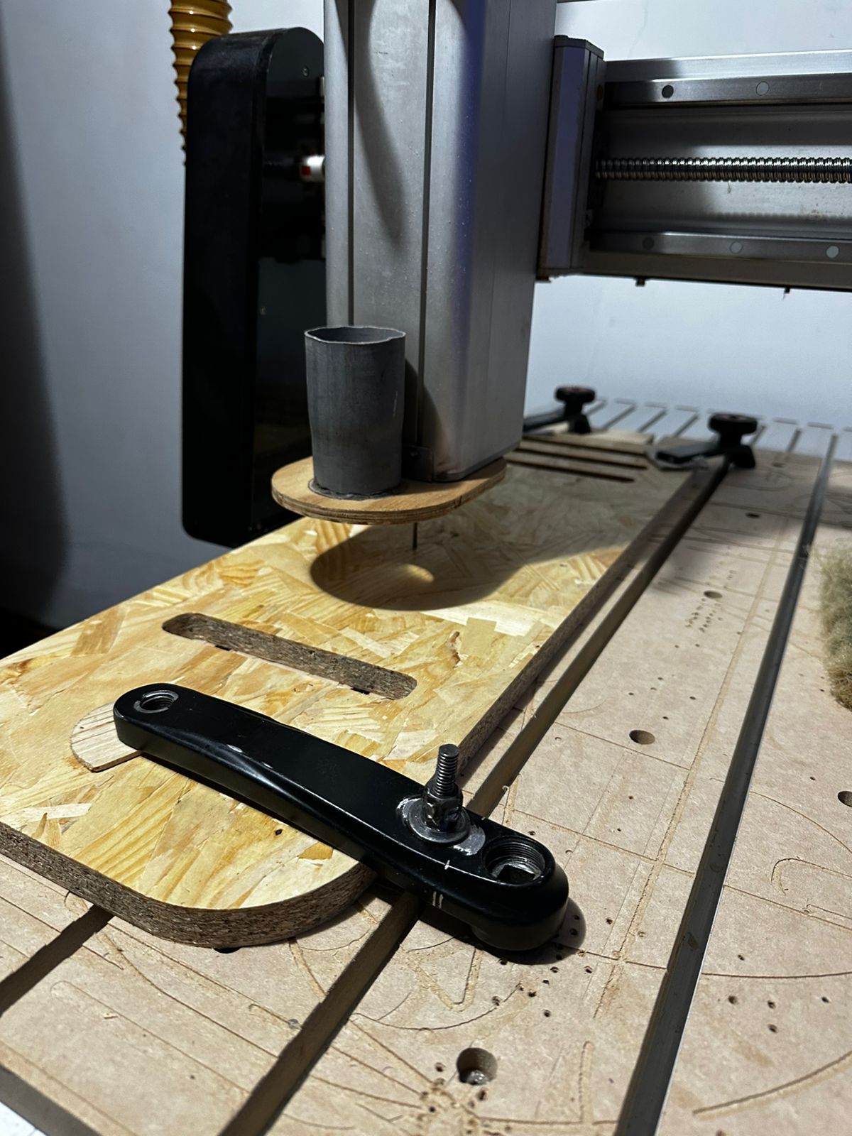
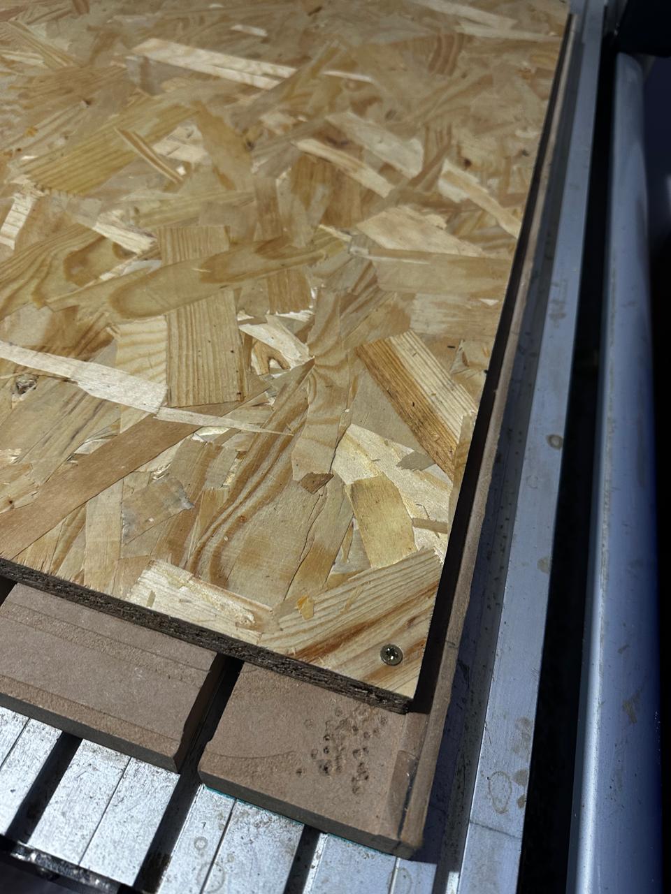
- The workpiece is securely fixed to the table.
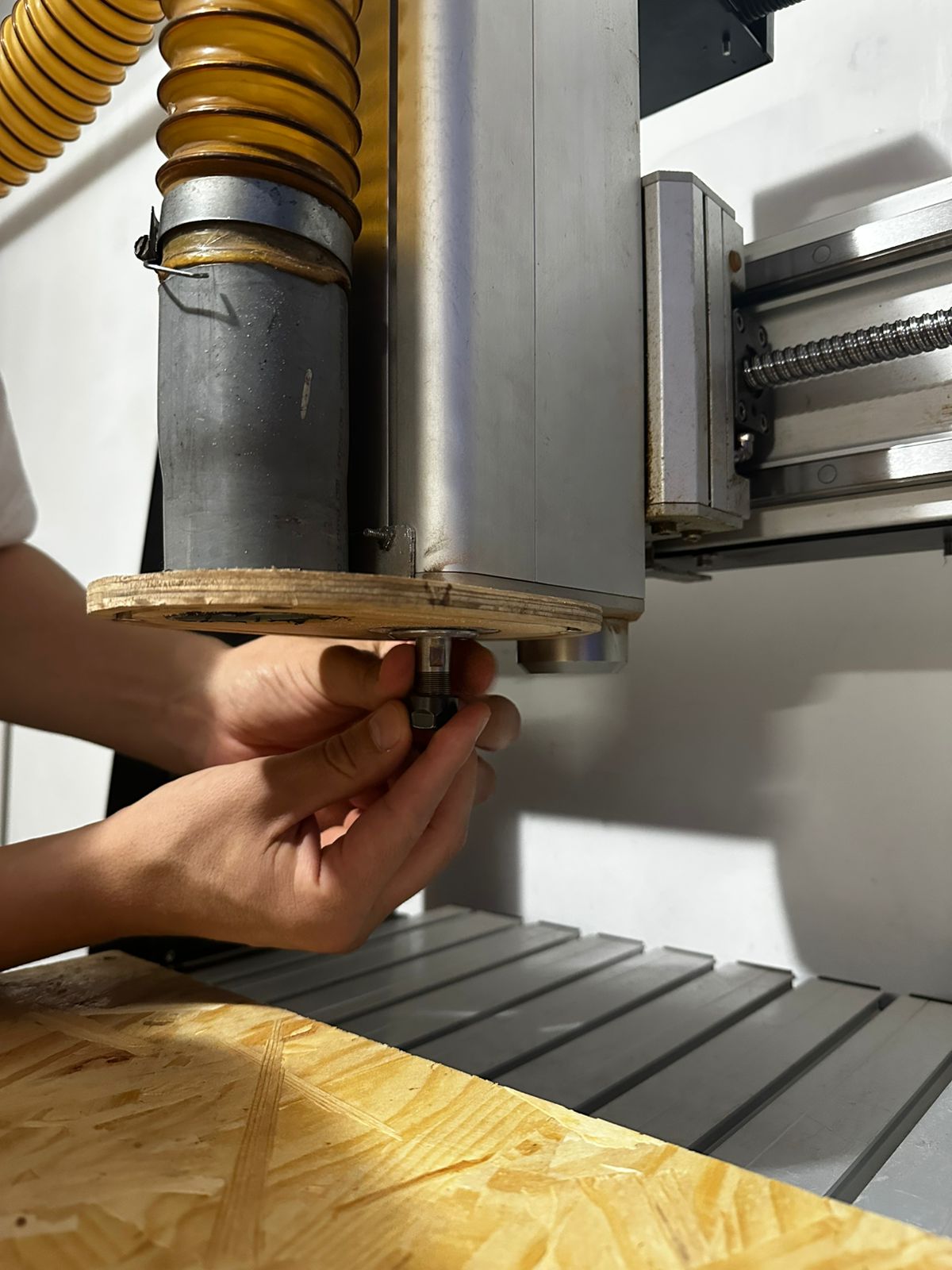
- The cutting tool is properly installed and tightened in the collet.
- The correct work origin or zero point has been defined.
- The correct toolpath and machining parameters have been loaded.
- A simulation or dry run has been reviewed to prevent collisions.
In case of an unexpected issue, the emergency stop button must be used immediately to halt machine operation.
2. Machine Used
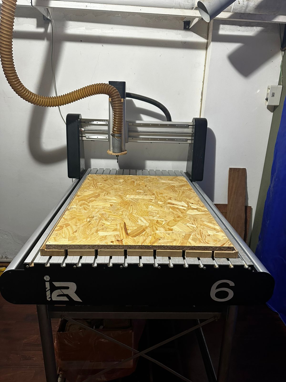
The laboratory is equipped with an i2R CNC router, a numerically controlled machine designed for machining sheet materials commonly used in digital fabrication processes.
This type of machine is especially suitable for cutting and milling board-based materials such as MDF, OSB, plywood, wood, and some plastics.
General Characteristics
- Approximate working area of 600 × 900 mm
- Three-axis motion system (X, Y, and Z)
- Flat working table for board fixation
- High-speed spindle for routing operations
- G-code based control system
- Compatibility with different cutting tools
- Dust extraction system for chip and dust removal
Compatible Materials
- MDF
- OSB
- Plywood
- Natural wood
- Acrylic and soft plastics
3. Cutting Tools
The machining result depends strongly on the type of cutting tool used. In CNC routing, different end mills can be selected according to the material, the type of operation, and the desired surface quality.
The most common tools used in this process include:
- Flat end mill: mainly used for profile cutting and pocketing operations.
- Ball nose end mill: commonly used for curved or 3D surfaces.
- Upcut bit: removes chips upward and improves chip evacuation.
- Downcut bit: provides a cleaner top surface finish.
- Compression bit: combines upcut and downcut behavior to improve finish on both sides of the board.
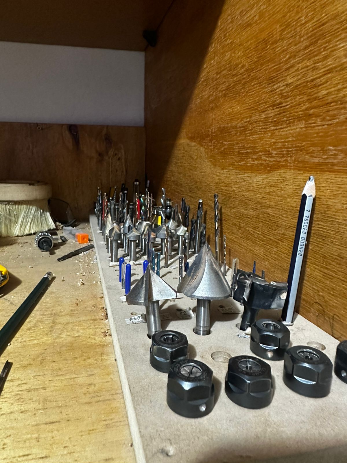
The most relevant tool characteristics include diameter, number of flutes, cutting direction, and material type.
4. CAM Workflow and Software Configuration
During this stage, Autodesk Fusion 360 (Manufacture workspace) was used to generate toolpaths and prepare the file for CNC machining. The workflow followed a structured sequence from setup definition to G-code generation and machine execution.
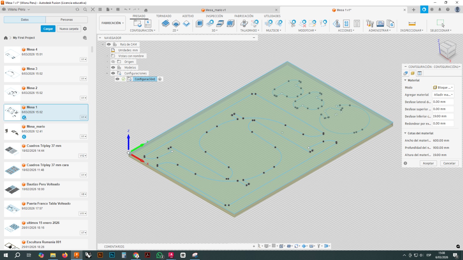
a. Setup Definition
The work environment was configured by defining the stock material (600 × 900 mm) and setting the coordinate origin. The origin was placed at a corner of the material to facilitate alignment with the CNC machine.
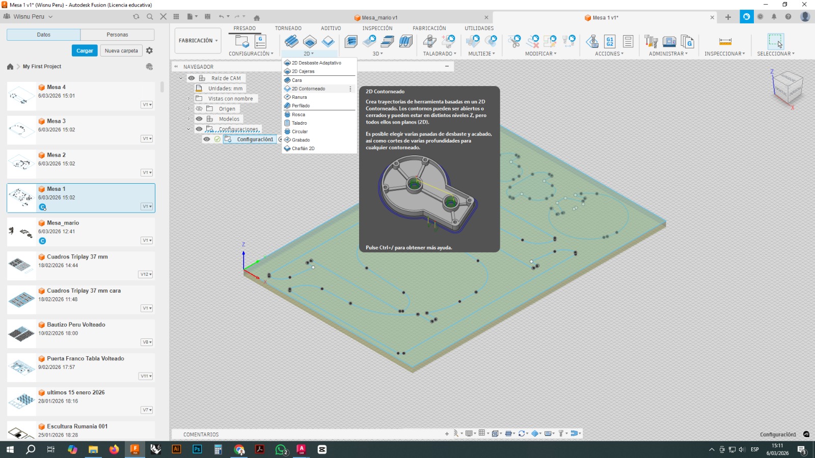
b. Machining Strategy Selection
A 2D Contour operation was selected to machine the profiles. This strategy is suitable for cutting both internal and external contours in flat geometries.
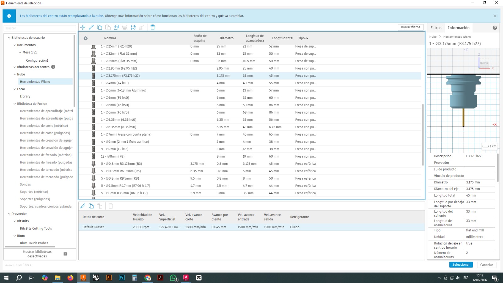
c. Tool Selection
A 3.175 mm (1/8”) flat end mill was selected. Parameters such as spindle speed, feedrate, and cutting conditions were defined to balance machining quality and efficiency.
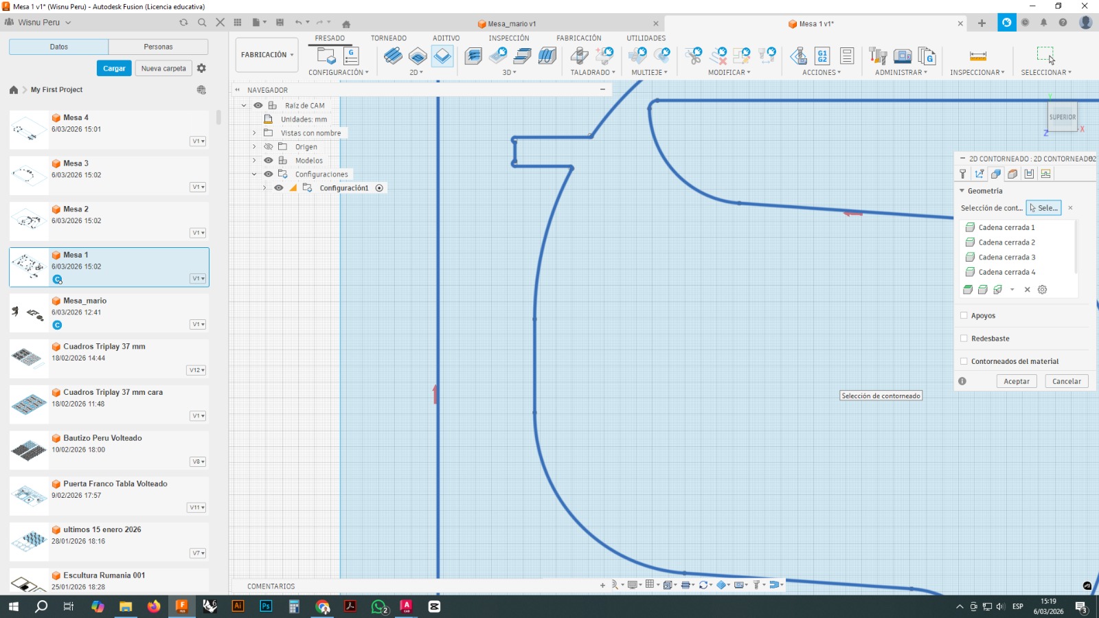
d. Geometry Definition
Contours were manually selected to ensure correct toolpath generation. Proper selection of closed profiles is critical to avoid machining errors.
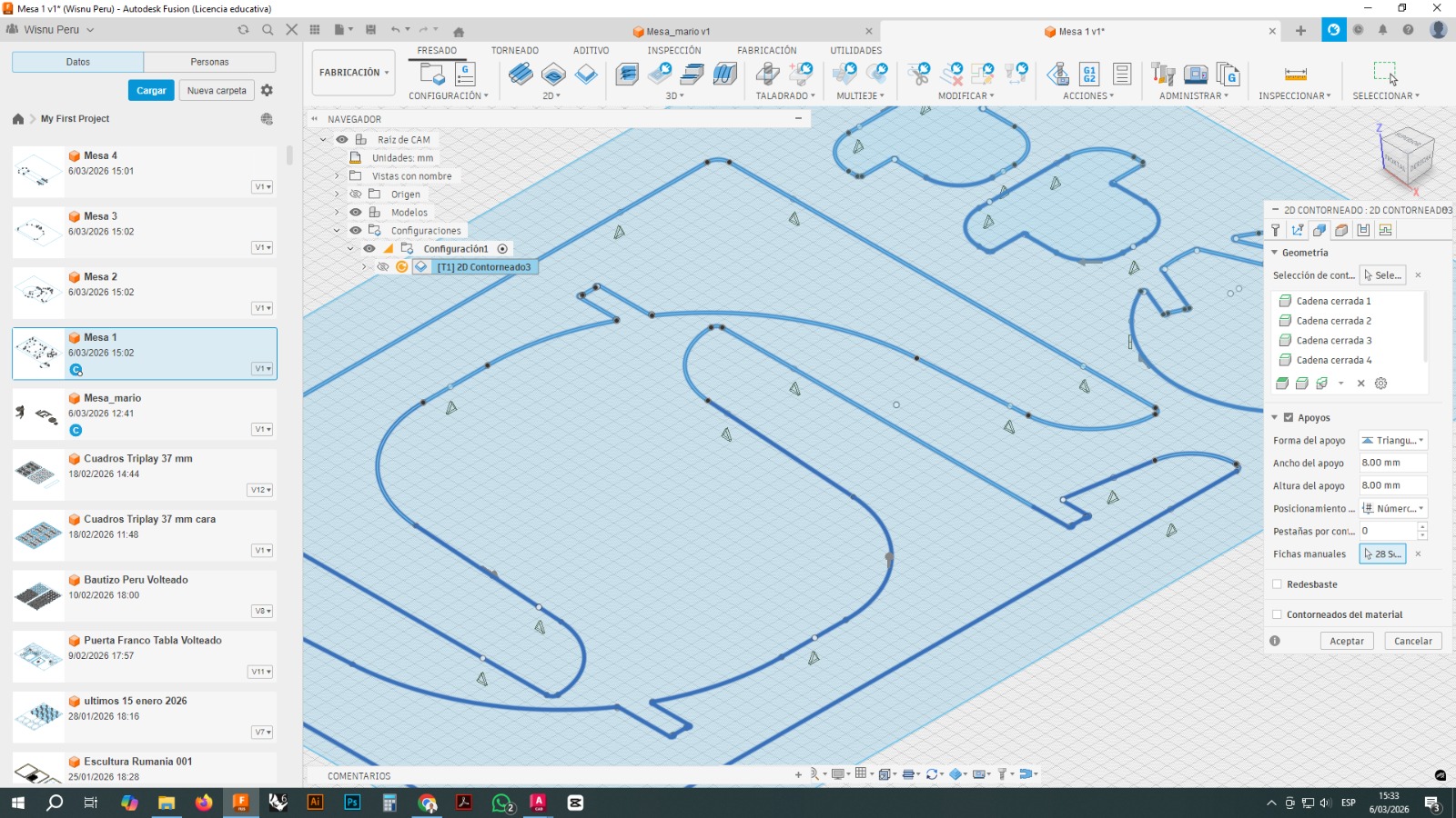
e. Toolpath Parameters and Validation
The toolpath was configured considering multiple key parameters to ensure a safe and efficient machining process. Multiple depth passes were defined to progressively remove material, reducing tool stress and improving cutting quality. Safety heights such as retract and clearance were set to prevent collisions during tool movements.
Additional parameters included radial stock to leave for finishing accuracy, smooth lead-in and lead-out movements to improve surface quality, and the use of tabs to keep parts fixed to the material during cutting.
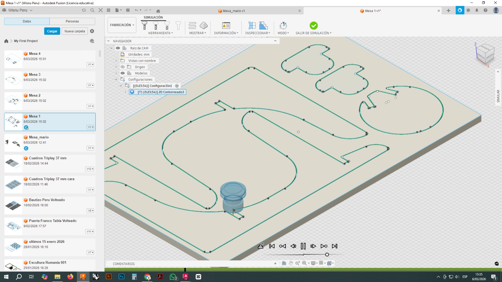
Finally, a full simulation was performed to validate toolpaths, verify cutting depths, and detect potential collisions before executing the machining process.
f. G-code Generation
The toolpaths were exported as a .nc file (G-code), containing all the instructions required by the CNC machine.
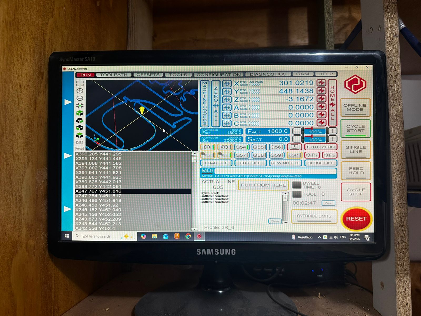
g. Machine Execution (UCCNC)
The G-code file was loaded into UCCNC software, which controls the CNC machine. This interface allows real-time monitoring of tool movement, spindle control, and execution of the machining process.
5. Machining Parameters
Machining parameters determine the quality, precision, and safety of the process. Correct parameter selection is essential for obtaining accurate cuts and avoiding tool or material damage.
The main parameters considered were:
- Spindle speed (RPM): rotational speed of the cutting tool.
- Feed rate: horizontal speed of the tool during cutting.
- Plunge rate: vertical entry speed into the material.
- Depth of cut: amount of material removed per pass.
- Step-over: lateral distance between adjacent passes.
- Tool diameter: directly affects the level of detail and cut width.
Incorrect settings may result in burning, poor surface quality, tool breakage, or dimensional inaccuracies.
6. Cutting Strategies
Different cutting strategies can be applied depending on the geometry of the part and the machining objective.
The main strategies considered in this characterization were:
- 2D profile cutting: used to cut the external or internal contour of a part.
- Pocketing: used to remove material from internal areas.
- Drilling: used for circular holes.
- Adaptive clearing: used for efficient material removal in more advanced operations.
Additional factors such as the use of tabs, operation order, and cutting direction must also be considered to ensure that the part remains stable and that the machining process is safe and accurate.
Reflection
This characterization helped us understand that CNC machining is not only about sending a file to a machine. Instead, it requires a clear understanding of the relationship between material properties, tool selection, machining parameters, and cutting strategies.
It also showed that even small errors in setup or file preparation can significantly affect the final result. For that reason, understanding the full workflow is essential before carrying out any machining operation.