
Week 05 | 3D Scanning and Printing
Week Description
This week focused on understanding additive manufacturing and digital capture technologies through hands-on experimentation. The process involved designing and fabricating 3D printed components, exploring material behavior, and evaluating how post-processing techniques can enhance form and functionality.
Group Assignment
This week's group assignment consisted of testing the design rules of the 3D printers available in the laboratory. The objective was to characterize the printing capabilities of the machines by analyzing parameters such as overhangs, bridging, tolerances, dimensional accuracy and fine detail reproduction.
These tests were performed using a calibration model and printed on the Bambu Lab A1 printer in order to better understand the limitations and performance of the equipment.
The complete documentation of the group work can be found in the following page:
Group assignment documentation
Individual Assignment
By integrating digital modeling, slicing strategies, and thermal shaping, the work explored how 3D printing can enable organic geometries and expressive forms. Additionally, this week introduces 3D scanning as a method for digitizing physical objects and expanding the workflow between physical and digital environments.
3D Printing Process
1. Design Objective
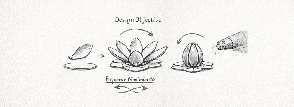
The goal was to develop modular 3D-printed petals that could be assembled onto a laser-cut base, allowing the exploration of formal variations and visual behavior by simulating opening and closing movements.
The design aimed to take advantage of additive manufacturing to create organic geometries that would be difficult to produce using subtractive methods.
2. 3D Modeling
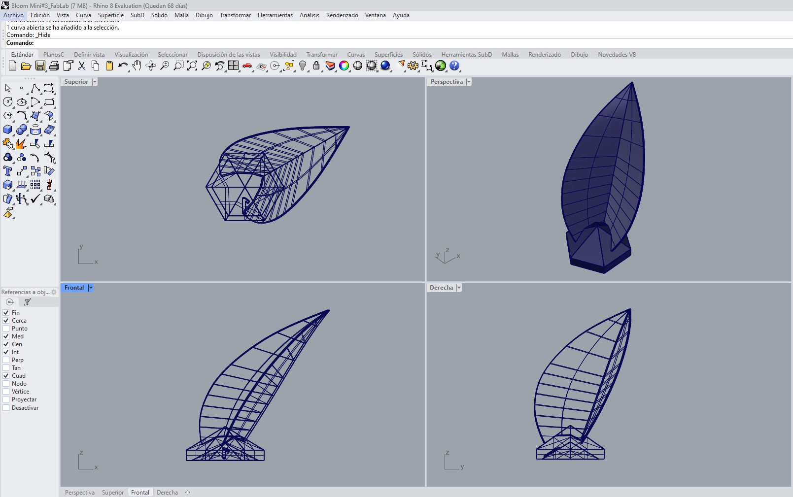
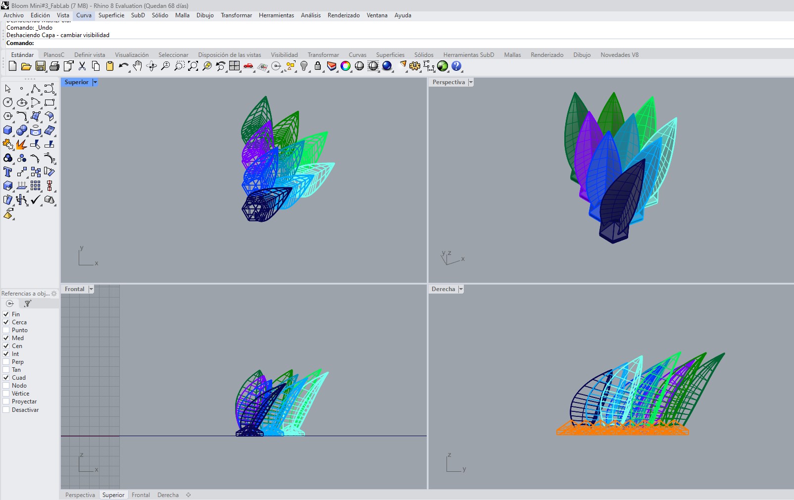
The 3D modeling of the system was developed in Rhinoceros, considering not only the final appearance of the flower, but also its fabrication process, assembly logic, and behavior after thermal forming.
The design is composed of two main elements: a modular hexagonal base and the petals. These were modeled as independent but integrated components within a radial and modular system.
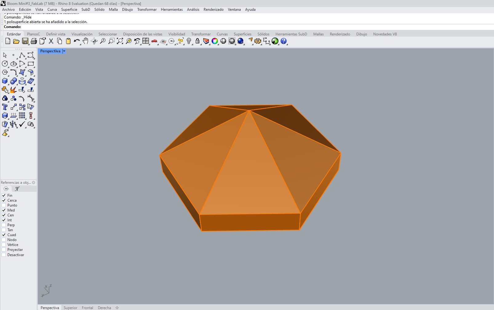
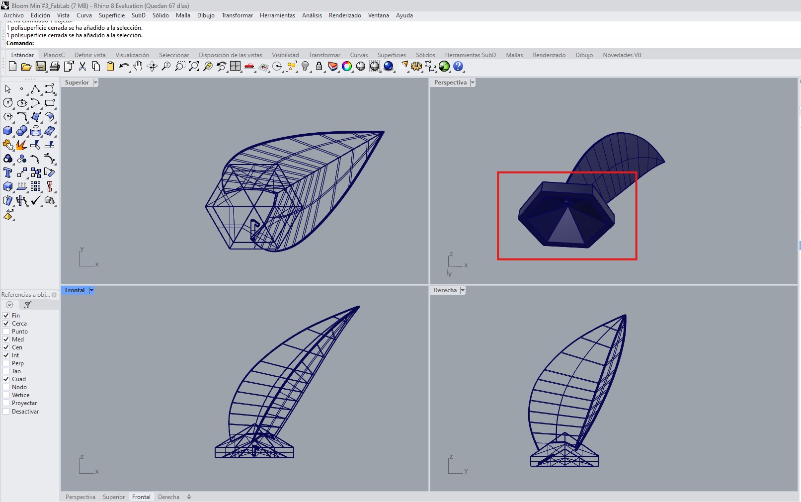
2.1. Hexagonal Base Design
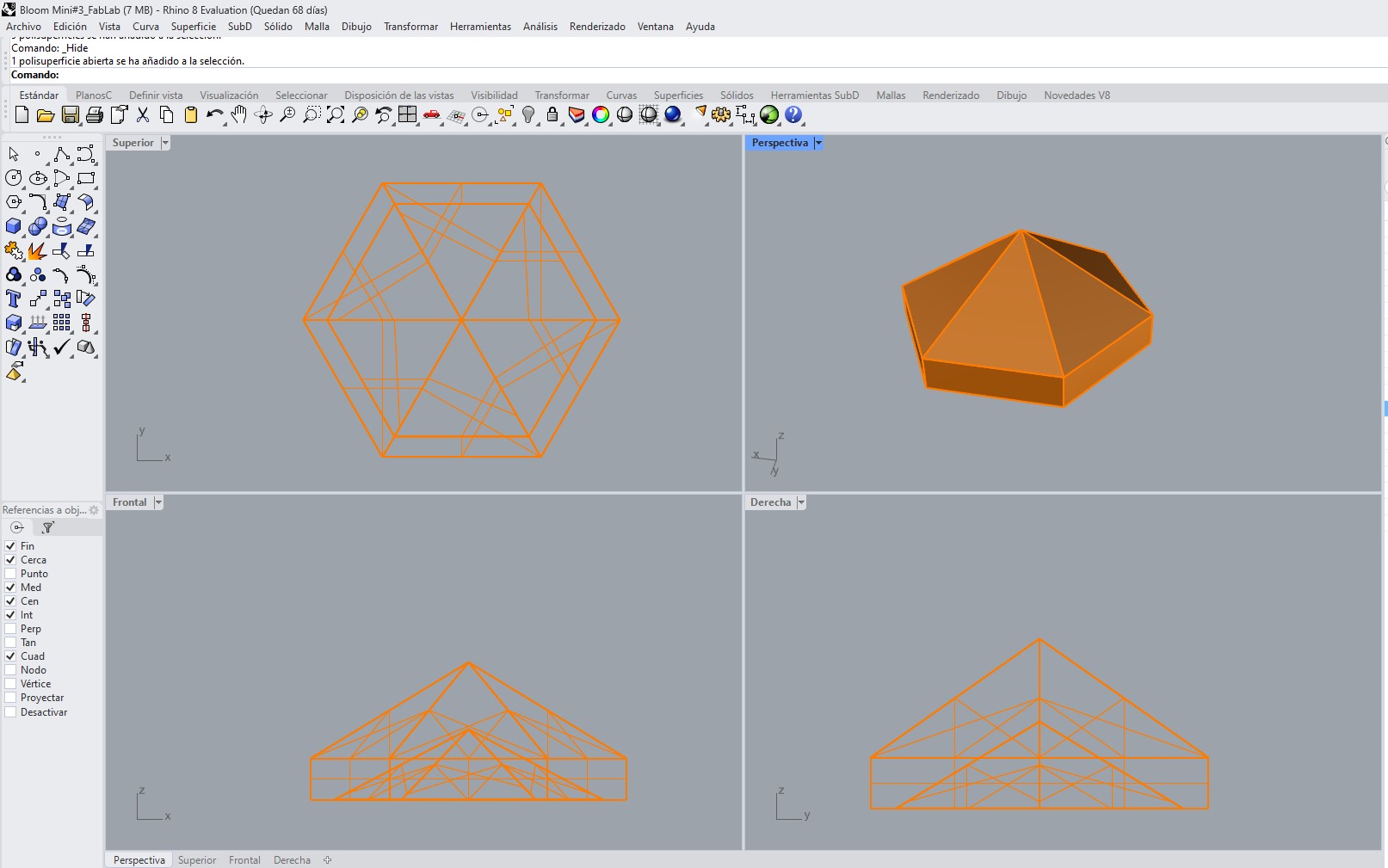
As a starting point, a hexagonal base was designed to support and organize the entire structure. This base acts as the main organizing element of the system, allowing the correct distribution and positioning of the petals within a radial configuration.
Each hexagonal module was numbered, which made it easier to identify the position of each part during assembly. This numbering system was especially important because it helped maintain order within a complex geometry composed of multiple repeated elements.
Instead of using a completely flat base, each module was designed with a cavity on its lower side. This design decision served two main purposes:
- to improve how the piece sits on the wooden base, providing better support and stability,
- to create a space where adhesive could be applied during assembly, improving the fixation of the parts.
In this way, the base was not only used as a geometric organizer, but also as a functional element that responds to real assembly requirements.
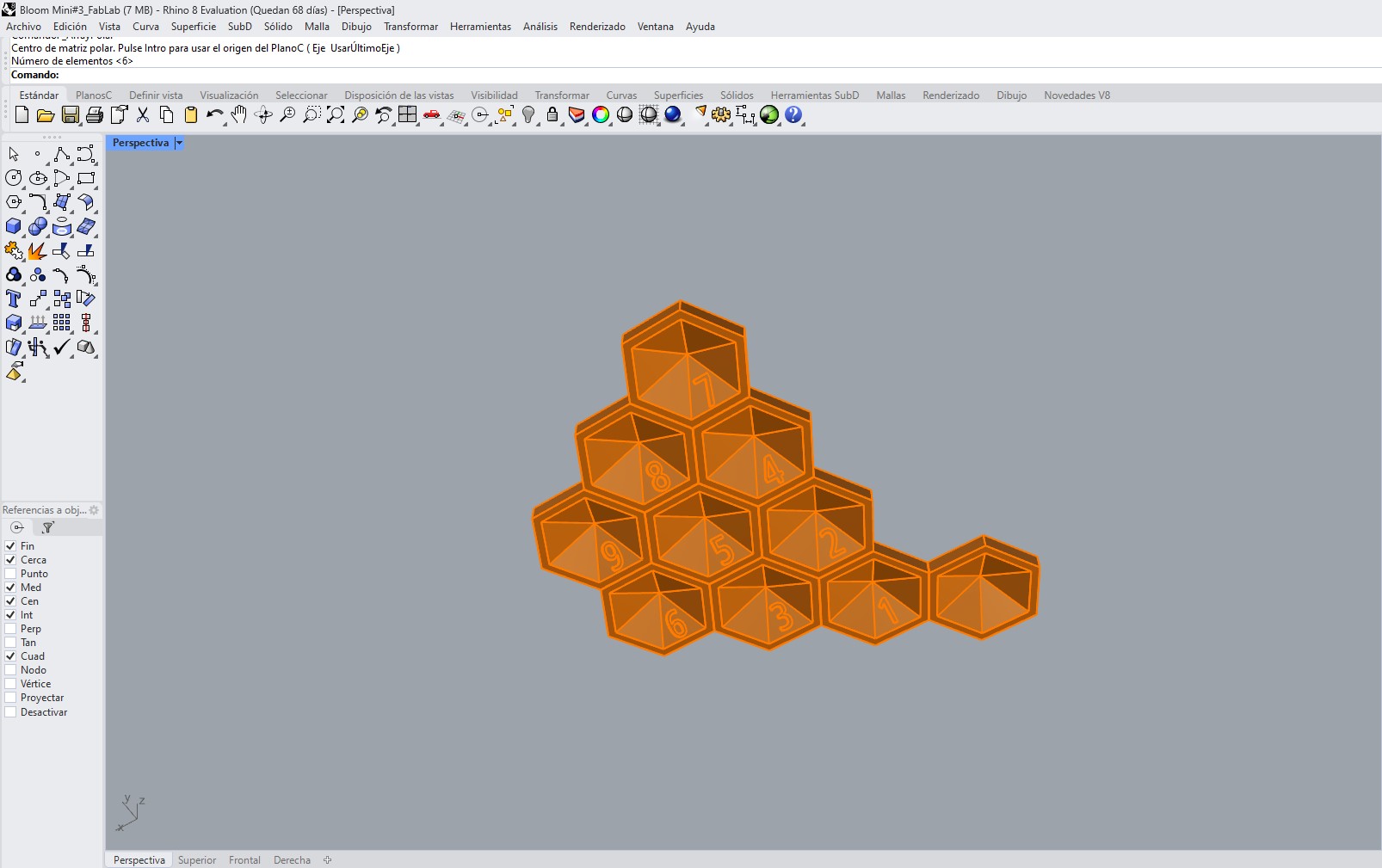
2.2. Petal Modeling
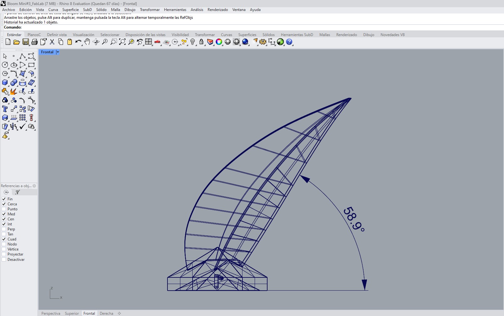
The petals were modeled using a surface-based workflow in Rhinoceros. Their geometry was generated through a two-rail sweep operation, which allowed precise control of both the profile and the overall transition of the surface.
The intention was to obtain a shape similar to a leaf, with smooth and continuous curves, so that after printing it could be thermally deformed into a more organic final form.
Rather than modeling the final deformed shape directly, the petal was designed as an intermediate geometry optimized for both fabrication and post-forming.
a.Fabrication-Oriented Design Considerations
Several design decisions were made specifically in response to the constraints of FDM 3D printing:
- Inclination angle (~60°): The petal body was designed with an approximate inclination of 60°, which allowed it to be printed without the need for support structures. This reduced post-processing and improved the surface quality.
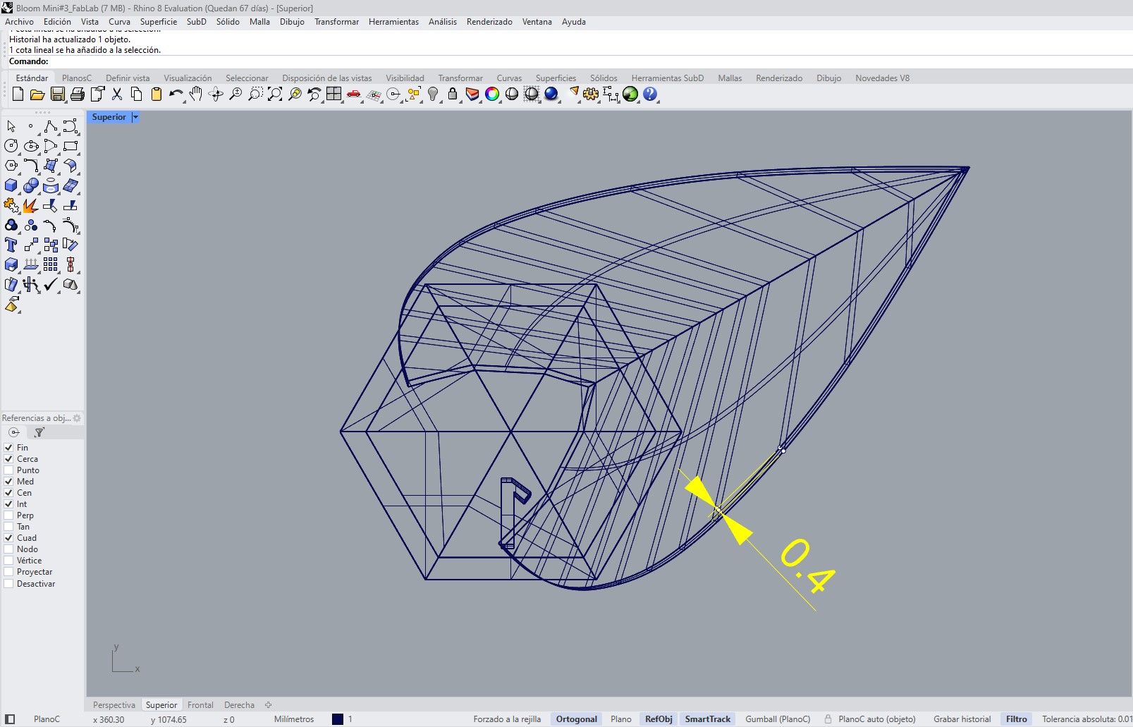
- Thickness (0.4 mm): The petal was given a thickness of 0.4 mm, which was the minimum value that still allowed the shape to print correctly while also remaining thin enough to be deformed with heat afterward.
- Leaf-like geometry: The overall form was intentionally kept close to a leaf shape in order to support a more natural and organic deformation once heat was applied.
- Flat printing base: Each petal includes a flat base area to ensure good adhesion to the print bed and improve print stability.
b. Organization and Assembly Logic
Although all petals originated from the same base geometry, each one required a slightly different orientation within the radial system.
To manage this complexity, the design incorporated:
- numbering on the base of each piece,
- orientation control for each petal,
- and a direct relationship between each petal and its corresponding hexagonal module.
This organization made the assembly process clearer and reduced the possibility of errors when placing the parts into the final structure.
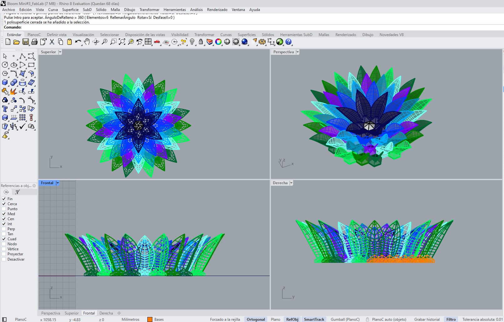
c. Replication and Radial Arrangement
Once the base petal geometry was defined, several tests were performed to replicate and distribute it in a radial arrangement.
This process included:
- duplicating the base module,
- rotating each petal according to its angular position,
- adjusting the orientation so that every element points toward the center,
- and controlling the spacing between pieces.
As a result, nine petal variations were generated and then repeated across six modules to complete the overall flower geometry.
The combination of a modular base and deformable printed petals made it possible to develop a system that integrates design, fabrication, and physical transformation into a single workflow.
3. File Preparation and Slicing
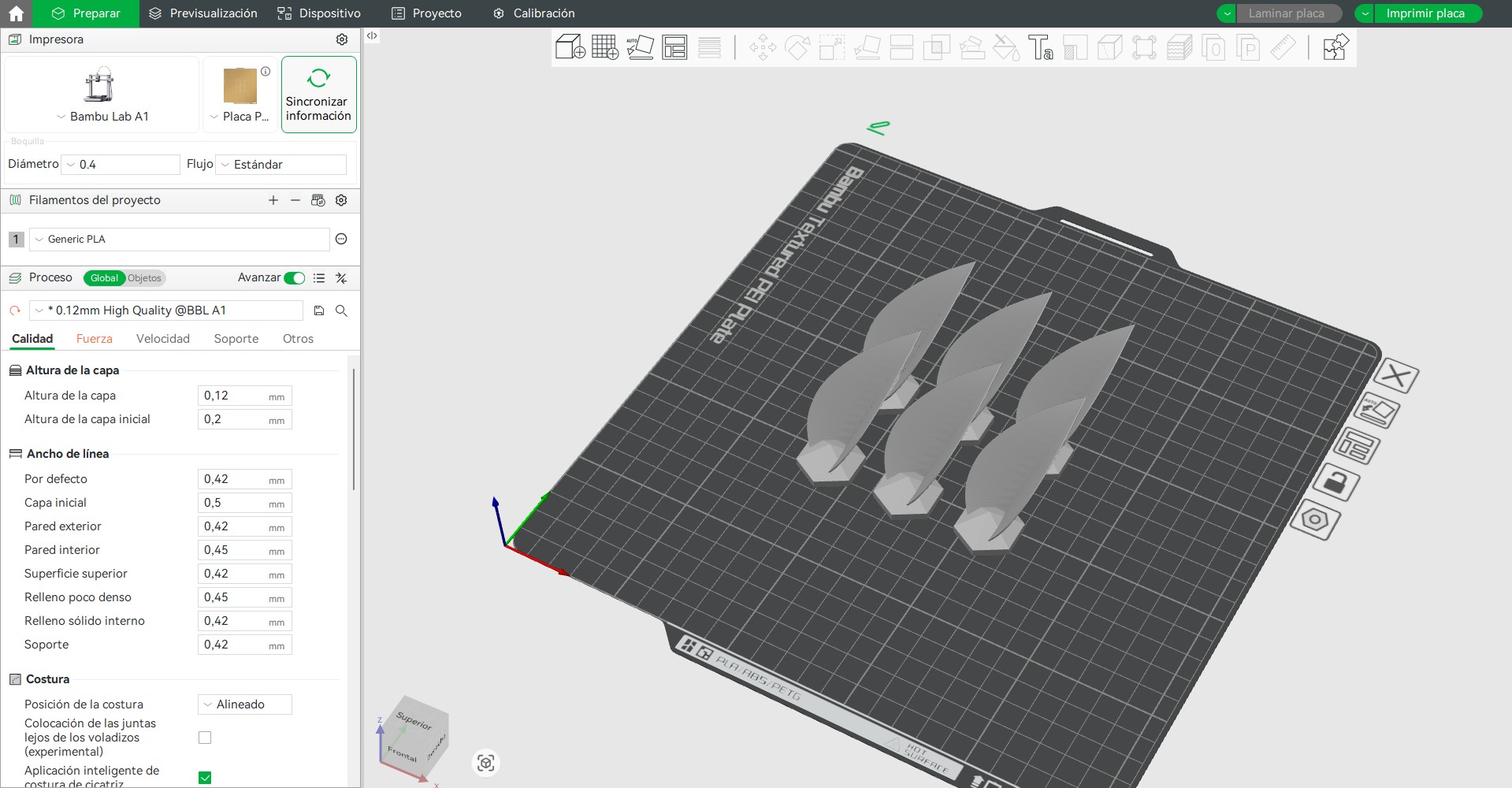
Once the 3D model was completed, it was exported in STL format and imported into Bambu Studio, the slicing software used to generate the printing toolpaths.
This stage is fundamental in the digital fabrication workflow, since it translates the 3D geometry into machine instructions that the printer executes layer by layer through G-code.
a. Model Import and Verification
After importing the STL file into Bambu Studio, an initial verification of the model was carried out to ensure that it was ready for fabrication. This included:
- checking the correct scale and real dimensions,
- reviewing the mesh for possible errors,
- and verifying the correct placement of the model on the print bed.
This step was important to avoid fabrication errors and to ensure that the printed piece matched the original design.
b. Print Organization Strategy
The complete flower system is composed of 9 different petal models, which are repeated to build the final geometry.
To optimize the fabrication process, the printing was organized as follows:
- 6 petals were printed per print bed
- each print group corresponded to one specific petal type
- and each petal type was repeated 6 times in order to complete the full flower
This strategy helped optimize the use of the print bed, reduce the total number of print jobs, and keep the production process organized by groups.
c. Orientation Strategy
Each petal was carefully oriented to maximize print stability and surface quality. The flat base of each piece was placed in direct contact with the print bed, improving adhesion and reducing the risk of print failure.
The orientation was also defined considering:
- minimizing supports,
- preserving surface quality on visible faces,
- and ensuring stability during printing.
d. Support Strategy
No supports were used during printing.
This was possible because the model was designed with an approximate 60° inclination angle, allowing the geometry to be self-supporting during the print.
Avoiding supports provided several advantages:
- reduced printing time
- better surface quality
- and no additional post-processing for support removal
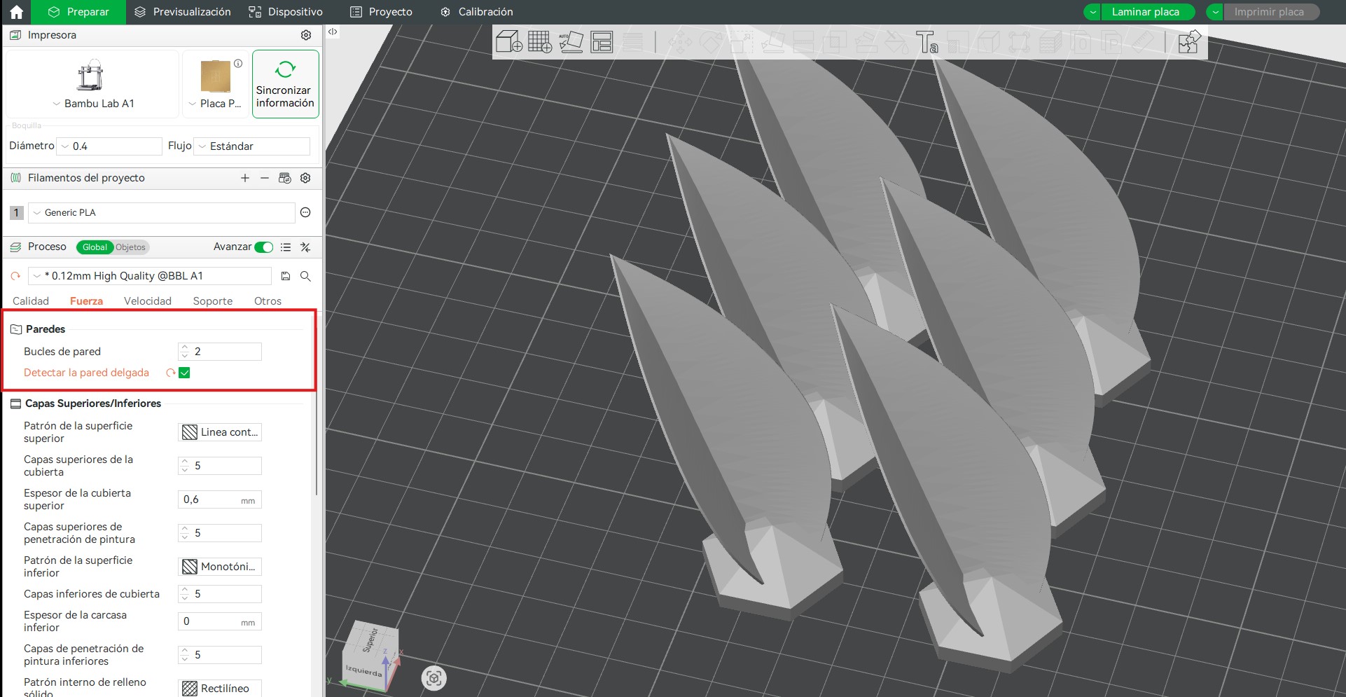
e. Printing Configuration
PLA was used as the printing material due to its stability and ease of printing.
The main parameters used were:
- Layer height: 0.12 mm
- Material: PLA
- Detect thin walls: enabled
The selected layer height of 0.12 mm improved surface quality and the definition of the curves, which was especially important for the organic geometry of the petals.
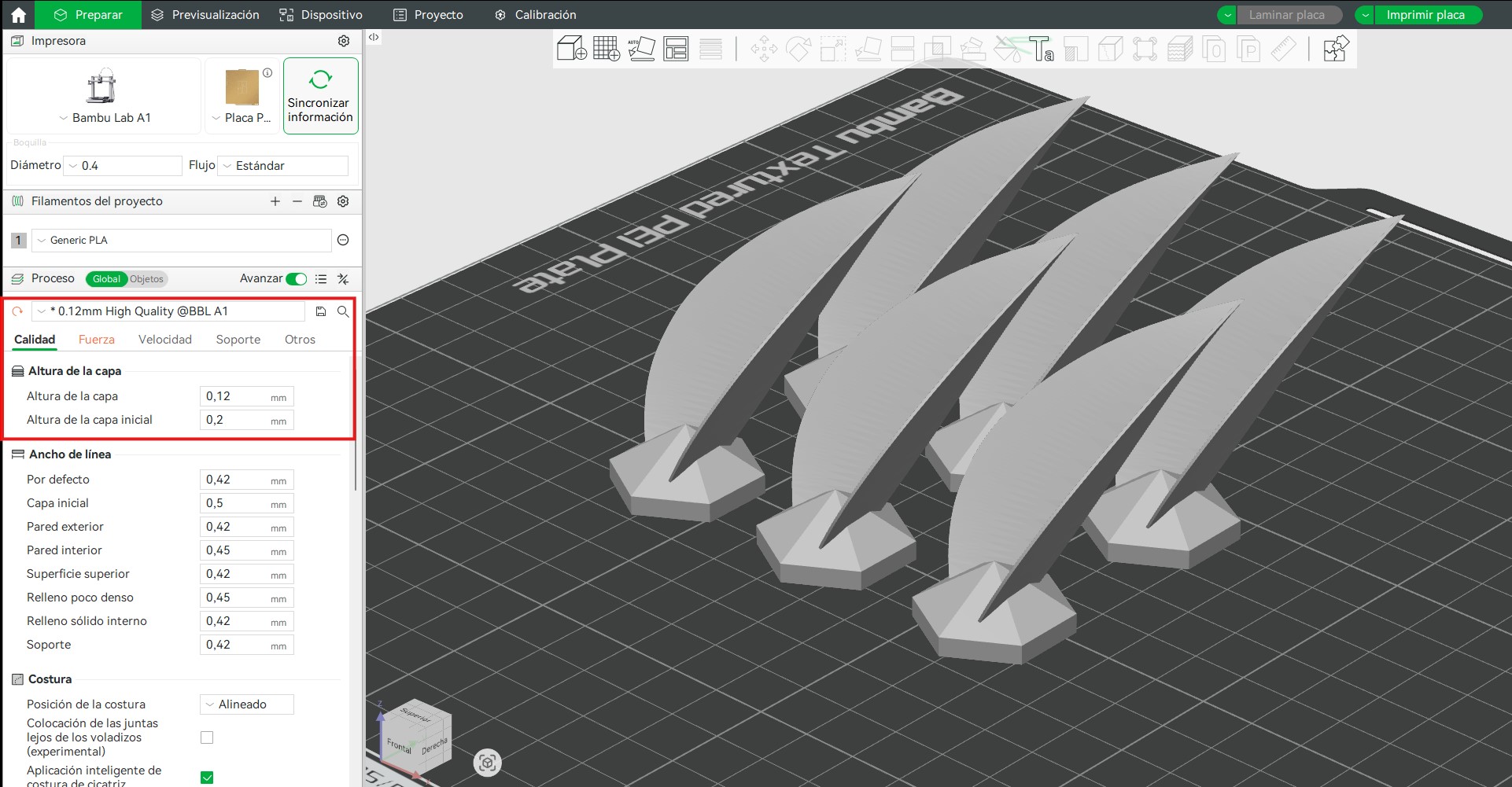
Enabling the detect thin walls option was essential because the petal thickness is approximately 0.4 mm. This setting allowed the slicer to generate proper toolpaths in these thin regions instead of ignoring or simplifying them.
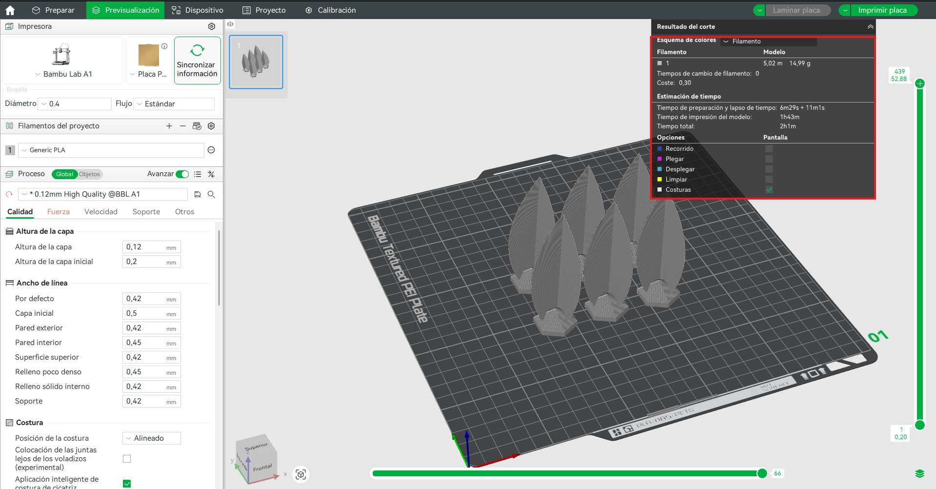
f. Toolpath Generation and Preview
Once the parameters were defined, the model was sliced and the preview mode was used to analyze:
- the layer-by-layer construction of the pieces,
- the nozzle movement paths,
- the continuity of extrusion,
- the estimated print time,
- and the material consumption.
Each group of 6 petals required approximately:
- Printing time: 2 hours
- Material usage: 17.17 g
This information was useful not only to validate the slicing process, but also to estimate the total production effort required for the complete flower.
g. Final Preparation
After validating the simulation, the file was prepared for printing. The generated G-code contained all the instructions needed by the printer, including movement, temperatures, speed, and extrusion control.
This ensured a controlled and repeatable fabrication process.
It also highlighted the importance of:
- organizing production in groups,
- adapting print settings to the geometry,
- and using advanced options such as thin wall detection when required by the design.
These decisions were essential for achieving a successful print of a complex system composed of multiple thin and repeated elements.
4. Printing Process
The parts were printed using a Bambu Lab A1, a high-precision FDM printer. This machine provides reliable and consistent results, allowing accurate reproduction of the designed geometry. The printer was configured to balance print quality and speed, ensuring good surface finish and dimensional accuracy while maintaining efficient production times. PLA filament was used as the printing material, due to its ease of use and stability during the printing process.
Printer specifications:
- Technology: FDM (Fused Deposition Modeling)
- Build volume: 256 × 256 × 256 mm
- Extrusion system: direct drive
- Bed leveling: automatic
- Maximum speed: up to 500 mm/s
- Material compatibility: PLA, PETG, TPU and more
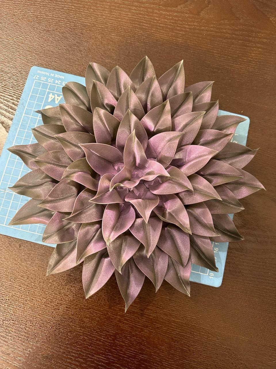
- Material used:Purple iridescent PLA
During printing, the first layers were monitored to ensure proper adhesion and extrusion stability. The parts printed successfully without deformation or defects.
6. Post-Processing and Assembly Preparation
After fabrication, each printed component was carefully positioned on the base to verify the correct orientation of every petal within the overall composition. This step was essential due to the variation in geometry and rotation of the petals, ensuring that each piece aligned properly according to the design logic.
Following this, a manual post-processing stage was carried out. Each part was cleaned using hand tools to remove small imperfections such as excess material, rough edges, or minor surface defects resulting from the printing process. This allowed for improved surface quality and ensured proper fitting between components during assembly.
These steps were critical to achieving a precise and stable final configuration, as well as maintaining the intended aesthetic and structural performance of the system.
5. Thermal Shaping and Formal Exploration
After printing, the petals were manually heat-formed to achieve more organic curvature.
This process allowed:
- reducing the perceived rigidity of the PLA
- exploring different opening angles
- simulating how the petals might open or close
- evaluating the expressive and visual behavior of the system
This stage was essential to approximate the dynamic character intended for the piece.
6. Assembly and Evaluation
The pieces were fixed using resin adhesive, ensuring structural stability. The engraved numbering system facilitated correct positioning on the laser-cut base.
Evaluation criteria:
- overall formal coherence
- structural stability
- surface quality
- expressive potential of the system
3D Scanning
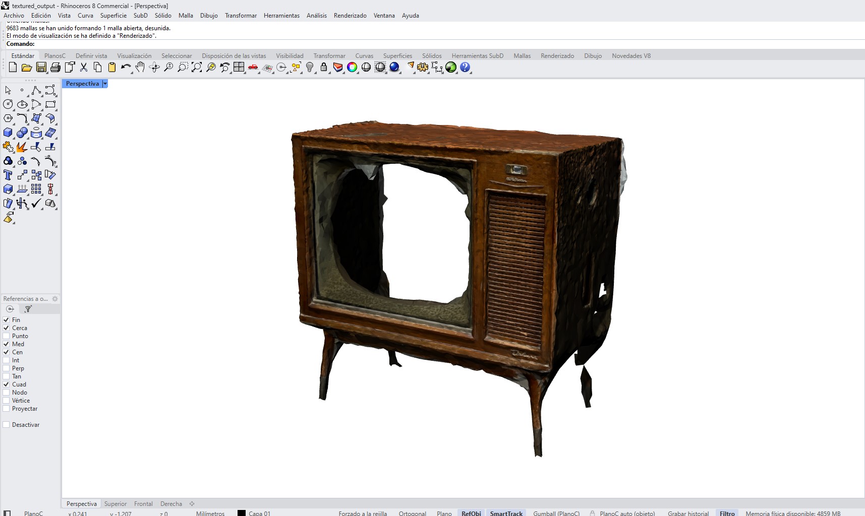
To explore object digitization, a damaged vintage television was scanned using the 3D Scanner App on a mobile device. The process relied on photogrammetric reconstruction, capturing multiple images from different viewpoints to generate a textured 3D mesh. Care was taken to ensure consistent lighting, minimize reflections, and maintain sufficient overlap between captures to improve alignment and reconstruction accuracy.
The object's irregular geometry and damaged surfaces introduced challenges, leading to noise, missing data, and artifacts in certain areas of the mesh. Nevertheless, the resulting model accurately represents the overall form and scale of the object, making it suitable for post-processing and mesh refinement.
a. Capture Process
The scan was performed by slowly moving around the object while maintaining a constant distance and steady motion. The app uses photogrammetry and depth capture to reconstruct geometry.
Methods explored:
- Point cloud capture to record spatial depth data.
- Mesh reconstruction to generate a triangulated surface and texture.
Key considerations during scanning:
- Capture multiple angles around the object.
- Maintain consistent lighting and avoid harsh shadows.
- Avoid rapid movements to reduce tracking errors.
- Ensure overlap between passes for better reconstruction.
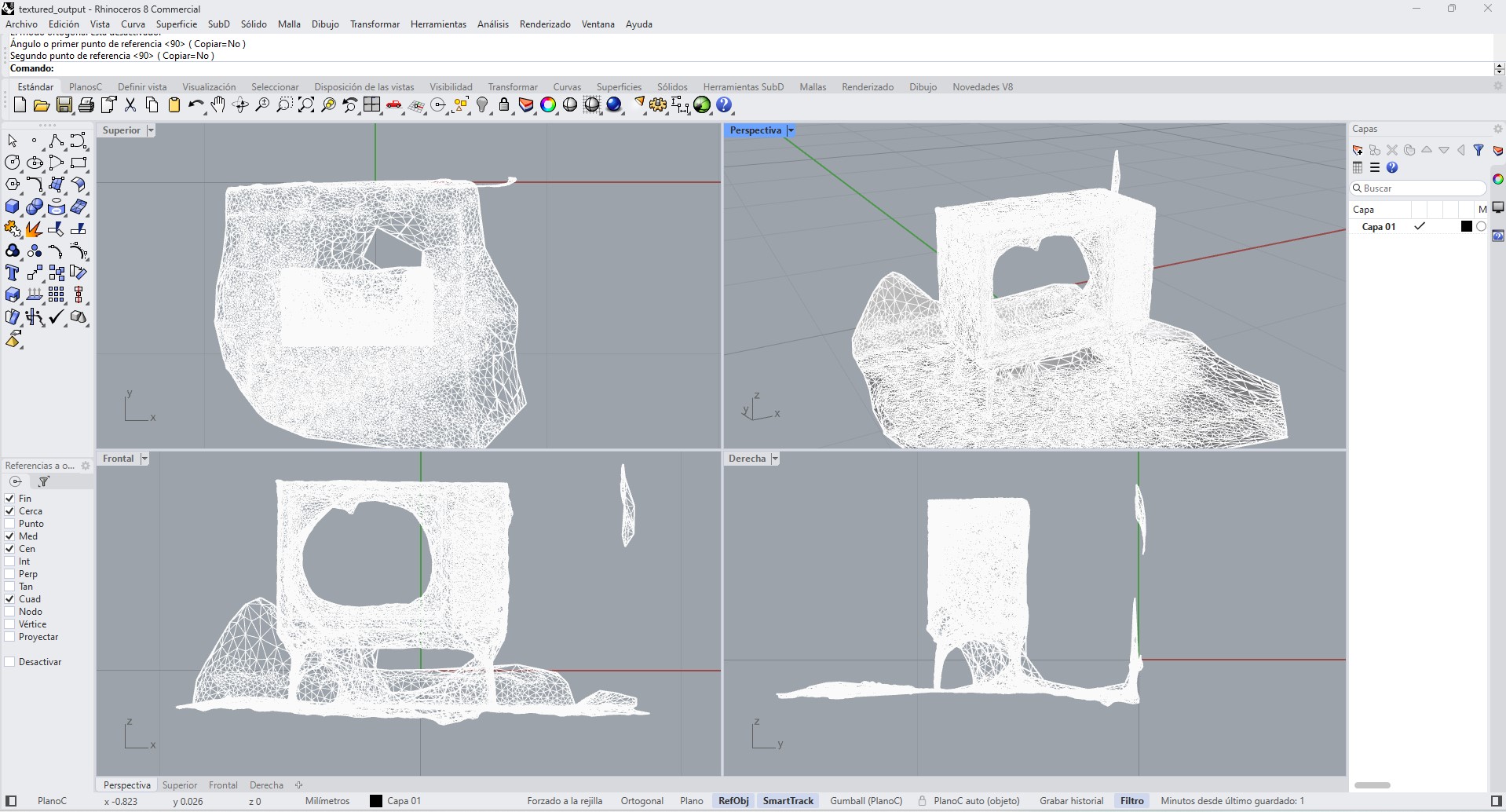
b. Scan Results
The scanning process resulted in a textured 3D mesh model of the object, capturing both its overall geometry and surface appearance. The reconstructed model shows the main structural features of the object; however, some areas present irregularities such as holes, noise, and incomplete regions, particularly in zones that were difficult to capture during scanning.
Despite these imperfections, the scan successfully represents the general shape and proportions of the object, making it suitable for further processing.
c. Mesh Export
After processing, the application generated a triangulated mesh model. The model was exported in OBJ format, including geometry and texture data.
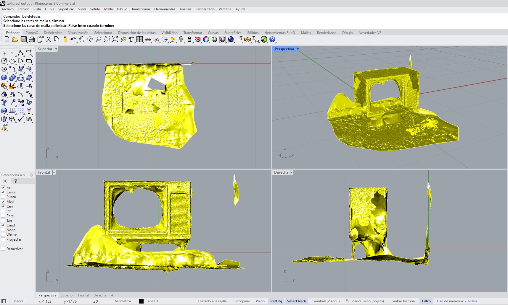
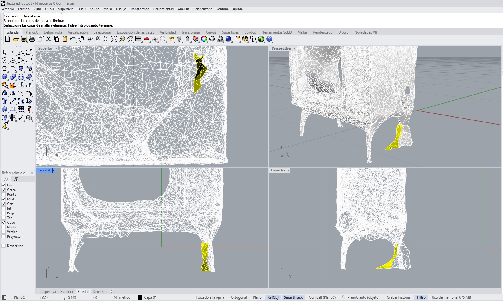
d. Mesh Cleaning in Rhino
The OBJ file was imported into Rhinoceros 8 for post-processing. The cleaning process included:
- Removing floating mesh fragments and noise.
- Deleting unwanted geometry from the surrounding environment.
- Closing visible holes where possible.
- Simplifying irregular areas to improve readability.
- Improving the overall mesh structure for visualization.
e. Evaluation
The scan captured the overall proportions and visual character of the object, but the result was not fully accurate due to limited resolution. Several issues were observed, including holes, missing surfaces, and noise in complex or reflective areas. Because of this, the model is more useful as a visual and dimensional reference rather than a fabrication-ready asset.
Learning Outcomes
- Identify the advantages and limitations of 3D printing
- Apply design methods and production processes to show understanding of 3D printing
- Demonstrate how scanning technology can be used to digitize object(s)