
Week 03 — Computer-Controlled Cutting
Learning Outcomes
- Evaluate and select 2D software
- Demonstrate and describe processes used in 2D design for cutting
- Identify and explain processes involved in using the laser cutter
- Develop, evaluate and construct a parametric construction kit
Group Assignment
This week's group assignment consisted of performing safety training and characterizing the laser cutter parameters, including focus, power, speed, kerf and joint clearance.
The complete documentation of the group work can be found in the following page:
Group assignment documentation
Individual assignments
This section documents the individual assignments for this week. The tasks included designing and laser cutting a parametric construction kit while considering the laser cutter kerf, and cutting a design using the vinyl cutter to understand the workflow from vector design to machine operation.
Part 1: Laser Cutting
This section documents the laser cutting process, including design preparation, machine setup, material testing, and final fabrication using the laser cutter.
1. Machine Review and Design Considerations
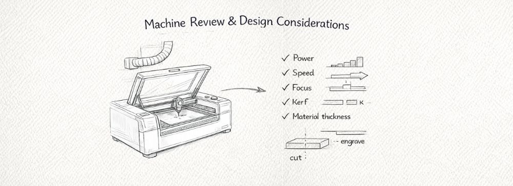
At the beginning of the process, a review of the laser cutter was conducted to understand its capabilities and limitations. This included checking the ventilation system, cleaning the working area, verifying the focus distance, and reviewing emergency and safety procedures before operation.
The work was carried out using a Trotec Speedy 300 laser cutter at the digital fabrication laboratory of PUCP. This professional CO2 laser system is designed for high-precision cutting and engraving and offers:
- Working area: 726 × 432 mm (29 x 17 pulgadas)
- Laser type / power: CO2, up to 80 W
- Maximum speed: up to 4.3 m/s
- Precision optics: suitable for detailed engraving and fine cuts
- Compatible materials: wood, MDF, cardboard, acrylic, leather, rubber, textiles, and more
- Safety: integrated exhaust and safety system for controlled operation
For the digital workflow, the geometry was initially developed in Rhinoceros. The 2D vectors were then exported to Adobe Illustrator for line organization, color coding, and scale verification. Finally, the file was prepared and sent to the laser cutter using CorelDRAW, which is the software interface used by the Trotec Speedy 300 to define cutting and engraving parameters.
Understanding the complete software-to-machine workflow was essential to ensure correct vector interpretation, proper layer assignment (cut vs. engrave), and accurate parameter configuration before fabrication.
Key design parameters considered before cutting:
- Material thickness consistency
- Kerf compensation
- Minimum feature size
- Corner behavior (sharp vs. filleted edges)
- Power and speed balance
- Vector preparation (closed paths, no duplicated lines)
Considering these factors was essential to ensure precise, clean, and safe cutting results.
2. Material Exploration
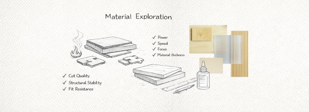
I experimented with two different materials: cardboard and MDF. Cardboard allowed quick prototyping and testing of joint tolerances due to its flexibility and low cost. MDF provided a more rigid and structural result, closer to the intended final application.
This comparison helped evaluate:
- Cut quality and edge finish
- Structural stability
- Fit resistance in press-fit joints
- Burn marks and surface behavior
3. 2D Design
In this stage, the 2D design of the pieces intended for laser cutting was developed. This process was approached from two complementary directions: first, a press-fit joint experiment aimed at understanding the relationship between slot tolerances and assembly behavior; and second, the development of the structural base for my personal project, where both cutting and engraving operations were integrated.
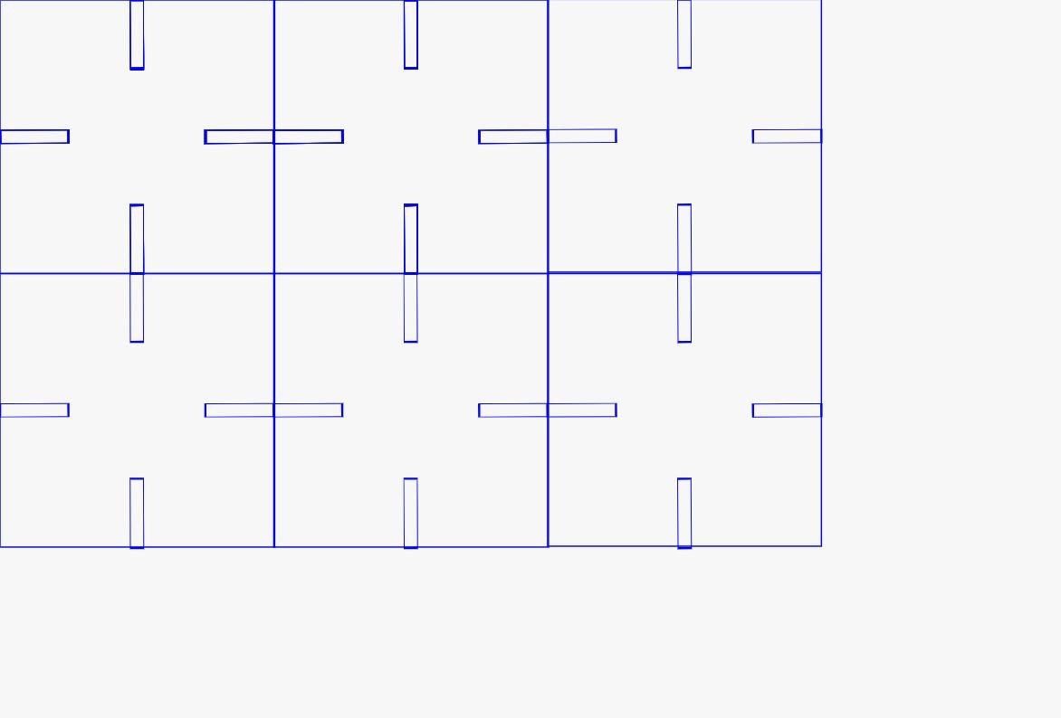
A. Press-Fit Joint Experiment
The first part of the process focused on designing a grid of pieces with multiple slot configurations in order to evaluate how different tolerances affect the fit between flat components. This experiment was specifically intended to understand how material thickness and laser kerf directly influence the quality of the joint.
Each slot was designed with slight dimensional variations, making it possible to test different fitting conditions. Through this process, three main behaviors could be observed:
- a loose fit, where the parts had excessive play,
- an appropriate fit, where friction allowed a stable assembly,
- and an overly tight fit, where assembly became difficult or forced the material.
This experiment was essential to determine the most suitable tolerance value, which could later be applied to the project design.
B. Development of the Project Base
In parallel, the base structure of my personal project was developed. This design was based on a modular hexagonal grid, which supports a radial and repetitive organization consistent with the overall concept of the project.
Unlike the press-fit test, this second design required two different machine operations:
- cutting, to define the geometry of the pieces,
- engraving / marking, to add numbers to each module and facilitate the assembly process.
The engraved numbers were especially important because even though many modules share the same general geometry, their orientation within the system varies. Numbering the pieces made the assembly process clearer and more organized.
Design in Rhinoceros
The initial geometry for both the press-fit experiment and the project base was developed in Rhinoceros. At this stage, the work focused on:
- creating the base geometries,
- defining slot positions and dimensions,
- organizing repeated modules in a grid or hexagonal arrangement,
- and preparing the layout of the pieces before fabrication.
Rhino was especially useful because it allowed accurate dimensional control, which is critical in digital fabrication processes where even small variations can affect the final physical result.
Once the geometry was defined, the necessary curves were extracted and prepared for 2D fabrication.
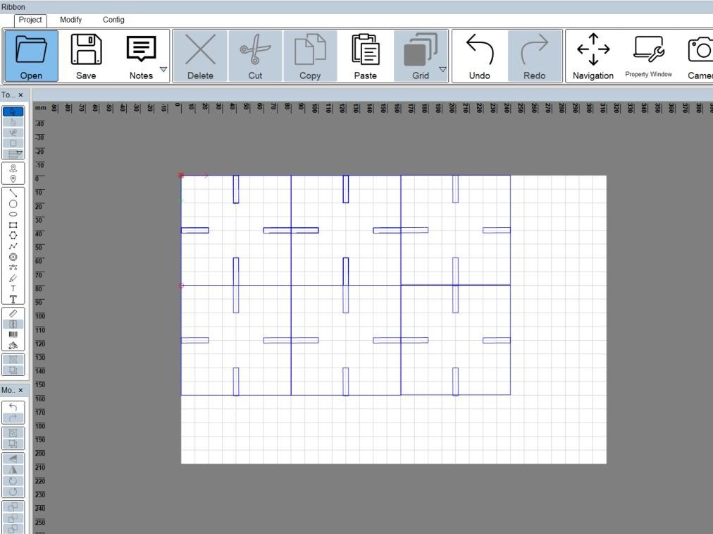
Vector Preparation in Adobe Illustrator
After the curves were generated in Rhino, they were exported to Adobe Illustrator for final preparation before laser cutting.
At this stage, several key adjustments were made to ensure the file could be interpreted correctly by the machine:
- removing duplicated or overlapping lines,
- checking that all contours were properly closed,
- organizing the geometry inside the working area,
- verifying scale and real dimensions.
In addition, a color coding system was applied to distinguish the machine operations:
- red lines were used for cutting,
- blue lines were used for engraving or marking.
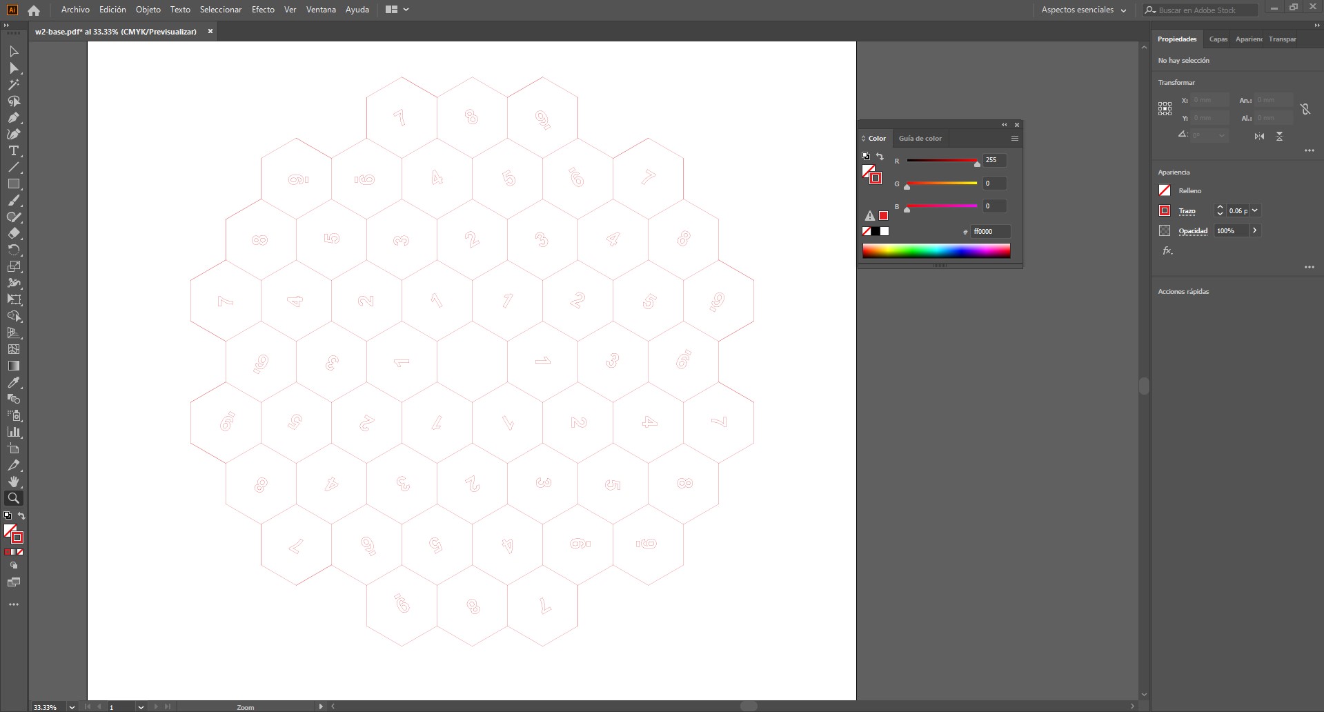
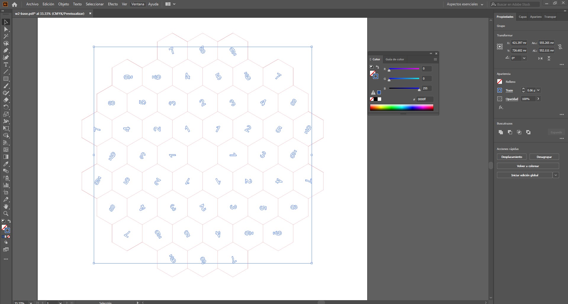
Both types of lines were assigned a very thin stroke, since the laser cutter interprets this kind of line as an executable path. In this case, the difference between operations was defined by color rather than by line thickness.
Integration with the Fabrication Process
The file prepared in Illustrator was then sent to the machine software, Trotec JobControl, where the assigned colors were translated into specific machine parameters such as power, speed, and frequency.
In this way, the 2D design did not only define the geometry of the parts, but also structured how the machine would execute the fabrication process.
4. Laser Cutting
Before starting the cutting process, a general inspection of the laser cutter was performed to ensure safe and optimal operation. This included verifying the cleanliness of the working bed, checking that the lens and mirrors were free of debris, and confirming that the extraction and filtration system was functioning properly. Once the machine was ready, the material was placed on the platform and properly aligned. The focus height was then calibrated to ensure accurate cutting and consistent energy distribution across the surface.
The file was prepared using the laser interface software Trotec JobControl, where the cutting parameters were assigned. In this workflow, different colors correspond to specific settings such as power, speed, and frequency, allowing the laser to distinguish between cutting and engraving operations.
After starting the job, the cutting process was continuously supervised to ensure the operation was proceeding correctly and safely, monitoring cut quality and watching for any signs of material burning or incomplete cuts. Once the cutting process finished, a short waiting period was observed before opening the machine and removing the material, allowing fumes to be extracted and the material to cool down safely.
Laser Parameters — MDF 2 mm (Trotec Speedy 30)
| Operation | Power | Speed | Frequency | Resolution | Passes | Air Assist |
|---|---|---|---|---|---|---|
| Vector Cutting | 80 – 90 % | 1.0 – 1.5 % | 1000 Hz | — | 1 | ON |
| Raster Engraving | 20 – 30 % | 80 – 100 % | — | 500 dpi | 1 | ON |
Recommended starting parameters. Final values may vary depending on MDF density, moisture content, and machine calibration.
Laser Parameters — Corrugated Cardboard (Trotec Speedy 30)
| Operation | Power | Speed | Frequency | Resolution | Passes | Air Assist |
|---|---|---|---|---|---|---|
| Vector Cutting | 40 – 55 % | 2.5 – 4.0 % | 1000 Hz | — | 1 | ON |
| Raster Engraving | 10 – 18 % | 90 – 100 % | — | 300 dpi | 1 | ON |
Starting parameters for corrugated cardboard. Adjust according to thickness, flute type, and burn sensitivity.
What I Learned
- Laser cutting requires careful consideration of material properties and kerf.
- Different materials respond differently to identical slot tolerances.
- Material testing significantly improves fabrication reliability.
- Design for fabrication must integrate machine limitations from the beginning.
Part 2: Vinyl Cutting
For this assignment, I worked with a vinyl cutter to produce shapes, text, and graphic elements on adhesive vinyl. The objective was to understand the complete workflow, from digital design to physical cutting, including material preparation, machine setup, and post-processing.
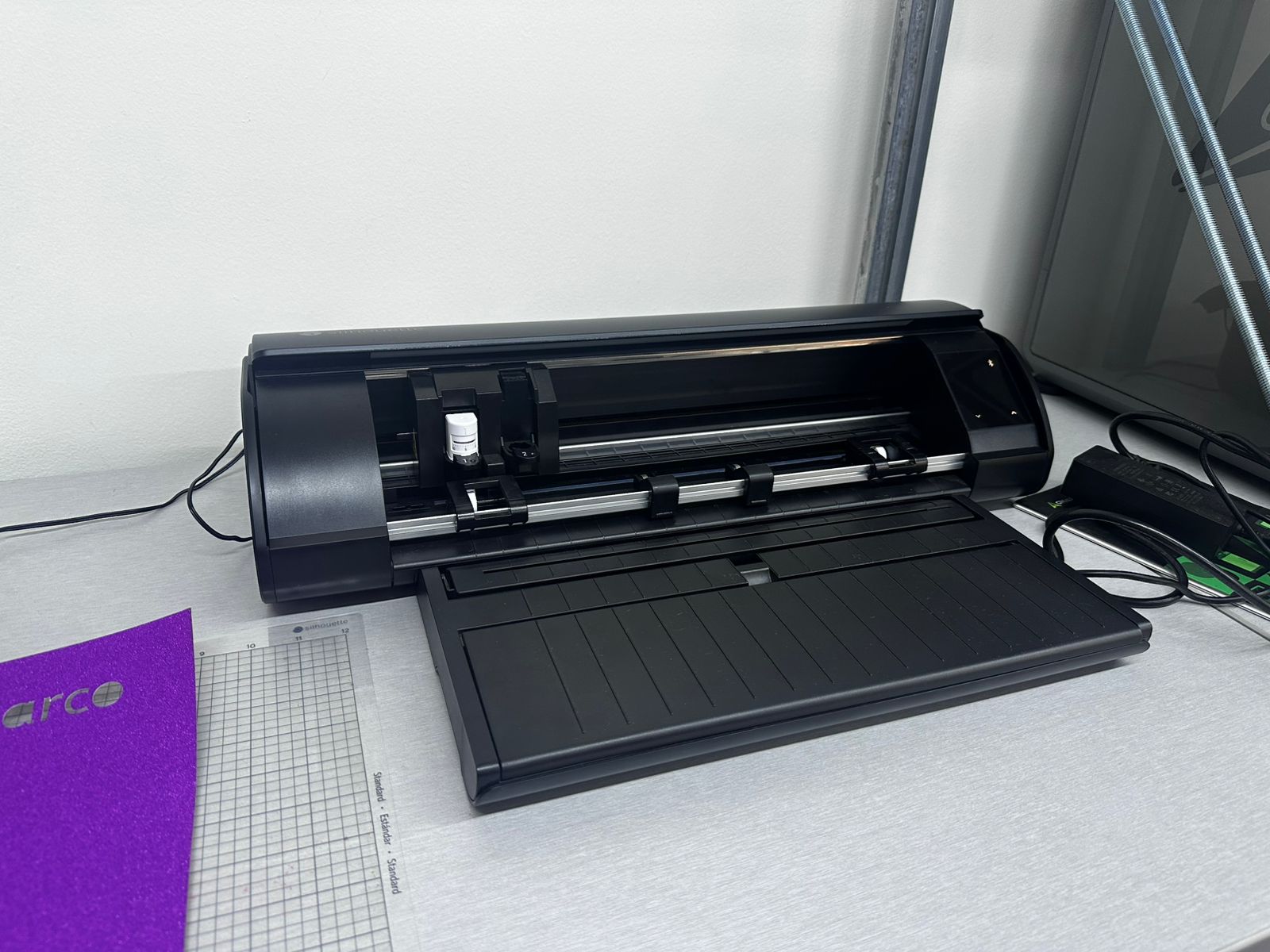
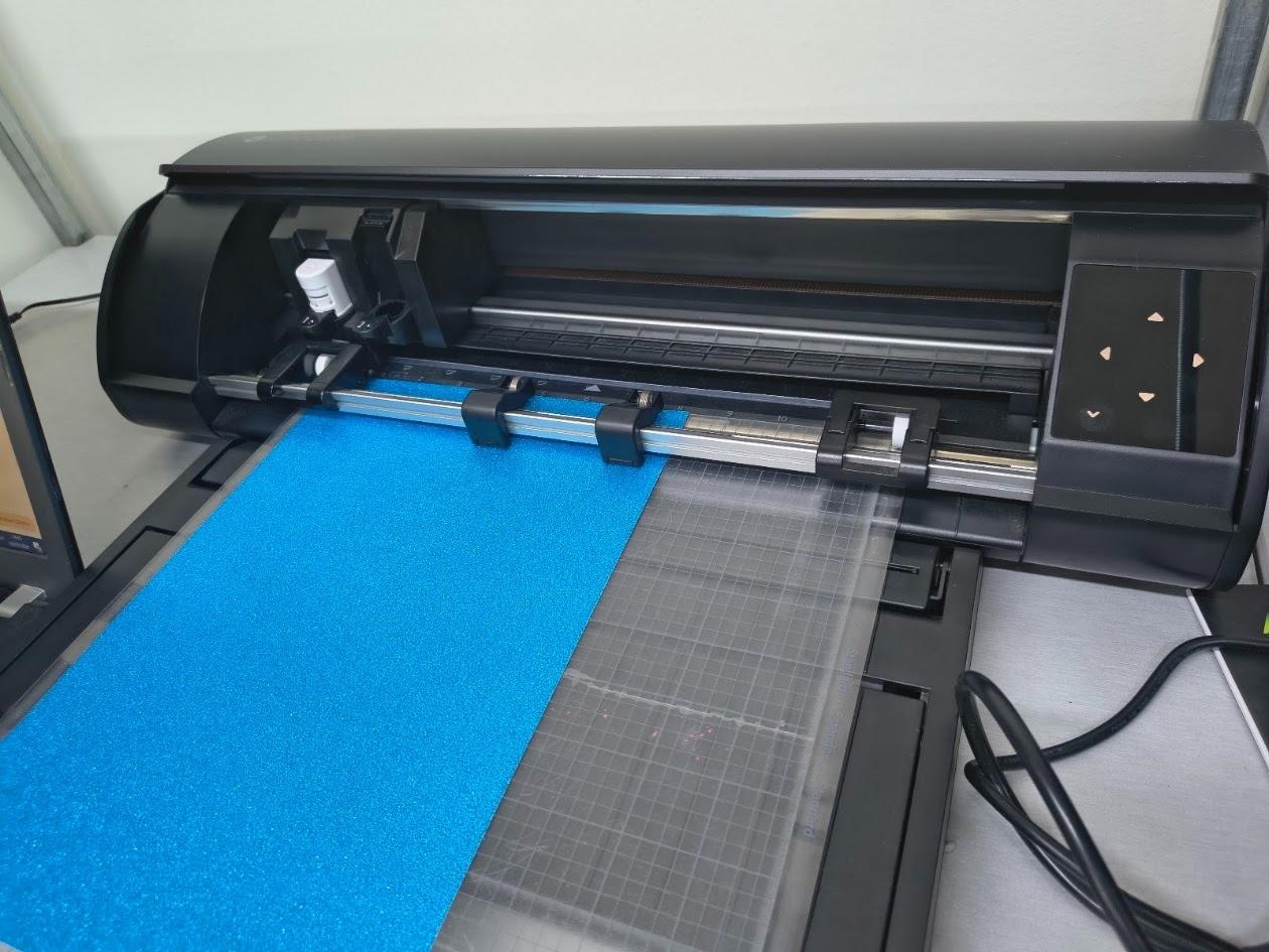
Machine
The machine used was a Silhouette vinyl cutter. This device operates using a small blade that moves along the X and Y axes,
while the material is fed forward and backward. This coordinated movement allows the machine to follow vector paths and cut
precise shapes on thin materials such as adhesive vinyl or sticker paper.
Material Exploration
During this process, different materials were explored to understand how the cutting behavior varies depending on thickness, flexibility, and surface properties.
- Adhesive vinyl: Used for cutting shapes and text, ideal for clean and flexible applications.
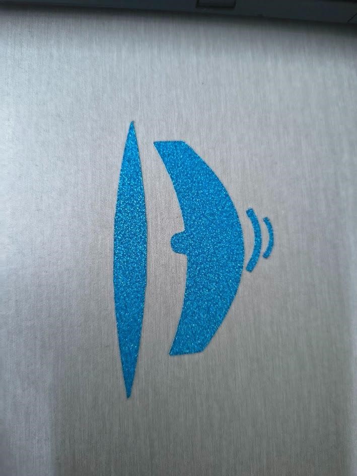
- Sticker paper: Used to print graphics (such as logos) and then cut them, combining printing and cutting processes.
This comparison allowed understanding how different materials respond to the cutting blade, especially in terms of edge quality, adhesion, and ease of removal.
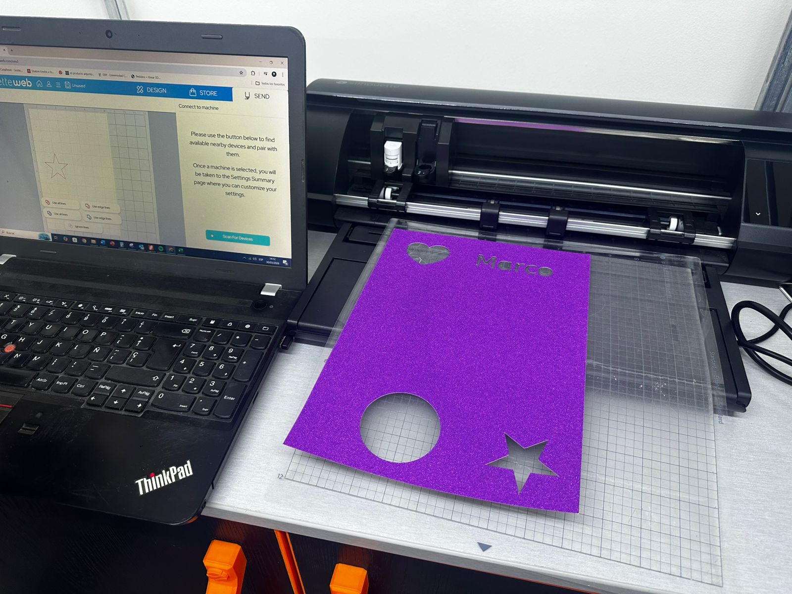
Design Preparation
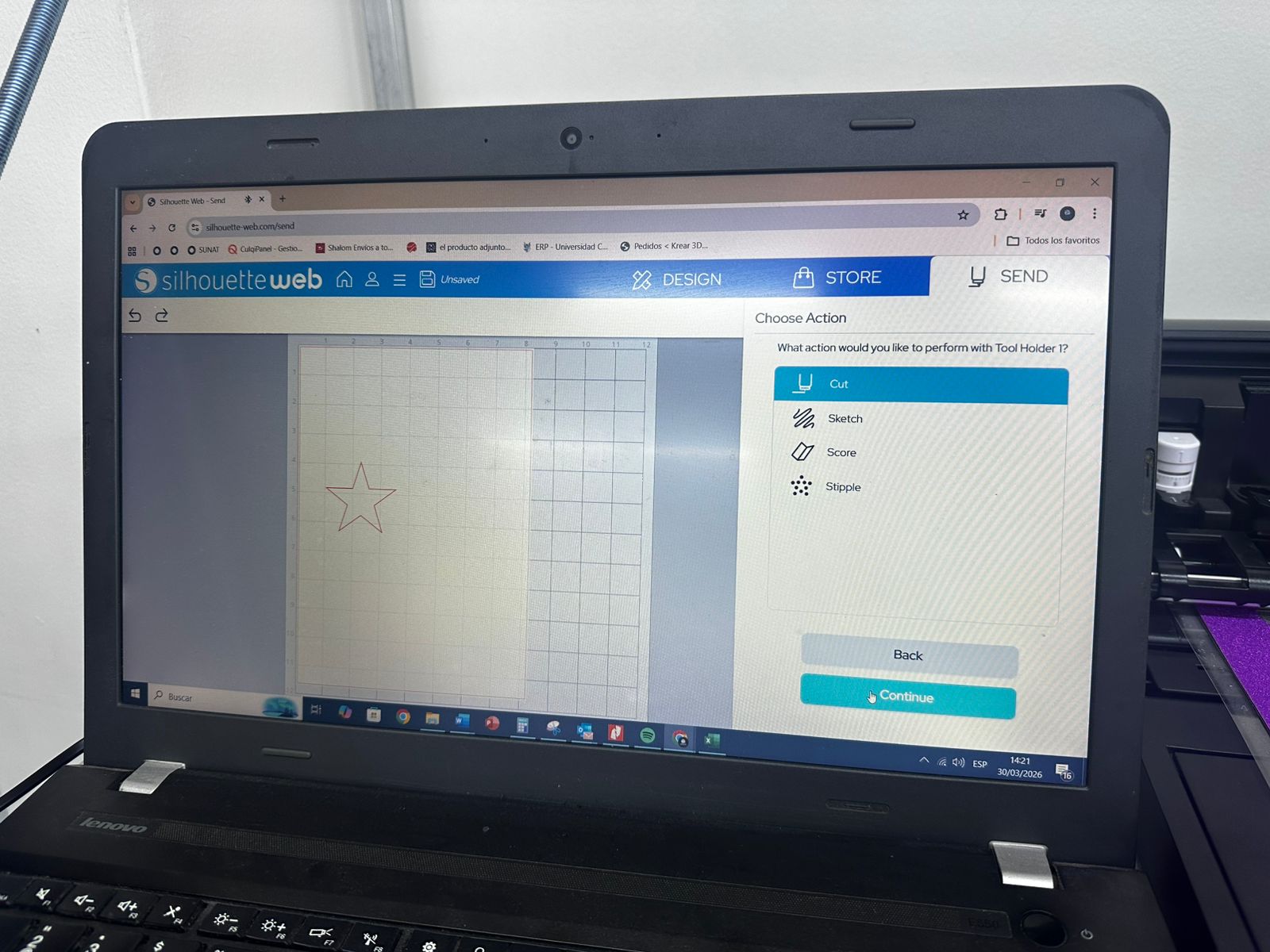
The design was prepared using Silhouette Studio, where different vector shapes such as a circle, a star, a heart, and text were created.
The software allows assigning different types of operations, such as:
- cut (for full cutting through the material),
- sketch (for drawing with a pen tool),
- score (for marking fold lines).
In addition to basic shapes, this workflow also allows importing images or logos, which can be printed on sticker paper and then cut following their contour, enabling more complex graphic applications.
Machine Setup
The material was placed on a cutting mat and aligned with the grid to ensure correct positioning. The mat was then loaded into the machine.
Cutting parameters such as blade depth, speed, and force were configured in the software depending on the material used. These parameters are critical to achieve a clean cut without damaging the backing layer.
Once configured, the file was sent to the machine, and the cutter followed the vector paths to produce the final shapes.

Post-Processing and Results
After cutting, the excess material was manually removed in a process known as "weeding", leaving only the desired shapes on the backing layer.
The results were successful, producing clean cuts for both shapes and text. Additionally, the possibility of printing a logo on sticker paper and then cutting it demonstrated how vinyl cutting can be combined with graphic workflows for more complex applications.
Key Learnings
This process highlighted the importance of selecting the correct parameters depending on the material, as well as the relationship between vector design and physical output. It also demonstrated how vinyl cutting can be extended beyond simple shapes to include graphic elements, making it a versatile tool for prototyping and visual communication.
Download Files
The design files used in this assignment can be downloaded below.