
Week 03 — Computer-Controlled Cutting
Group Assignment – Laser Cutter Characterization
1. Introduction
In this group activity, the basic safety and operation training for the lab’s laser cutter located in the Universidad del Pacifico in Lima. Afterwards, the main operating parameters of the machine were analyzed, including power, speed, laser focus, kerf, and assembly tolerances.
The objective of this practice was to understand how these parameters influence the cutting and engraving process, as well as to generate references for future digital fabrication work.
2. Safety Training
Before using the laser cutter, it is necessary to know the main parts of the machine and the safety conditions that guarantee correct use.
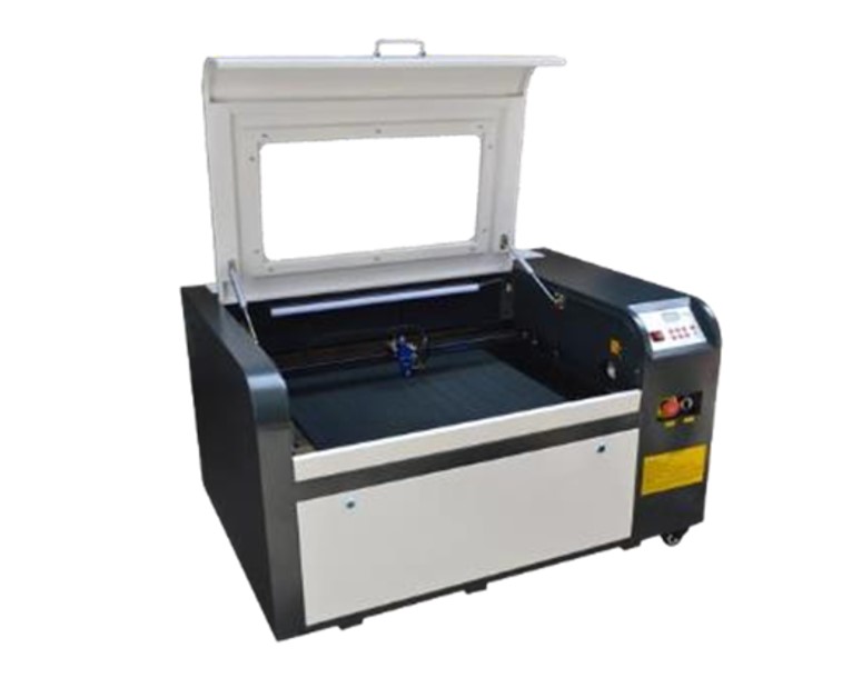
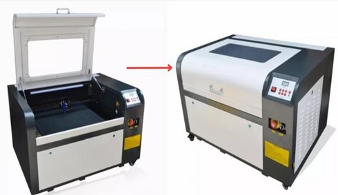
The laser cutter used in the lab is a Tauryc Laser CO₂, operated through the Meerk40t software. The system includes the main machine, a cooling chiller, and the gas extraction system.
According to the machine manual, the main components that must be identified are:
- Sealed cover
- Control panel
- Emergency button
- Laser power button
- Chiller or industrial cooler
These elements allow the equipment to be operated safely and the process to be stopped in case of emergency.
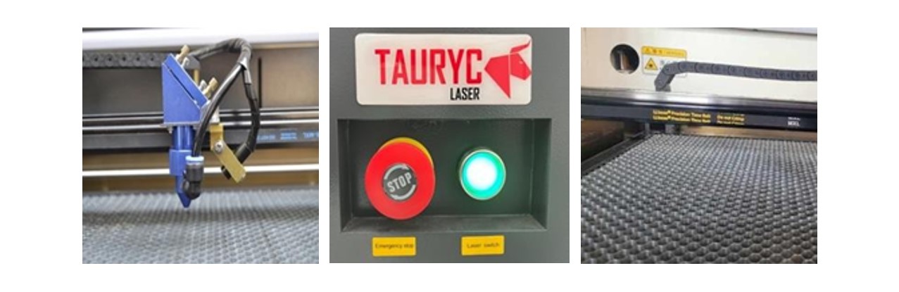
The interior of the laser cutter includes three main components:
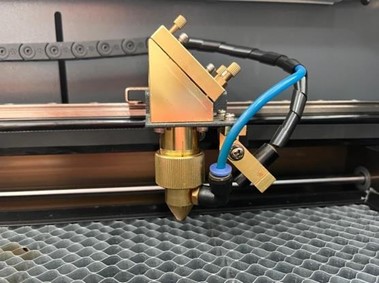
- Laser head: performs cutting, engraving, or carving operations.
- Ignition board: controls the activation of the CO₂ laser and the emergency button.
- Cutting bed: surface where the material to be processed is placed.
Precautions Before Operating
Before starting any work, it is necessary to verify the following conditions:
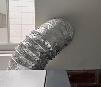
A. Exhaust system
The exhaust tube must be correctly connected and direct the gases outside the laboratory. This prevents the accumulation of smoke generated during cutting.
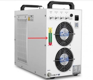
B. Chiller level
The chiller cools the laser tube using deionized water. It must be checked that the water level is within the indicated range to avoid overheating.
C. Closed cover
The machine cover must remain closed during the process to avoid exposure to laser radiation and gases.
D. Head condition
It is important to check that the head is clean and free of material residues. In addition, the internal mirrors of the optical system must not be manipulated.
3. Machine Preparation
Before making any cut, the following aspects must be properly prepared.
Platform leveling
The height of the cutting bed is adjusted using a leveling lever. To ensure the correct laser focus, a standard spacer is used to position the head approximately 1 cm away from the material.
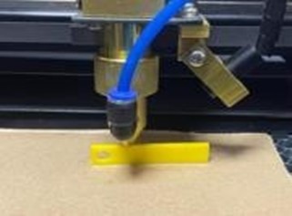
This adjustment is essential to obtain a precise cut.
Connection with the computer
Communication between the computer and the laser cutter is carried out using a USB-A to USB-B cable, similar to the one used by Arduino boards.
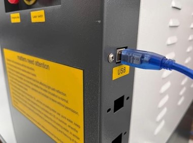
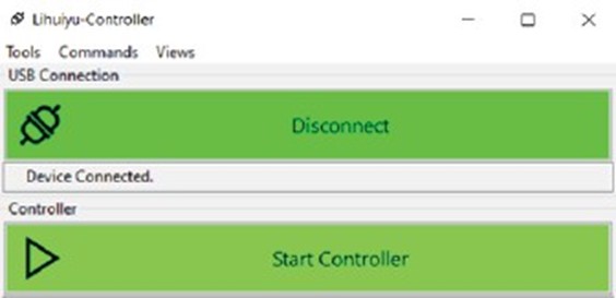
Inside the Meerk40t software, it must be verified that the connection is active in the Controller section.
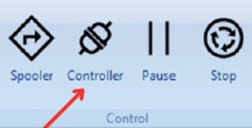
If the connection appears in yellow, it means that it is not active yet. When the status appears in green, the machine is ready to operate.
4. File Preparation
The Meerk40t software allows working in two ways:
- Import files
- Design directly in the program
Compatible files include:
- Raster images (PNG, JPG)
- Vector graphics (SVG)
Vector files are preferable for cutting because they allow modifying lines and geometries with greater precision.
5. Laser Operations
Different types of operations can be configured within the software:
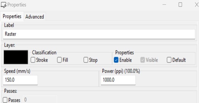
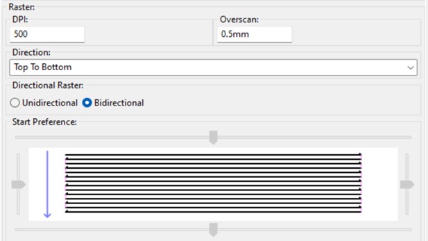
Raster
This is an operation intended to wear, outline, or mark an area of material according to the files that have been preloaded onto the cutting bed.
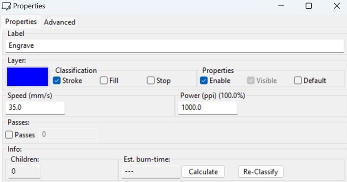
Engrave
This is an operation designed to perform superficial engravings on materials. Unlike “Raster,” which is responsible for wearing or scratching the material, engrave produces a softer finish.
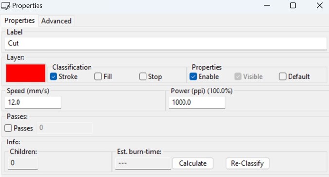
Cut
This is the ideal operation for cutting or outlining figures placed on the cutting bed. For this, two parameters are mainly used: speed and power.
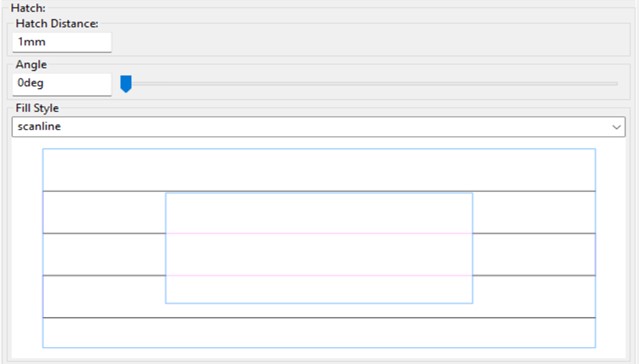
Hatch
This is an operation very similar to “Engrave,” but in this case, instead of engraving, it simply “shades” or fills the selected areas.
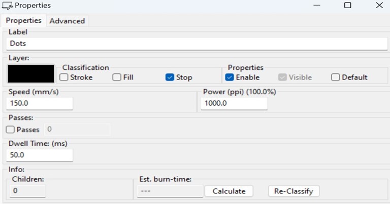
Dots
This is a simple operation that seeks to draw the images placed on the cutting bed using dots. The Dwell Time parameter indicates how long each specific point will be burned.
Each operation is mainly controlled through two parameters:
- Speed
- Laser power
These parameters determine the cutting depth and the quality of the finish.
6. Laser Characterization
To understand the behavior of the machine, tests were carried out by varying the main parameters of the system.
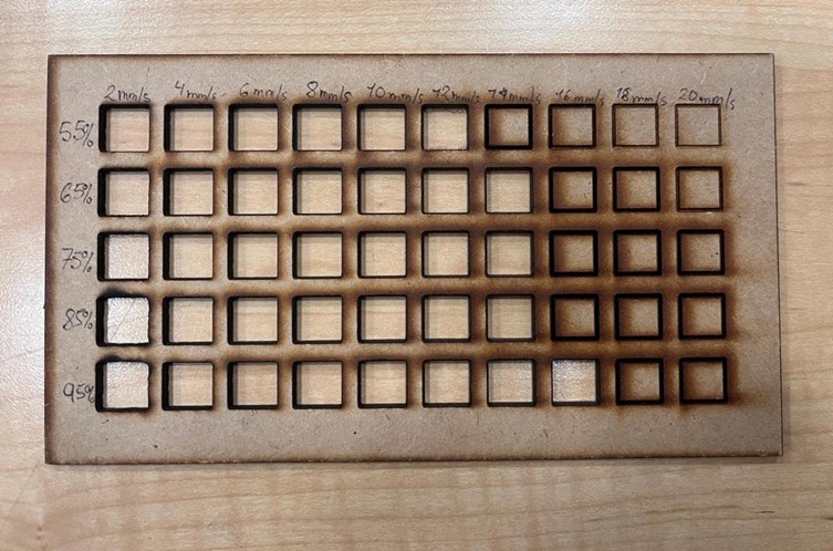
A 2 mm MDF sheet was used, which is a material sensitive to temperature and requires moderate power and PPI values to avoid excessive burning.
7. Tests Performed
Power vs Speed
Tests combining different power and speed values to determine which parameters produce a clean cut.
The process allowed us to understand how the laser cutter parameters influence the final cutting result. It was observed that small changes in speed or power can significantly affect the cut quality, especially in sensitive materials such as MDF.