
Assignment Requirements
Group assignment
- send a message between two projects
- probe communication between microcontrollers
Individual assignment
- design, build and connect wired or wireless nodes
- use network or bus addresses
- integrate local input and/or output devices
0) Group Assignment — Communication Between Devices
The group assignment for Week 11 was carried out at the Fab Lab Universidad del Pacífico, where the entire Fab Academy Lima team gathered to explore communication between microcontrollers.
During this session, we focused on understanding how devices can exchange data, either through wired or wireless communication. The objective was to observe how a message can be transmitted from one system to another, establishing the foundation of embedded networking.
Working together in the same physical space allowed us to test communication setups more effectively and understand the behavior of signals between different boards. This experience was essential to grasp the logic behind networking before applying it individually.
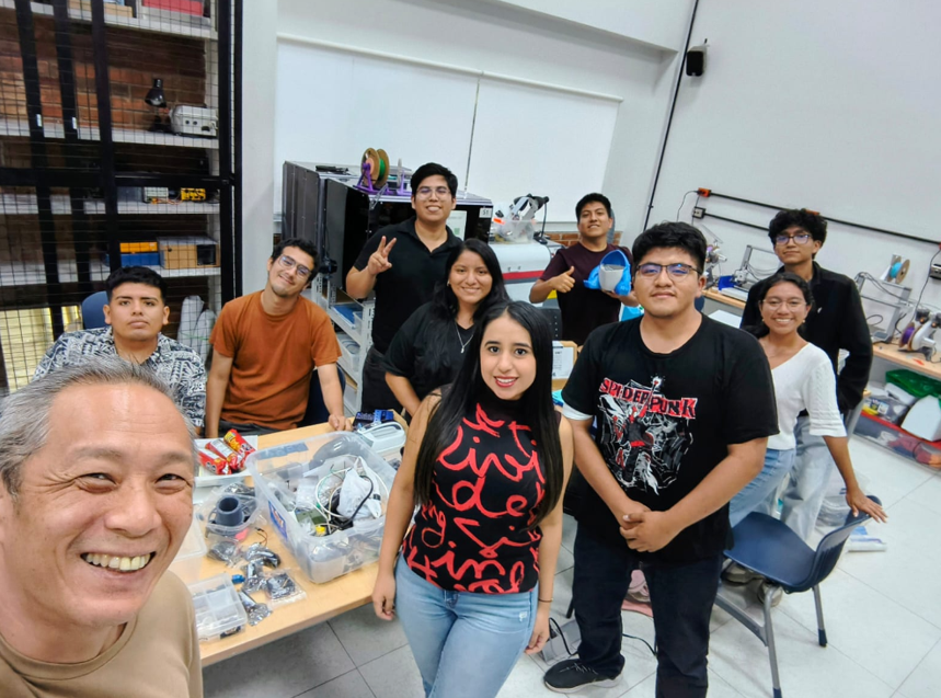
Group assignment session at Fab Lab Universidad del Pacífico.
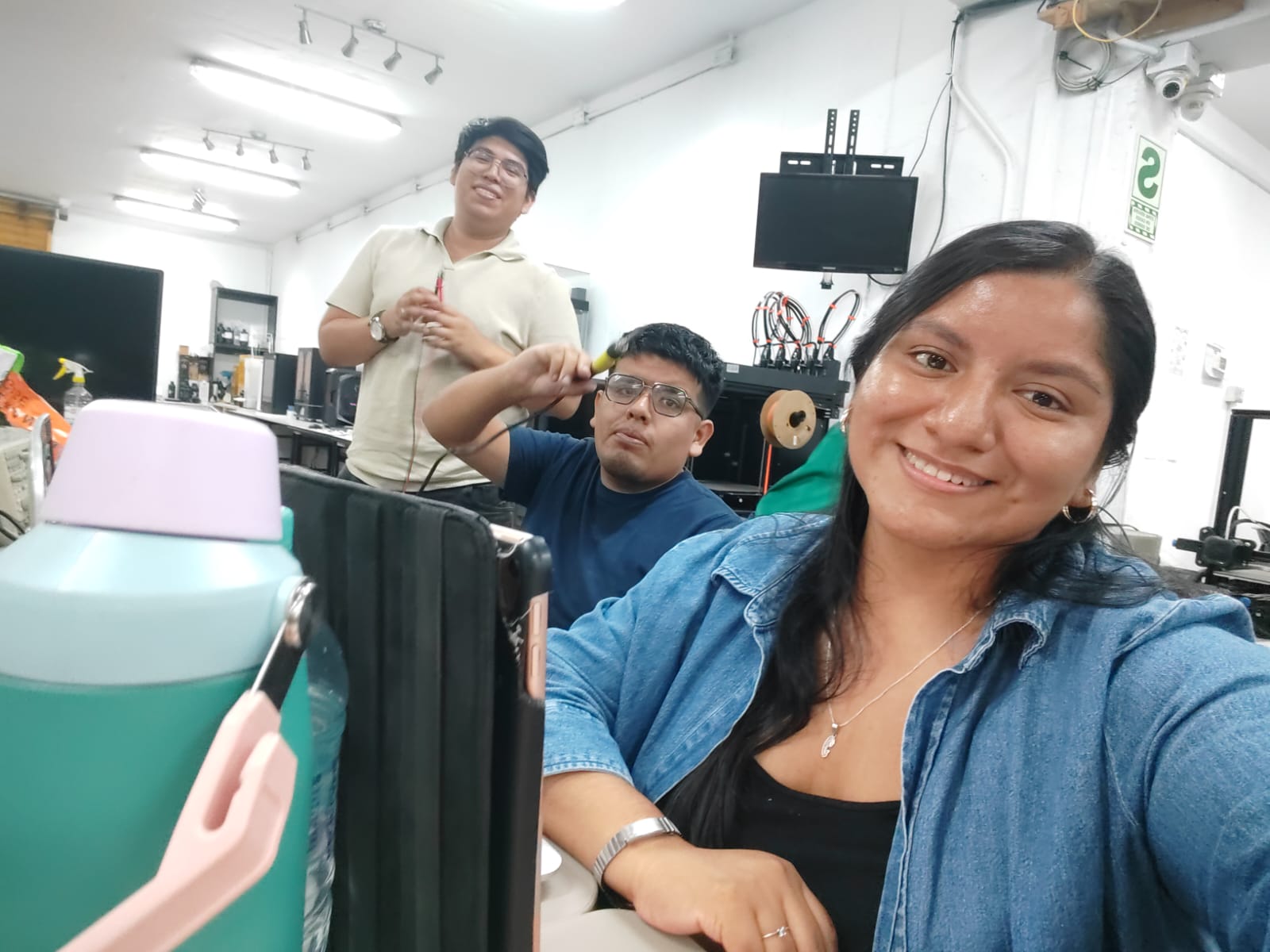
Collaborative continuation of the assignment at Fab Lab UNI.
After completing the group assignment, the individual work was developed collaboratively at Fab Lab UNI together with Carmencita and Jianfranco. Since we are still building our skills in electronics and networking, we decided to support each other and work as a team to better understand the implementation process.
This hybrid workflow reflects the Fab Lab Itinerante model, combining collective learning during group sessions with collaborative development during individual assignments.
1) Initial Approach and Learning Strategy
At the beginning of this week, we were not entirely familiar with how to implement communication between microcontrollers. For this reason, we decided to start by reviewing documentation from previous Fab Academy students.
One of the key references was the work of Jhonatan Cortés, who developed a system where an ESP32 acts as a web server. In his project, a tablet connects to the microcontroller through WiFi, allowing the user to control an RGB LED through a web interface.
This example helped us understand the logic behind embedded networking, including concepts such as IP addresses, web servers, and wireless communication between devices.
However, we also realized that implementing a full web server required a deeper understanding of networking than we currently have, which led us to explore alternative approaches.
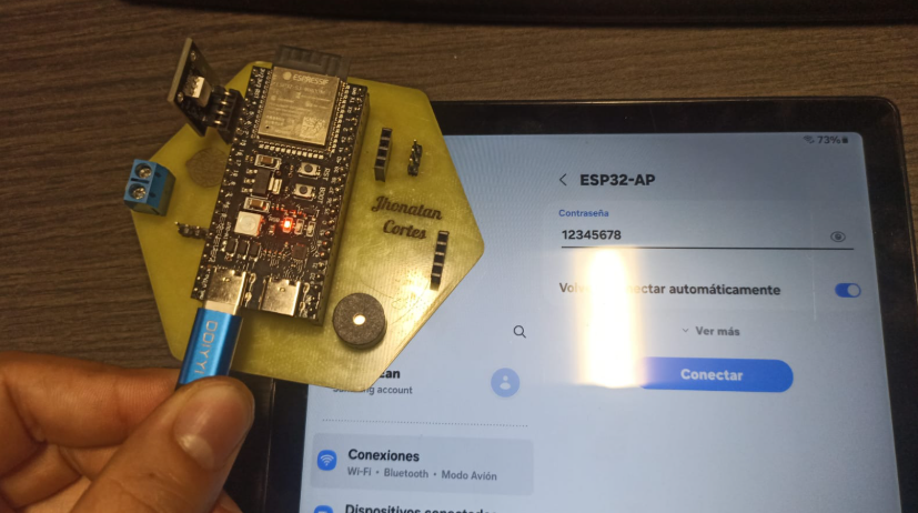
Reference project based on ESP32 web server communication.
2) Choosing the Communication Strategy
After analyzing different approaches for implementing communication between devices, we realized that creating a web server directly on the ESP32 would require a deeper understanding of networking concepts, including HTTP requests, server handling, and IP-based communication.
Since we are still developing our knowledge in embedded electronics, we decided to adopt a more accessible and efficient solution that would allow us to focus on understanding the interaction between input, output, and communication systems.
For this reason, we chose to work with RemoteXY, a platform that simplifies the process of creating wireless interfaces by allowing users to design control panels through a drag-and-drop environment.
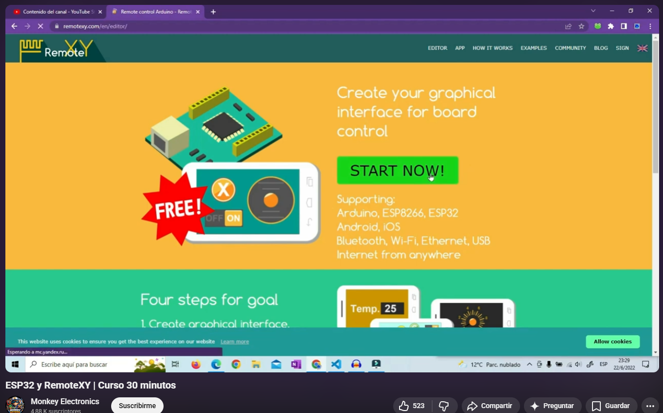
Exploring alternative approaches for embedded communication.
3) RemoteXY — Interface Design
RemoteXY is a platform that allows the creation of mobile or web-based interfaces to control microcontrollers wirelessly. Instead of manually programming a server, it provides a visual environment where elements can be added easily.
Using this tool, we designed an interface that includes:
- ON/OFF toggle button
- RGB control for LED output
- Visual display elements for feedback
This interface acts as the main communication bridge between the user and the microcontroller, allowing real-time interaction through a mobile device.
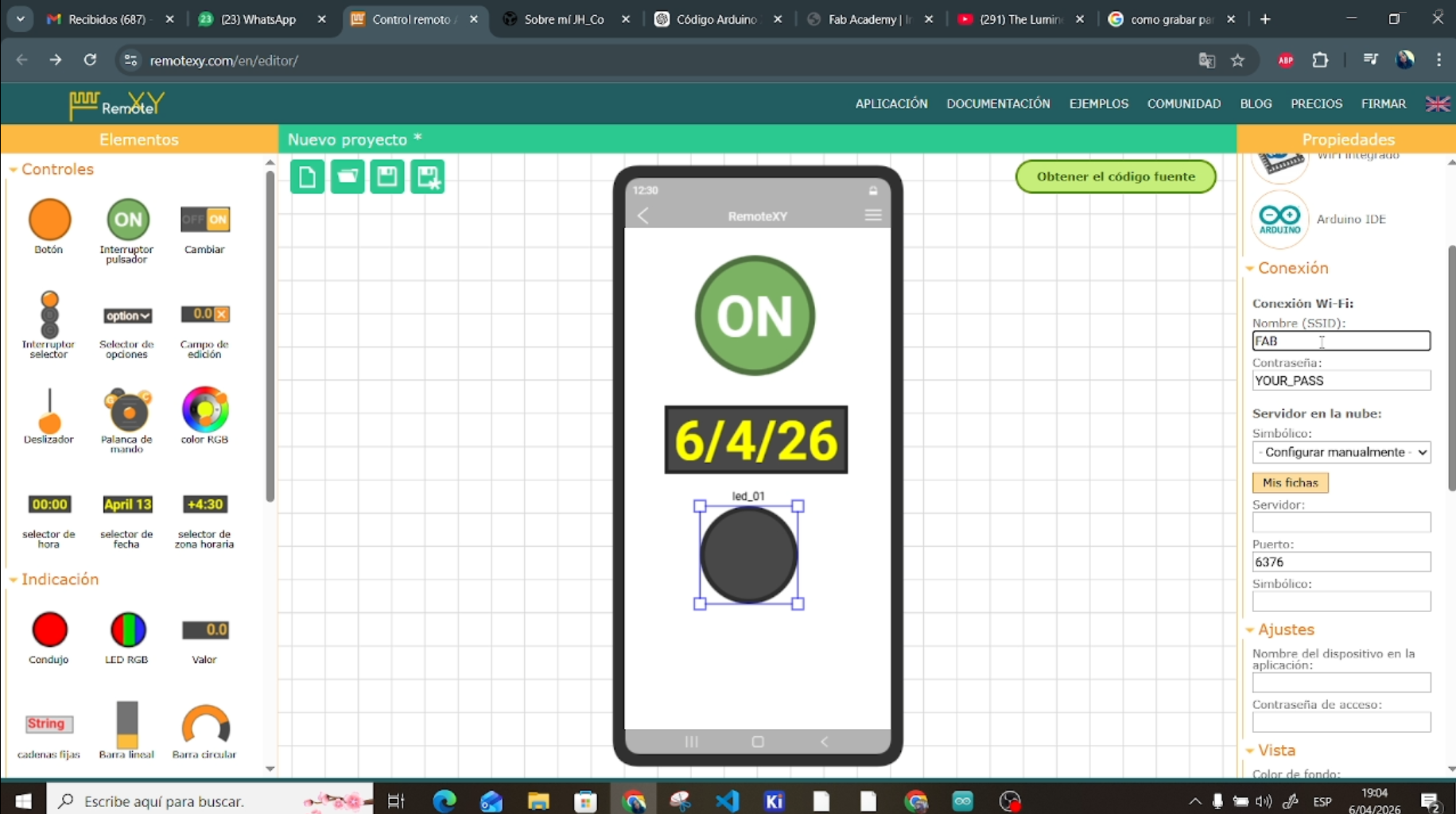
Interface created using RemoteXY drag-and-drop editor.
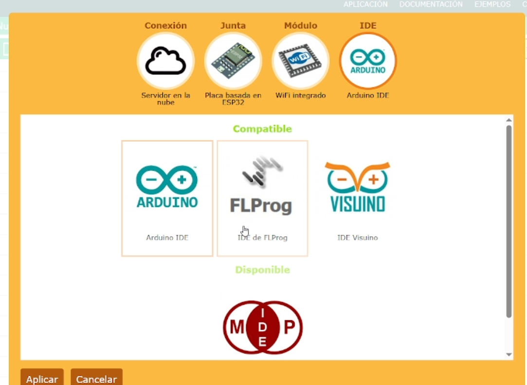
4) Network Configuration
After designing the interface, the next step was configuring the communication parameters. RemoteXY allows defining how the microcontroller connects to the network and how the interface will communicate with it.
In this case, we configured the system as follows:
- Connection type: Cloud server
- Microcontroller: ESP32 (Xiao ESP32-C3)
- Communication method: Built-in WiFi
- Development environment: Arduino IDE
We also defined the WiFi credentials, including the network name (SSID) and password, as well as additional parameters such as server configuration and communication port.
These parameters allow the microcontroller to connect to the network and establish a communication channel with the RemoteXY interface.
WiFi configuration setup.
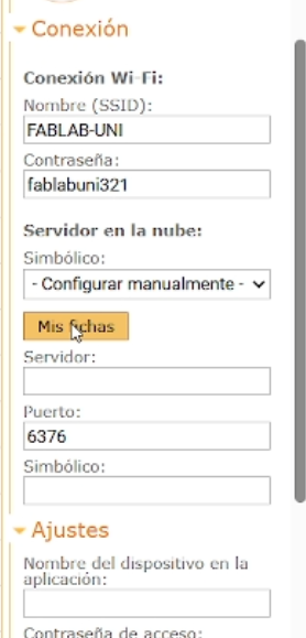
Server and connection parameters.
5) Account Setup and Access Token
To enable communication through RemoteXY cloud services, it was necessary to create an account on the platform. This account allows managing projects and generating secure connections between devices.
One of the most important elements in this process is the access token. This token acts as a unique identifier that links the interface with the microcontroller.
The token is automatically generated by the platform and must be included in the Arduino code. Without this token, the communication between the device and the interface would not be possible.
This step is critical because it ensures that the system can connect securely and function correctly in a wireless environment.
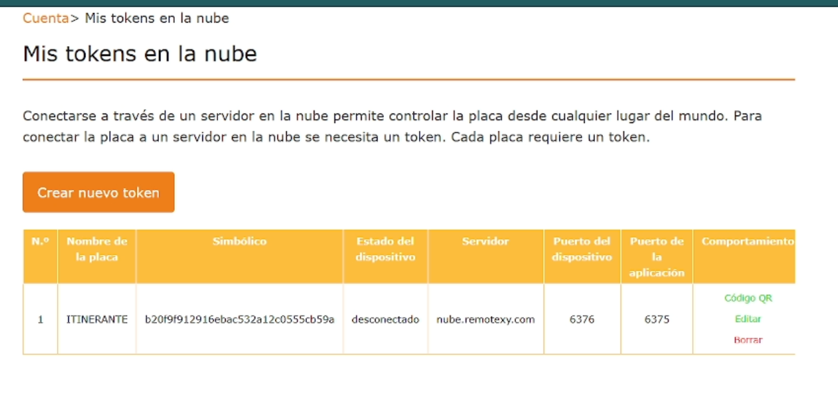
Generated token and connection authentication process.
6) Code Generation and Arduino Integration
Once the interface and network configuration were completed in RemoteXY, the platform automatically generated the full source code required to run the system on the microcontroller.
This code includes all the necessary libraries, communication protocols, and variables needed to link the interface elements (buttons, sliders, RGB controls) with the physical outputs connected to the board.
We then moved to the Arduino IDE, where we connected our Xiao ESP32-C3 to the computer and prepared the development environment.
The generated code was copied directly into the Arduino IDE, ensuring that all required libraries were properly installed so the program could compile and upload successfully.
//////////////////////////////////////////////
//        RemoteXY include library          //
//////////////////////////////////////////////

#define REMOTEXY_MODE__WIFI_CLOUD

#include
#include
#include
#include
#include
#include

// RemoteXY connection settings
#define REMOTEXY_WIFI_SSID "FABLAB-UNI"
#define REMOTEXY_WIFI_PASSWORD "fablabuni321"
#define REMOTEXY_CLOUD_SERVER "cloud.remotexy.com"
#define REMOTEXY_CLOUD_PORT 6376
#define REMOTEXY_CLOUD_TOKEN "cda5e7167a8af520f36a66c4415034a6"
#define REMOTEXY_ACCESS_PASSWORD "1234"

#pragma pack(push, 1)
uint8_t const PROGMEM RemoteXY_CONF_PROGMEM[] = {
  255,3,0,3,0,71,0,19,0,0,0,88,73,65,79,69,83,80,51,50,
  74,73,65,78,0,31,1,106,200,1,1,4,0,10,27,11,46,46,48,4,
  26,31,79,78,0,31,79,70,70,0,65,33,68,39,39,112,13,8,119,93,
  20,77,6,94,26,129,13,151,83,34,64,17,76,97,98,101,108,0 };

struct {
  uint8_t pushSwitch_01;
  uint8_t editTime_01_hour;
  uint8_t editTime_01_minute;

  uint8_t led_01_r;
  uint8_t led_01_g;
  uint8_t led_01_b;

  uint8_t connect_flag;
} RemoteXY;
#pragma pack(pop)

/////////////////////////////////////////////
//           OLED CONFIG                  //
/////////////////////////////////////////////

#define SCREEN_WIDTH 128
#define SCREEN_HEIGHT 64
#define OLED_ADDR 0x3C

#define SDA_PIN D4
#define SCL_PIN D5

Adafruit_SSD1306 display(SCREEN_WIDTH, SCREEN_HEIGHT, &Wire, -1);

/////////////////////////////////////////////
//           PINES                        //
/////////////////////////////////////////////

#define PIN_R D3
#define PIN_G D2
#define PIN_B D1
#define PIN_SERVO D7

Servo miServo;

/////////////////////////////////////////////
//                SETUP                   //
/////////////////////////////////////////////

void setup()
{
  RemoteXY_Init ();

  // RGB
  pinMode(PIN_R, OUTPUT);
  pinMode(PIN_G, OUTPUT);
  pinMode(PIN_B, OUTPUT);

  // Servo
  miServo.attach(PIN_SERVO);

  // OLED
  Wire.begin(SDA_PIN, SCL_PIN);
  display.begin(SSD1306_SWITCHCAPVCC, OLED_ADDR);
  display.clearDisplay();

  display.setTextSize(1);
  display.setTextColor(WHITE);
  display.setCursor(0, 0);
  display.println("Sistema iniciado");
  display.display();
}

/////////////////////////////////////////////
//                LOOP                    //
/////////////////////////////////////////////

void loop()
{
  RemoteXY_Handler ();

  // ====== NUEVA LOGICA RGB ======
  static uint8_t lastState = 0;
  static int colorIndex = 0;

  // Detectar cambio OFF -> ON
  if (RemoteXY.pushSwitch_01 == 1 && lastState == 0) {
    colorIndex++;
    if (colorIndex > 5) colorIndex = 0;
  }

  lastState = RemoteXY.pushSwitch_01;

  // CONTROL RGB con colores predefinidos
  if (RemoteXY.pushSwitch_01 == 1) {

    switch (colorIndex) {
      case 0: // Rojo
        analogWrite(PIN_R, 255);
        analogWrite(PIN_G, 0);
        analogWrite(PIN_B, 0);
        break;

      case 1: // Verde
        analogWrite(PIN_R, 0);
        analogWrite(PIN_G, 255);
        analogWrite(PIN_B, 0);
        break;

      case 2: // Azul
        analogWrite(PIN_R, 0);
        analogWrite(PIN_G, 0);
        analogWrite(PIN_B, 255);
        break;

      case 3: // Amarillo
        analogWrite(PIN_R, 255);
        analogWrite(PIN_G, 255);
        analogWrite(PIN_B, 0);
        break;

      case 4: // Morado
        analogWrite(PIN_R, 255);
        analogWrite(PIN_G, 0);
        analogWrite(PIN_B, 255);
        break;

      case 5: // Cyan
        analogWrite(PIN_R, 0);
        analogWrite(PIN_G, 255);
        analogWrite(PIN_B, 255);
        break;
    }

  } else {
    // Apagar RGB
    analogWrite(PIN_R, 0);
    analogWrite(PIN_G, 0);
    analogWrite(PIN_B, 0);
  }

  // 🎮 CONTROL SERVO (SE MANTIENE IGUAL)
  if (RemoteXY.pushSwitch_01 == 1) {
    miServo.write(90);
  } else {
    miServo.write(0);
  }

  // 🖥️ OLED (SE MANTIENE IGUAL)
  display.clearDisplay();

  display.setCursor(0,0);
  display.println("WEEK11 JIAN");

  display.setCursor(0,15);
  display.print("BUTTON: ");
  display.println(RemoteXY.pushSwitch_01 ? "ON" : "OFF");

  display.setCursor(0,30);
  display.print("RGB:");
  display.print(colorIndex); // ahora mostramos el color activo
  display.println("");

  display.setCursor(0,45);
  display.print("Hora: ");
  display.print(RemoteXY.editTime_01_hour);
  display.print(":");
  display.println(RemoteXY.editTime_01_minute);

  display.display();

  RemoteXY_delay(100);
}
7) QR Connection and Mobile Interface
One of the most important features of RemoteXY is the automatic generation of a QR code, which allows quick access to the control interface.
By scanning this QR code using a mobile device or tablet, we were able to instantly open the interface without needing to manually configure IP addresses or network settings.
This simplified the connection process significantly, allowing us to focus on testing the interaction between the interface and the microcontroller.
The mobile device then acted as a remote controller, sending commands wirelessly to the ESP32.
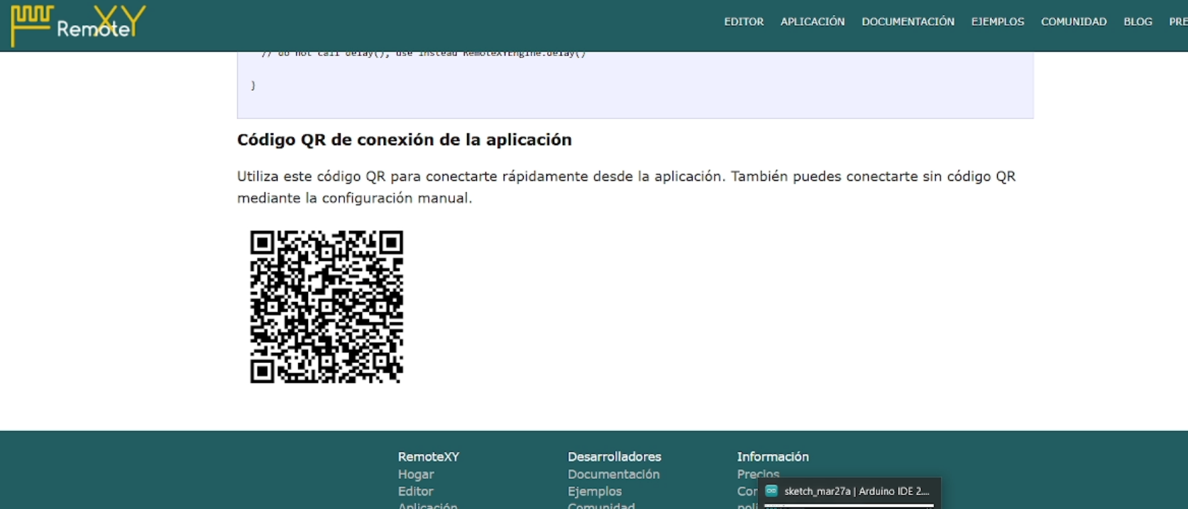
QR code used to connect the mobile interface to the system.
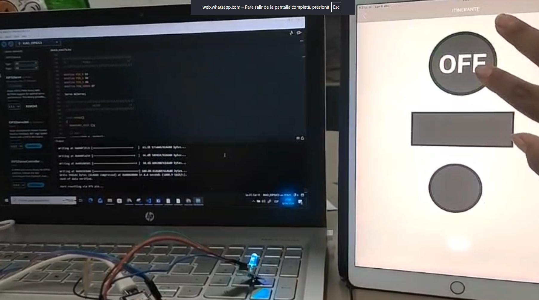
8) Wireless Testing and System Behavior
After uploading the code to the microcontroller and connecting through the QR interface, we began testing the system in real time.
Using a tablet placed next to the setup, we interacted with the interface elements and observed how the microcontroller responded to each command.
The system successfully demonstrated wireless communication, allowing us to:
- Turn the LED ON and OFF remotely
- Change the RGB color values
- Display information on the OLED screen
- Show custom messages such as "Itinerante"
- Display time and system feedback
This confirmed that the ESP32 was correctly receiving data from the network and translating it into physical outputs, completing the communication loop between interface and hardware.
9) System Integration — Input, Output and Networking
At this stage, the project evolved into a complete embedded system where communication, input, and output were fully integrated. The Xiao ESP32-C3 microcontroller acted as the central node, receiving data from the RemoteXY interface and controlling physical devices in real time.
The system can be understood as a communication loop:
- User interaction from mobile device (input)
- Wireless transmission via WiFi
- Data processing inside the microcontroller
- Physical response through output devices
This workflow demonstrates how embedded networking allows digital interfaces to interact directly with physical systems.
10) Output Devices — LED and OLED Display
The system included two main output devices: an RGB LED and an OLED display, both connected to the ESP32-based board.
The RGB LED responded to commands sent from the RemoteXY interface, allowing real-time control of color and state (ON/OFF). This demonstrated how digital signals received through a network can directly control physical components.
In parallel, the OLED display provided visual feedback, showing system status, custom text such as "Itinerante", and dynamic information like time.
This combination of outputs created a more complete system, where both visual feedback and physical response were integrated into the same workflow.
RGB LED responding to wireless commands.
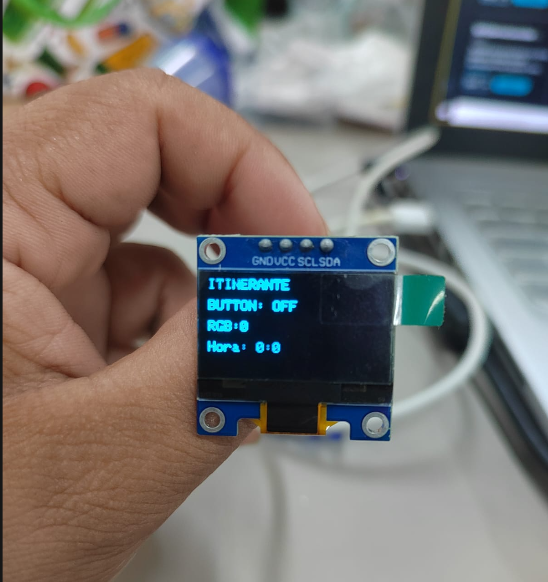
OLED display showing system feedback.
11) System Logic and Behavior
The logic of the system is based on the interaction between remote input and physical output. When a user interacts with the interface (for example, pressing a button or changing a color value), the command is transmitted through the network and interpreted by the microcontroller.
The ESP32 processes this information and executes the corresponding action, such as:
- Activating or deactivating the LED
- Changing RGB values
- Updating text and information on the OLED display
This demonstrates how a microcontroller can act as a bridge between digital interfaces and physical systems, enabling real-time interaction.
Through this implementation, we were able to understand how networking expands the capabilities of embedded systems, allowing them to operate beyond local inputs and become remotely controlled devices.

System behavior responding to remote inputs in real time.
12) Reflection — Networking as a System Layer
This week allowed me to understand how communication can transform a microcontroller into a connected system rather than an isolated device. By integrating wireless networking, the project evolved from a local interaction model into a system that can be controlled remotely.
Working collaboratively with Carmencita and Jianfranco was fundamental during this process. Since we are still learning the foundations of electronics and networking, developing the assignment together allowed us to better understand each step and support each other when facing technical challenges.
One of the most important lessons was understanding that networking is not only about sending data, but about creating a communication layer that connects interfaces, devices, and users in real time.
Through RemoteXY, we were able to simplify this process and focus on understanding the logic behind wireless communication, rather than getting blocked by complex server configurations.
Collaborative development session at Fab Lab UNI.
13) Connection to Final Project
This week has a direct impact on the development of my final project. Previously, I had already explored input devices (LDR sensors) and output devices (servomotors and OLED displays), but now I understand how to connect these elements through a communication system.
In my project, I am developing an adaptive system where light conditions are measured using sensors, and based on this data, a set of servomotors will control the movement of a geometric panel.
With the knowledge from this week, I can now envision this system as a networked device, where monitoring and control could be performed remotely. This opens the possibility of managing multiple modules distributed in different locations, especially considering that the project is intended for remote environments such as the Amazon.
Additionally, the idea of integrating wireless communication aligns with the concept of an adaptive and responsive system, where data can be transmitted, monitored, and adjusted in real time.
Even though the current prototype is still under development, this week provided a clear understanding of how communication can be integrated into my project, reinforcing the idea of a connected and intelligent architectural system.
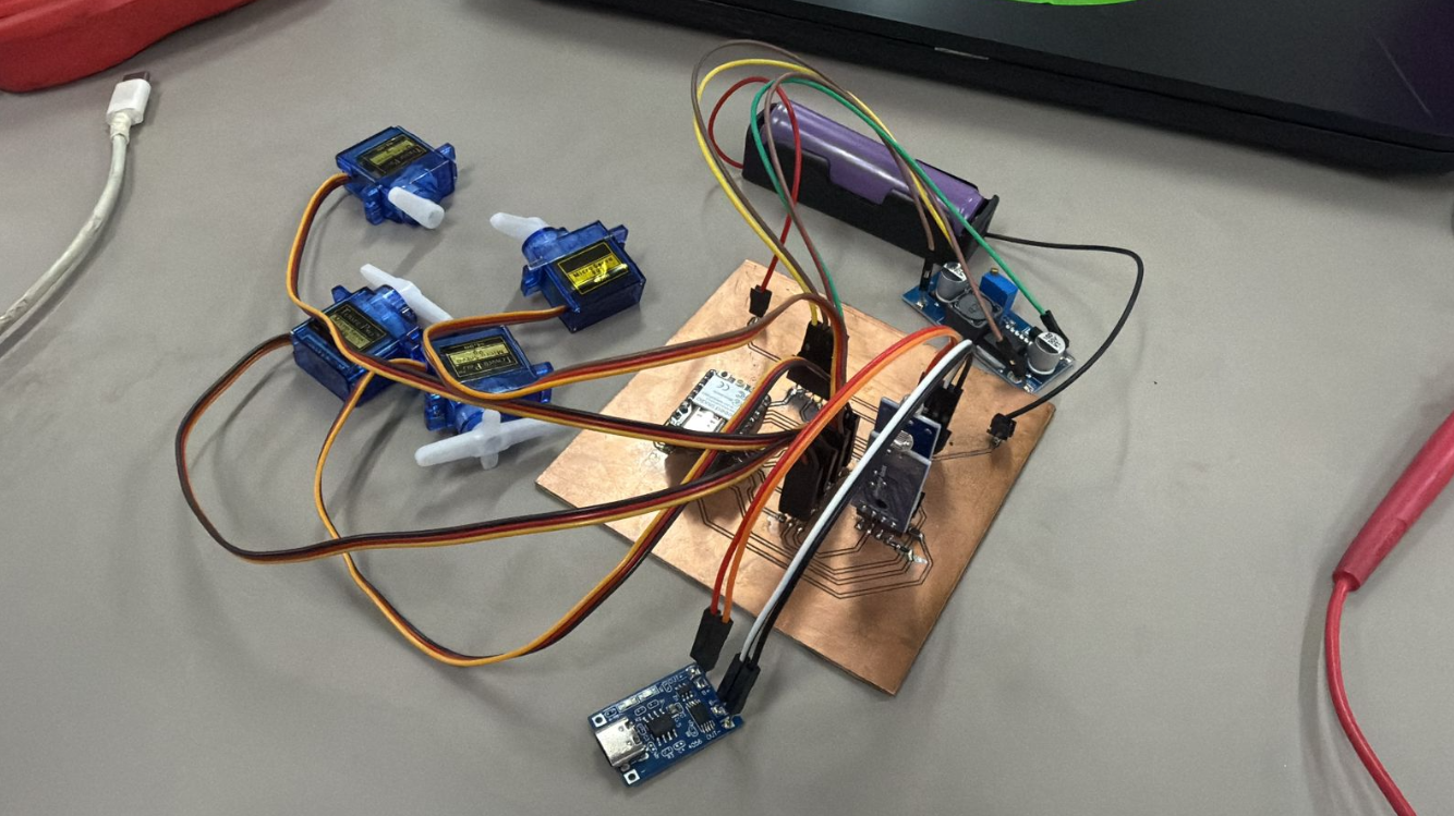
Progress of final project integrating sensors, actuators, and communication systems.
14) Files
The following files correspond to the development of the embedded networking system for Week 11, including configuration, code, and documentation resources.
- Arduino Code (RemoteXY Integration) Download .INO File
- RemoteXY Configuration File Download Configuration
- Interface Design Reference Download Image
These files document the implementation of a wireless communication system between a mobile interface and a microcontroller, demonstrating real-time interaction with embedded devices.