
Assignment Requirements
Group assignment
- measure the power consumption of an output device
Individual assignment
- add an output device to a microcontroller board you've designed and program it
Progress Status
Output testing and analysis
OLED output + joystick interaction
Interactive system explanation
1) Individual Assignment — From Input to Output
For this week's assignment, instead of designing a completely new system, I decided to continue developing the electronic board created during Week 09. That system already included both input devices (sensors) and an output device (OLED display), making it a perfect foundation to explore output control in more depth.
The OLED display, which was previously used to visualize sensor data, became the main output device for this assignment. However, the approach changed significantly: instead of displaying passive data, the system was transformed into an interactive interface.
To achieve this, a joystick module was introduced as a new input device. This allowed real-time interaction with the system, enabling control of visual elements on the OLED screen.
The final result was an interactive implementation of the classic Snake game, where the joystick controls movement and the OLED display renders the game in real time.
OLED display used as output device (Week 09).
Final PCB used as base for Week 10.
0) Group Assignment — Output Analysis
As part of the group assignment for Week 10, we focused on understanding how output devices behave when controlled by a microcontroller. The main objective was to analyze how electrical signals translate into visible or physical outputs, and how power consumption varies depending on the device.
This included observing how devices such as displays and actuators respond to digital signals, as well as identifying the electrical requirements needed for stable operation.
The complete group documentation can be accessed at the following link:
Fab Academy Lima — Week 10 Group Assignment
During this week, we also coordinated both virtual and in-person sessions, continuing the Fab Itinerante model, where part of the team worked from Fab Lab UNI while others participated remotely.
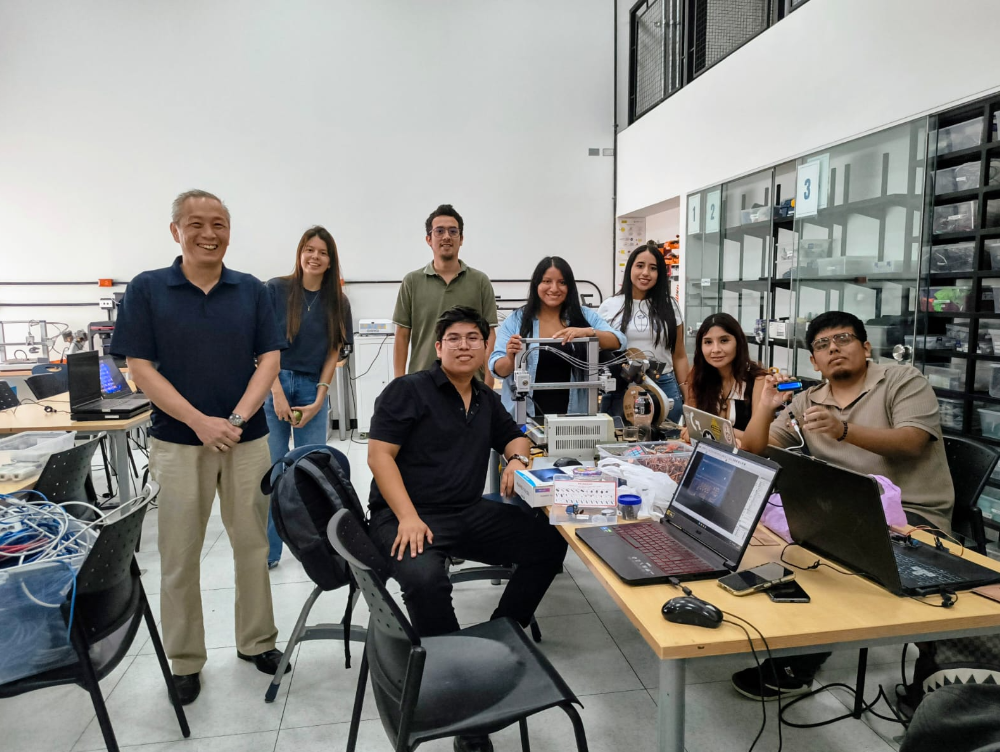
Group coordination session at Fab Lab UP.
2) Output Device — OLED Display
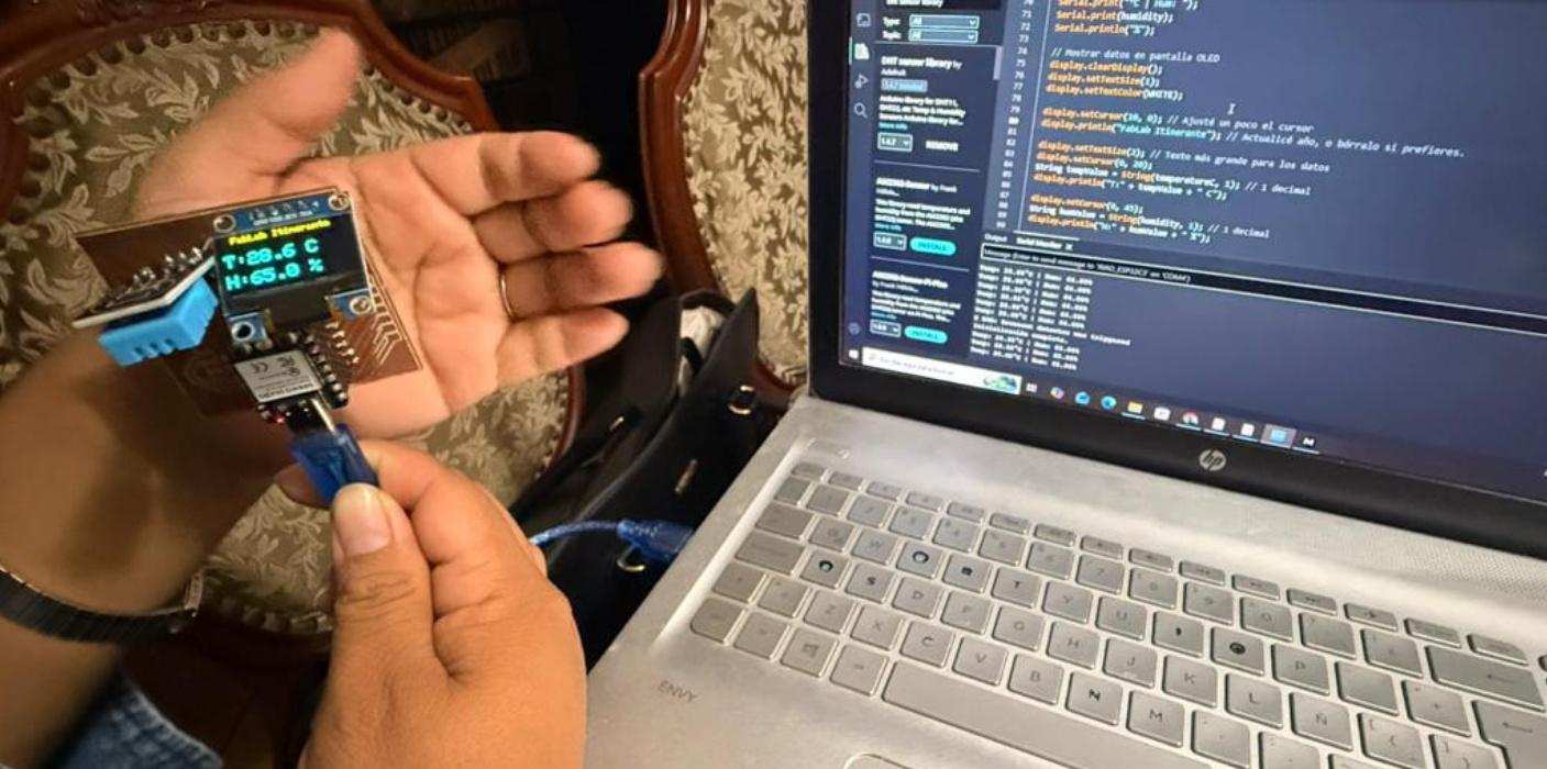
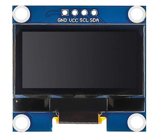
For this week's assignment, the main output device used was an OLED display, which had already been integrated into the PCB developed during Week 09. This display operates by receiving digital signals from the microcontroller and translating them into visual information.
Unlike traditional displays, OLED screens do not require a backlight. Instead, each pixel emits its own light, allowing for higher contrast and lower power consumption. This makes them ideal for embedded systems and compact electronic projects.
The display used in this project communicates with the microcontroller through the I2C protocol, which requires only two data lines: SDA (data) and SCL (clock). This simplifies wiring and reduces the number of pins needed.
In Week 09, this display was used to show sensor readings such as temperature, humidity, and light levels. However, for Week 10, its role evolved into a dynamic output device capable of rendering interactive graphics.
OLED display integrated in the PCB.
Display used to visualize sensor data (Week 09).
3) From Passive Output to Interactive System
In the previous week, the OLED display functioned as a passive output device, meaning it only displayed data coming from sensors without any user interaction. The system was limited to reading environmental inputs and presenting them visually.
For Week 10, the goal was to transform this passive system into an interactive one. Instead of simply displaying data, the OLED screen would now respond dynamically to user input, creating a real-time feedback loop between input and output.
This shift represents a key concept in embedded systems: the transition from monitoring (input-only) to interaction (input + output). By combining both elements, it becomes possible to create responsive interfaces and interactive applications.
To achieve this, a joystick was introduced as a new input device, enabling control over what is displayed on the screen. This combination allowed the system to evolve into a simple interactive game.
Previous sensor testing (input stage).
Transition to interactive output behavior.
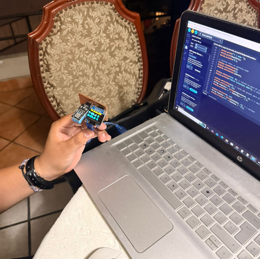
4) System Implementation — OLED + Joystick
For Week 10, the system developed in Week 09 was reused and extended to incorporate a more interactive behavior. Since both Carmencita and I are still learning the fundamentals of electronics, we decided to work collaboratively during this stage, supporting each other in understanding the integration between input and output devices.
The system is based on the Xiao ESP32-C3 microcontroller, where an OLED display was used as the main output device and a joystick module was added as a new input device. The joystick was connected to analog pins A0 and A1 to read the X and Y axes, while the button was configured using INPUT_PULLUP.
The analog values obtained from the joystick are processed using the analogRead() function, allowing the system to detect movement directions. At the same time, the OLED display communicates with the microcontroller through the I2C protocol (SDA and SCL), enabling efficient real-time updates.
Through this integration, the system evolved from simply displaying sensor data to generating dynamic visual outputs based on user interaction.
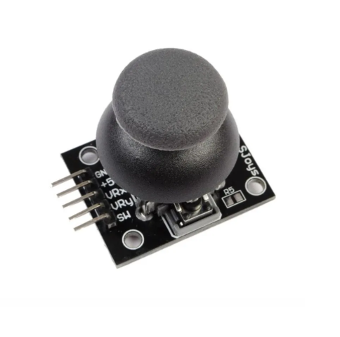
Joystick integration as input device.
OLED display used as output device.
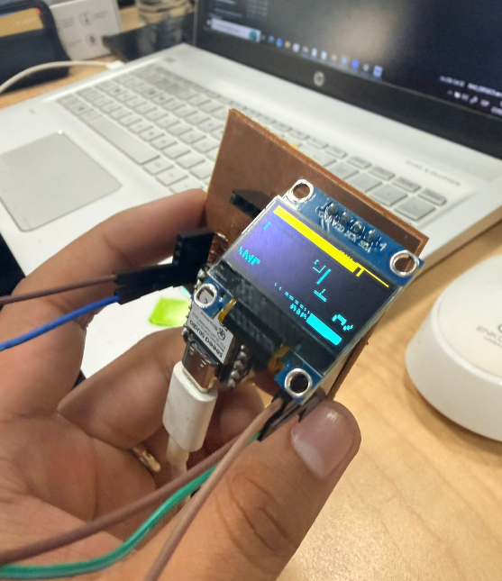
5) Interactive Output — Snake Game
To test the system in a more dynamic way, we implemented a simple version of the classic Snake game. In this case, the joystick controls the movement of the snake, while the OLED display renders the game in real time.
The joystick input is translated into directional commands (up, down, left, right), which are processed by the microcontroller to update the position of the snake. The OLED screen continuously refreshes to display the movement, food generation, and game state.
This implementation demonstrates how an embedded system can combine both input and output devices to create an interactive interface, moving beyond static visualization into real-time user interaction.
Additionally, this exercise reinforced our understanding of how analog signals can control digital behavior and how graphical interfaces can be generated on low-resource devices.
Snake game running on OLED display.
6) Arduino Code — OLED + Joystick (Snake Game)
The following code was used to control both the joystick input and the OLED display output. This program reads analog values from the joystick, processes directional movement, and updates the Snake game in real time on the screen.
The implementation combines input and output systems into a single interactive application, demonstrating how a microcontroller can process real-time data and generate dynamic visual feedback.
// ========================= LIBRARIES =========================
#include <Wire.h>
#include <Adafruit_GFX.h>
#include <Adafruit_SSD1306.h>

// ========================= DISPLAY CONFIG =========================
#define ANCHO_PANTALLA 128
#define ALTO_PANTALLA 64
#define OLED_RESET -1

Adafruit_SSD1306 display(ANCHO_PANTALLA, ALTO_PANTALLA, &Wire, OLED_RESET);

// ========================= INPUT PINS =========================
const int pinEjeX = A0;
const int pinEjeY = A1;
const int pinBoton = A2;

// ========================= GAME CONFIG =========================
#define TAMAÑO_BLOQUE 4
#define MAX_SERPIENTE 200
#define FPS_JUEGO 10

enum Direccion { QUIETO, ARRIBA, ABAJO, IZQUIERDA, DERECHA };

struct Punto {
  int x;
  int y;
};

// ========================= VARIABLES =========================
Punto serpiente[MAX_SERPIENTE];
int largoSerpiente = 2;
Punto comida;

Direccion dirActual = DERECHA;
Direccion dirNueva = DERECHA;

bool juegoTerminado = false;
unsigned long score = 0;
unsigned long ultimoFrame = 0;

const int umbralBajo = 1000;
const int umbralAlto = 3000;

// ========================= SETUP =========================
void setup() {
  Serial.begin(115200);
  pinMode(pinBoton, INPUT_PULLUP);

  if(!display.begin(SSD1306_SWITCHCAPVCC, 0x3C)) {
    Serial.println("Error OLED");
    for(;;);
  }

  resetJuego();
}

// ========================= LOOP =========================
void loop() {
  manejarInput();

  if (juegoTerminado) {
    mostrarGameOver();
    if (digitalRead(pinBoton) == LOW) {
      delay(300);
      resetJuego();
    }
    return;
  }

  if (millis() - ultimoFrame < (1000 / FPS_JUEGO)) return;
  ultimoFrame = millis();

  actualizarJuego();

  display.clearDisplay();
  dibujarMuro();
  dibujarSerpiente();
  dibujarComida();
  display.display();
}

// ========================= INPUT =========================
void manejarInput() {
  int valX = analogRead(pinEjeX);
  int valY = analogRead(pinEjeY);

  if (valX < umbralBajo && dirActual != DERECHA) dirNueva = IZQUIERDA;
  else if (valX > umbralAlto && dirActual != IZQUIERDA) dirNueva = DERECHA;
  else if (valY < umbralBajo && dirActual != ABAJO) dirNueva = ARRIBA;
  else if (valY > umbralAlto && dirActual != ARRIBA) dirNueva = ABAJO;
}

// ========================= GAME LOGIC =========================
void actualizarJuego() {
  dirActual = dirNueva;
  Punto nuevaCabeza = serpiente[0];

  if (dirActual == ARRIBA) nuevaCabeza.y--;
  if (dirActual == ABAJO) nuevaCabeza.y++;
  if (dirActual == IZQUIERDA) nuevaCabeza.x--;
  if (dirActual == DERECHA) nuevaCabeza.x++;

  if (nuevaCabeza.x < 1 || nuevaCabeza.x >= (ANCHO_PANTALLA / TAMAÑO_BLOQUE) - 1 ||
      nuevaCabeza.y < 1 || nuevaCabeza.y >= (ALTO_PANTALLA / TAMAÑO_BLOQUE) - 1) {
    juegoTerminado = true;
    return;
  }

  for (int i = 0; i < largoSerpiente; i++) {
    if (nuevaCabeza.x == serpiente[i].x && nuevaCabeza.y == serpiente[i].y) {
      juegoTerminado = true;
      return;
    }
  }

  for (int i = largoSerpiente - 1; i > 0; i--) {
    serpiente[i] = serpiente[i - 1];
  }

  serpiente[0] = nuevaCabeza;

  if (nuevaCabeza.x == comida.x && nuevaCabeza.y == comida.y) {
    largoSerpiente++;
    score += 10;
    generarComida();
  }
}

// ========================= DRAW =========================
void dibujarSerpiente() {
  display.fillRect(serpiente[0].x * TAMAÑO_BLOQUE, serpiente[0].y * TAMAÑO_BLOQUE, TAMAÑO_BLOQUE, TAMAÑO_BLOQUE, WHITE);
}

void dibujarComida() {
  display.fillCircle(comida.x * TAMAÑO_BLOQUE, comida.y * TAMAÑO_BLOQUE, 2, WHITE);
}

void dibujarMuro() {
  display.drawRect(0, 0, ANCHO_PANTALLA, ALTO_PANTALLA, WHITE);
}

// ========================= UTIL =========================
void generarComida() {
  comida.x = random(2, 30);
  comida.y = random(2, 15);
}

void mostrarGameOver() {
  display.clearDisplay();
  display.setCursor(20, 20);
  display.setTextSize(2);
  display.println("GAME OVER");
  display.display();
}
This code integrates both input (joystick) and output (OLED display) to create an interactive embedded system. It demonstrates real-time processing, graphical rendering, and user interaction.
6) Reflection — Connection to Final Project
During these last weeks, especially working with input and output devices, I began to better understand the criteria and logic required to develop my final project. More than just completing assignments, this process helped me understand how sensors, microcontrollers, and actuators can be integrated into a functional system.
For my final project, I have started developing an initial electronic module based on the Xiao ESP32-C3 microcontroller. The goal of this system is to control four servomotors that will actuate a geometric panel.
The input of the system is based on two LDR sensors, which measure the amount of incident light. The idea is that, depending on the light intensity, the system will respond by adjusting the position of the panel. In a simplified logic: when there is high solar exposure, the servomotors activate and close the panel to regulate light conditions.
From an energy perspective, the system is designed to operate autonomously in remote environments such as the Amazon. For this reason, I explored the use of rechargeable batteries (3.7V) combined with a voltage regulator to provide a stable 5V supply required by the servomotors.
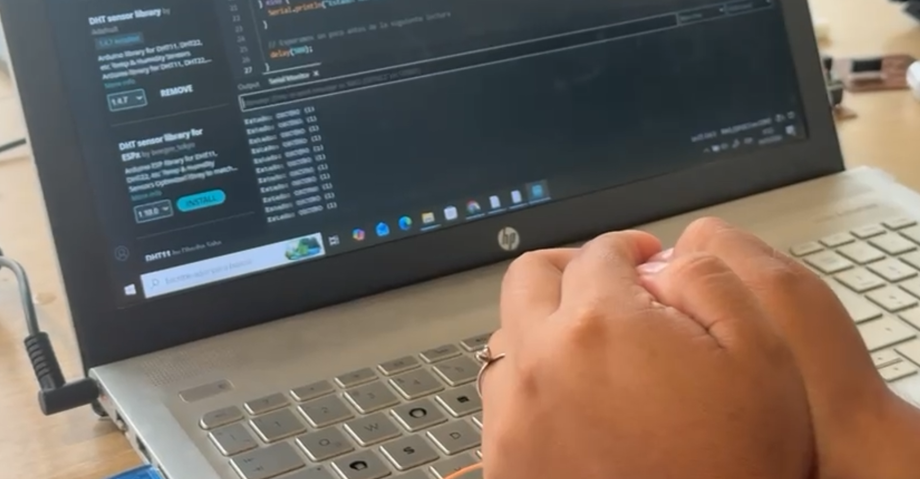
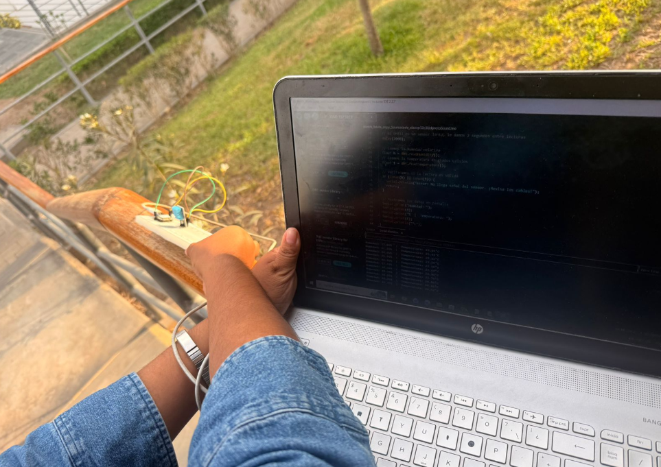
At this stage, I have successfully tested the sensor readings, which are correctly displayed in the serial monitor. However, the servomotors are not yet responding as expected. This suggests that there may be issues related to circuit design, power distribution, or PCB connections.
Despite these challenges, this process has been extremely valuable. It is the first time I have gone through the full workflow of designing, fabricating, and assembling a custom PCB. I learned how to export traces, review geometries in Rhino, prepare files for CNC milling, and perform soldering.
The fabrication process itself required visiting different Fab Labs in Peru, until I was finally able to complete the board at Fab Lab UNI. With the support of instructors and lab staff, I managed to produce a functional prototype that will serve as the base for further testing.
Looking forward, the next steps involve refining the circuit to properly control the servomotors and integrating a solar energy system that allows the device to recharge autonomously. Additionally, I aim to explore wireless communication to enable distributed and adaptive behavior.
Overall, this stage represents the transition from learning individual components to building a coherent system. Even though the prototype is still under development, it establishes a solid foundation for the next iterations of my final project.
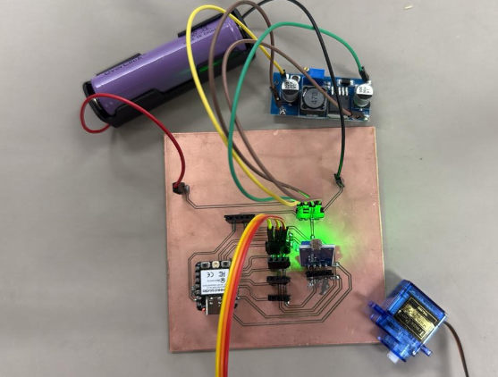
Initial prototype of the final project module and fabrication process.