Assignment Requirements
Group assignment
- do your lab's safety training
- test runout, alignment, fixturing, speeds, feeds, materials, and toolpaths for your machine
Individual assignment
- make (design+mill+assemble) something big (~meter-scale)
- extra credit: don't use fasteners or glue
- extra credit: include curved surfaces
- extra credit: use three-axis toolpaths
Progress Status
Safety training and CNC calibration tests
Design and fabrication of CNC press-fit stool
Uploading fabrication process and files
1) Group Assignment — Distributed Testing (Fab Itinerante)
The group assignment for this week focused on understanding the operational workflow and safety procedures required to work with large-format CNC machines. Before interacting directly with the equipment, it was necessary to complete a formal safety training session that introduced the fundamental protocols required when working in a digital fabrication laboratory.
This activity was organized in two stages. First, the group attended a virtual Lab Safety Training session conducted by the iFurniture laboratory, where the essential safety principles for CNC machining were explained.
After completing the safety training, our Fab Academy cohort held a coordination session through Google Meet. During this meeting we reviewed the next part of the group assignment and organized the distributed workflow that would allow the entire team to follow the CNC demonstration and testing process.
1.1 Lab Safety Training — iFurniture Laboratory
The first step of the assignment consisted of completing the Lab Safety Training. This training session was conducted virtually by the iFurniture laboratory, a digital fabrication space specialized in CNC-based manufacturing technologies.
During the session, the instructors explained the fundamental safety procedures required before operating a CNC router. Unlike smaller digital fabrication machines, large CNC routers use high-speed rotating cutting tools capable of machining dense materials such as plywood or MDF. Because of this, strict safety protocols must always be followed.
The training covered topics such as the proper use of personal protective equipment (PPE), including safety glasses, hearing protection, and appropriate clothing. Participants were also reminded that loose clothing, long hair, or jewelry can represent serious hazards when working close to rotating cutting tools.
Another key topic was the preparation of the working environment. Before any machining operation begins, the CNC workspace must be properly organized. The sacrificial bed must be clean, the material must be securely fixed, and the machine parameters must be verified before starting the cutting process.
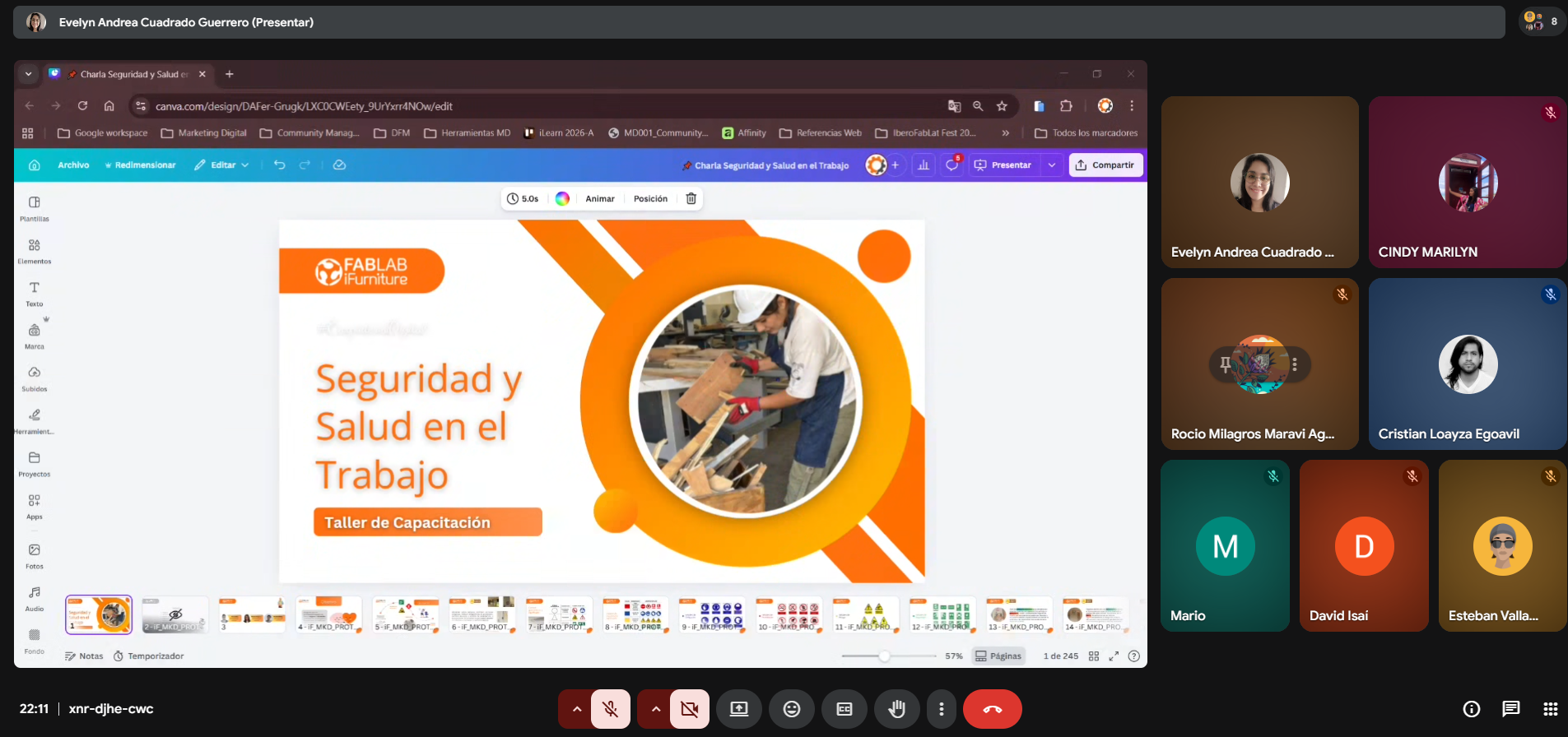
Virtual safety training conducted by iFurniture laboratory.
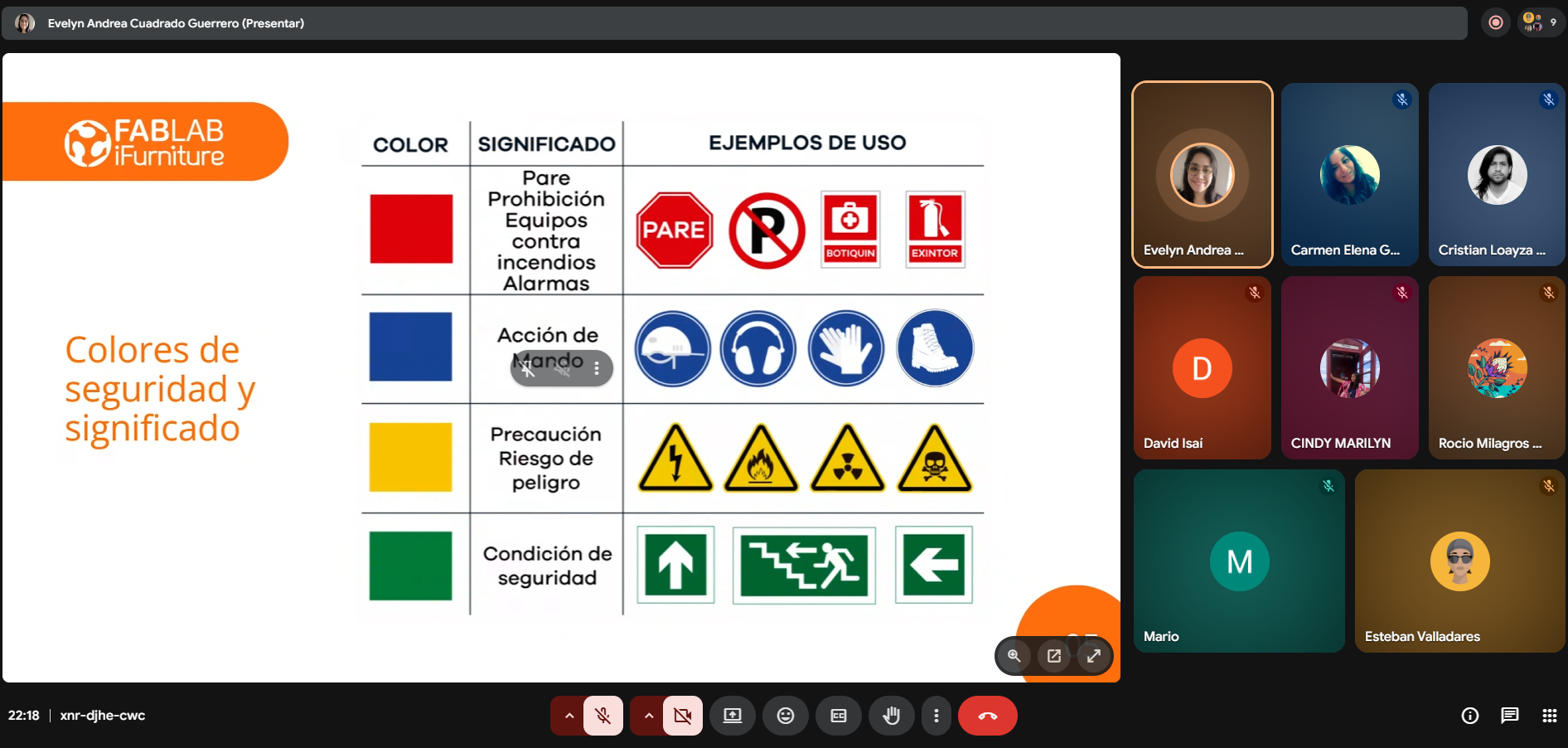
Overview of CNC safety procedures and laboratory protocols.
1.2 Distributed Session — Google Meet Coordination
After completing the safety training, the Fab Academy group held a coordination session through Google Meet in order to prepare the next stage of the assignment. This meeting allowed the entire team to review the workflow of the CNC machine demonstration and organize how the documentation would be carried out.
Because the Fab Academy program in Peru operates through the Fab Itinerante distributed fabrication model, the group participated from different locations while maintaining real-time communication through the online meeting.
During this session, the team was divided into two working groups. Part of the group attended the demonstration physically at Fab Lab UNI in Lima, where they could directly interact with the CNC machine and observe the calibration process.
- Grace, Jian Franco, Carmencita, David and Cindy were physically present at Fab Lab UNI, where they participated in the CNC machine demonstration and performed the calibration tests.
- Esteban, Mario and Rocío participated remotely through Google Meet from their respective laboratories, observing the process and documenting the workflow while the tests were being carried out in Fab Lab UNI.
This hybrid configuration allowed the entire group to follow the CNC testing process even though not all participants were located in the same physical laboratory. Through real-time communication and shared documentation, all members of the group were able to observe the machine setup, understand the calibration procedures, and analyze the workflow required to operate the CNC router safely.
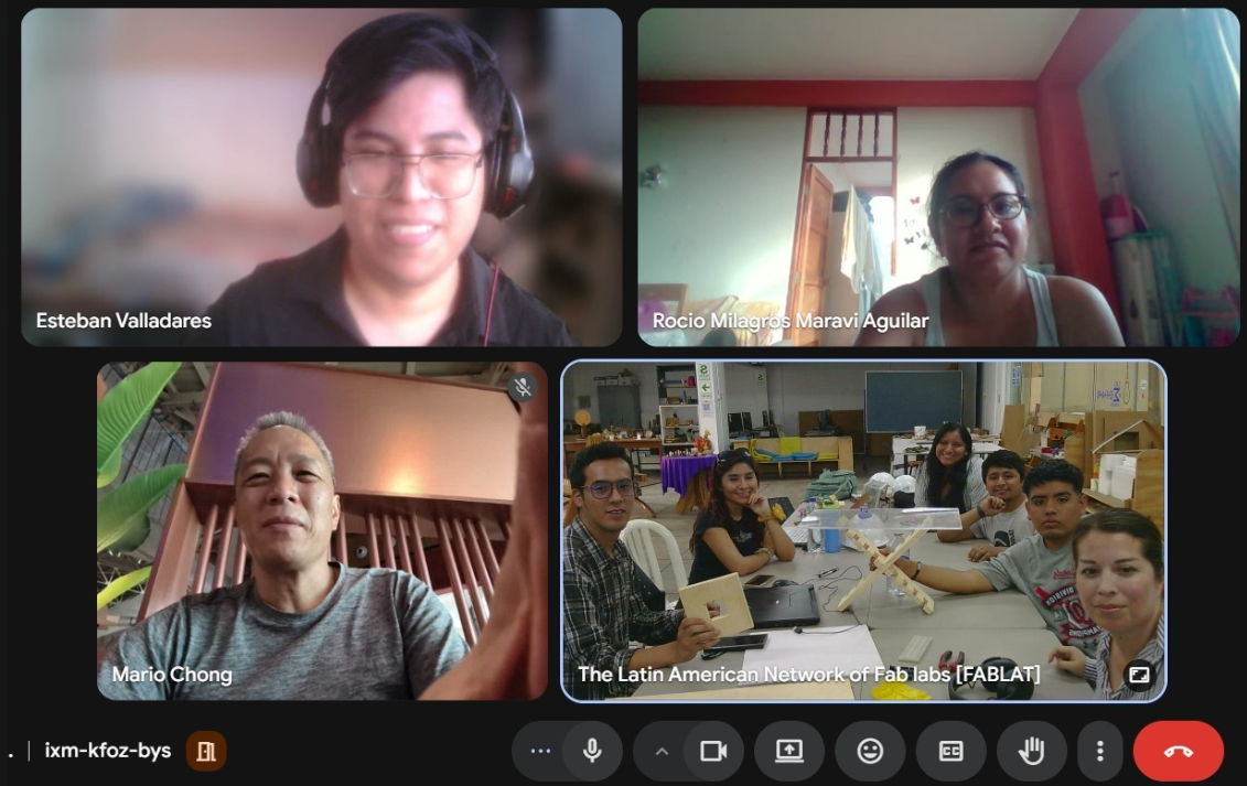
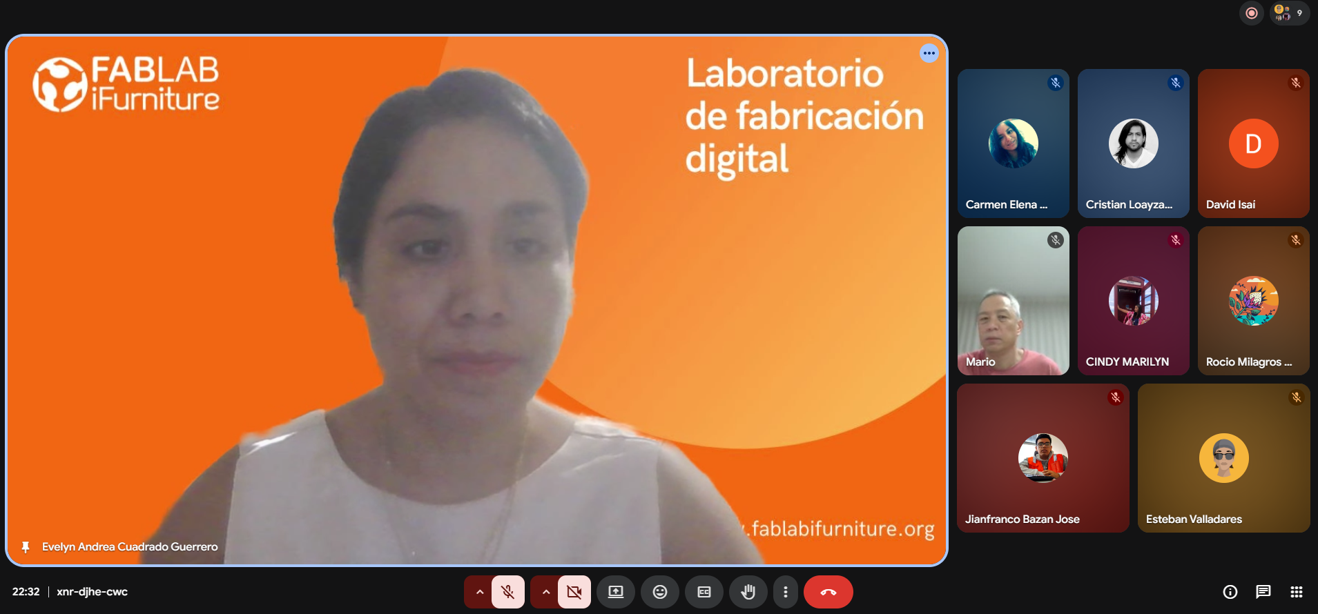
Fab Academy distributed collaboration session via Google Meet.
3) Equipment and Materials
For the practical component of this week's group assignment, the CNC calibration tests and machining demonstrations were performed at Fab Lab UNI in Lima. The laboratory is equipped with large-format CNC routers designed for cutting wood-based materials such as plywood, MDF, and OSB boards.
The purpose of this exercise was not only to observe the operation of the machine, but also to understand how several key machining parameters affect the final fabrication result. These parameters include machine alignment, spindle speed, feed rate, toolpaths, material fixation, and cutting tolerances.
During the demonstration, the team working on-site at Fab Lab UNI prepared the machine and conducted a series of calibration tests designed to evaluate press-fit tolerances and the behavior of plywood during CNC machining.
CNC Router Used
The machining tests were carried out using a large-format CNC router installed at Fab Lab UNI. CNC routers operate by moving a rotating cutting tool along three axes (X, Y, and Z) following toolpaths generated from digital design files.
The spindle rotates the cutting bit at high speed while the machine moves across the material sheet, removing material layer by layer. This subtractive process allows large panels to be cut with high precision and repeatability.
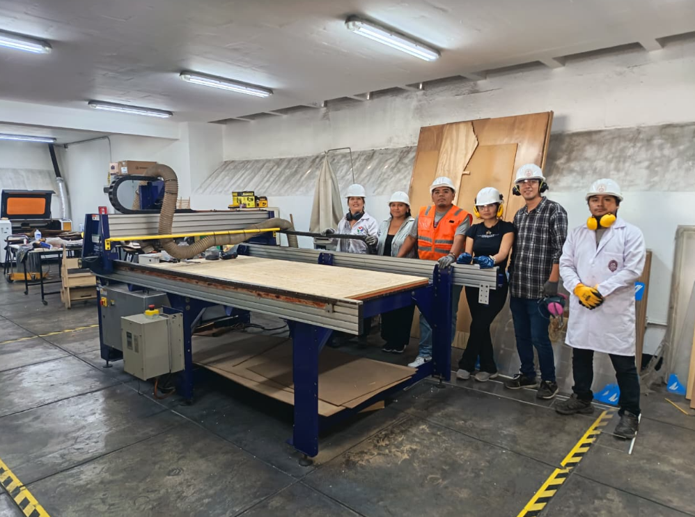
Large-format CNC router used during the group assignment.
Working area and sacrificial bed of the CNC router.
Materials Used
For the calibration tests, the group used plywood sheets commonly employed in digital fabrication and furniture prototyping. Plywood is composed of multiple layers of wood veneer glued together with alternating grain directions, which improves structural stability but can also produce splintering during machining.
Because of this layered structure, the behavior of plywood during CNC cutting depends on several factors including tool sharpness, feed rate, spindle speed, and the direction of the cutting path.
Understanding how the material reacts to the cutting tool is an essential step when designing press-fit joints and structural components fabricated with CNC routers.
4) Safe Workspace and Machine Preparation
Before starting any machining process, the workspace must be carefully prepared. CNC routers operate with high-speed cutting tools and large moving parts, which means that maintaining a safe working environment is essential.
During the demonstration at Fab Lab UNI, the operators verified several safety conditions before starting the machine.
- Ensuring the workspace was clear of obstacles
- Checking that the sacrificial bed was clean
- Confirming that the material sheet was correctly positioned
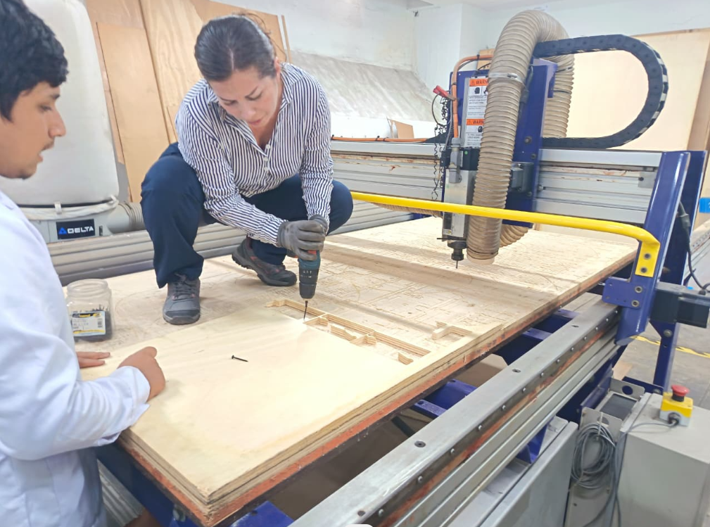
- Securing the material to the bed using screws
- Verifying the emergency stop system
- Confirming that all participants were wearing PPE
These preparation steps help prevent accidents and ensure that the machine can operate safely during the cutting process.
Preparing the CNC workspace before machining.
Material sheet fixed to the CNC bed using screws.
5) Press-Fit Calibration Tests
One of the most important aspects of CNC fabrication is understanding how press-fit joints behave when cut from sheet materials. Because the diameter of the cutting tool removes a small amount of material during machining, the final slot width can differ slightly from the digital design.
To evaluate these tolerances, the team produced two calibration tests commonly used in CNC workflows: the square test and the comb test.
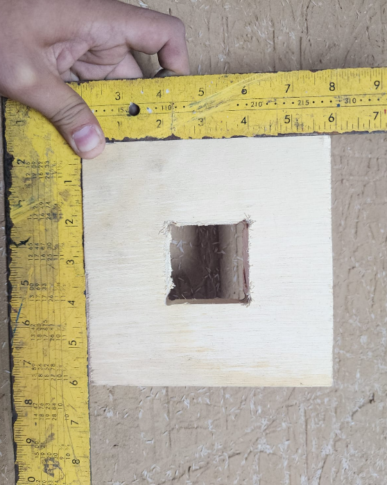
Square Test
The square test was designed to evaluate the internal fitting between two pieces of material. The design consisted of a 150 mm × 150 mm external frame with a 50 mm internal square cutout.
Dogbone fillets were added to the internal corners in order to compensate for the circular geometry of the milling bit. Without these fillets, the internal corners would remain rounded, preventing square parts from fitting correctly.
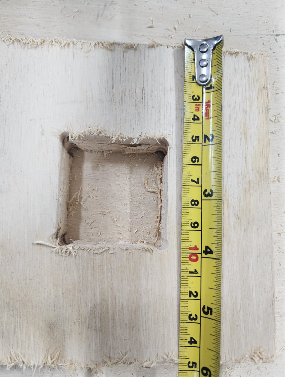
Square press-fit calibration test with dogbone corners.
Comb Test
The comb test was used to compare different slot widths and determine the optimal press-fit tolerance for the material. This test included a series of slots ranging from 18 mm to 20 mm with incremental variations.
By inserting pieces of plywood into each slot, it becomes possible to identify which dimension produces the best press-fit joint without requiring screws or adhesives.
Comb test used to determine press-fit tolerances.
6) Problems and Observations
During the CNC calibration tests, the machining process was completed without major mechanical failures such as tool breakage or material detachment. However, several observations were made regarding the behavior of the plywood material during machining.
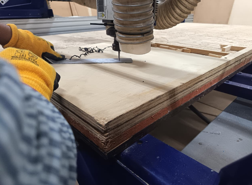
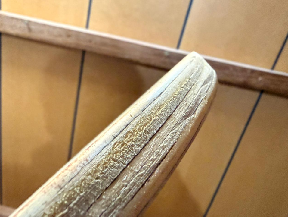
One of the most noticeable effects was the rough edge finish produced during the cutting process. This is a common behavior when machining plywood because the material is composed of multiple layers of wood veneers with alternating grain directions. When the milling bit cuts through these layers, small splinters may appear along the edges.
Another important observation was related to the machine calibration process. After placing the material sheet and fixing it to the CNC bed using screws, the machine origin needed to be verified again. This additional calibration step is necessary because the position of the material can slightly change when the board is secured to the sacrificial bed.
Rechecking the reference coordinates before starting the cutting process ensures that the toolpaths will align correctly with the design geometry and prevents errors during machining.
Edge quality of plywood after CNC machining.
7) What We Learned as a Group
Through this group assignment, we developed a clearer understanding of the workflow involved in large-format CNC machining. Unlike smaller digital fabrication tools, CNC routers require careful preparation before any cutting operation begins.
As a group, we learned that safe CNC operation starts long before the machine is turned on. Preparing the workspace, verifying the machine configuration, and securing the material sheet are essential steps that directly affect the quality of the final result.
Another important lesson was the role of machining parameters such as feed rate, spindle speed, and cutting depth. These parameters influence not only the efficiency of the machining process but also the surface finish and dimensional accuracy of the cut pieces.
We also observed how press-fit calibration tests help determine the appropriate tolerance for joints fabricated from plywood sheets. Because the real thickness of plywood can vary slightly from the nominal value, calibration tests such as the square test and comb test are essential when designing assemblies intended to fit without screws or adhesives.
Overall, this exercise allowed the group to understand how digital design decisions, machine parameters, and material properties interact during the CNC fabrication process.
8) Conclusion
The group assignment for Week 07 provided an introduction to the complete workflow of computer-controlled machining using a large CNC router. Through the safety training session, machine preparation, and calibration tests, we were able to observe how digital designs are translated into physical components through subtractive manufacturing processes.
The press-fit calibration tests demonstrated the importance of understanding machining tolerances and material behavior when designing joints for CNC fabrication. Even small variations in material thickness or tool diameter can significantly affect the assembly of parts.
This experience helped the group understand that CNC fabrication is not only about sending a design file to a machine, but about carefully controlling each stage of the fabrication process—from machine setup and parameter selection to material preparation and post-processing.
9) Individual Assignment
For the individual assignment of Week 07, the objective was to design and fabricate a large object using CNC machining. However, before documenting the final press-fit object developed for this assignment, I would like to briefly present some of my previous experience working with CNC fabrication tools.
During the past year I have collaborated on different experimental projects related to digital fabrication together with architect Conrad San Román as part of the Wisnu project. Through this collaboration I had the opportunity to explore different fabrication processes using CNC routers, including furniture prototyping and structural experiments using plywood sheets.
One of the most interesting prototypes developed during this process was a CNC-fabricated bicycle structure. This project allowed us to experiment with press-fit assemblies, structural components, and large-scale digital fabrication workflows.
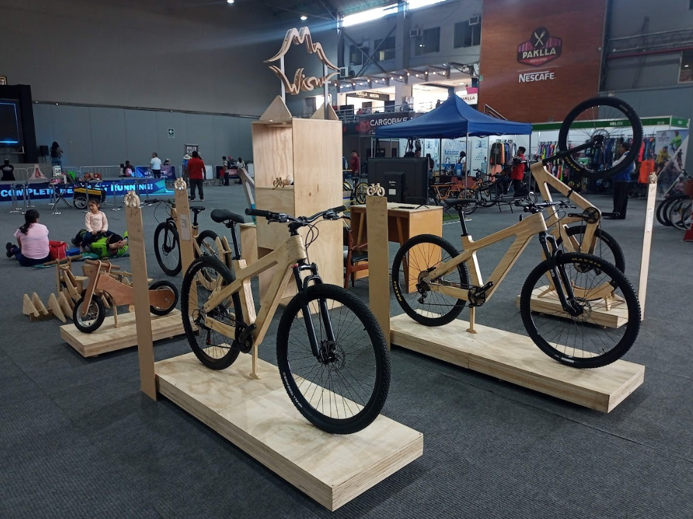
CNC fabrication experiments developed as part of the Wisnu project.
9.1 CNC Experiment — Go-Kart Steering Wheel
As part of the ongoing experiments within the Wisnu project, a small steering wheel component was recently designed and fabricated for a go-kart prototype. This element served as a practical opportunity to explore the complete workflow from digital design to CNC fabrication.
The steering wheel was modeled and prepared using Fusion 360, where both the CAD modeling and the CAM toolpath generation were developed. This workflow allowed the design to be directly translated into machining instructions for the CNC router.
9.1.1 CAD Design in Fusion 360
The design process began by creating a parametric sketch in Fusion 360 defining the general geometry of the steering wheel. The sketch established the circular structure of the wheel and the internal cutouts that would reduce material weight while maintaining structural rigidity.
Once the sketch was defined, the geometry was extruded to create the three-dimensional model of the steering wheel. Fillets were added along the edges to improve the ergonomics of the component and create smoother transitions between surfaces.
Initial sketch used to define the steering wheel geometry.
9.1.2 CAM Setup and Toolpaths
After completing the CAD model, the design was prepared for machining using the CAM workspace in Fusion 360. The CAM setup defines the material dimensions, the origin point of the machine, and the toolpaths that will guide the CNC router.
For this project, three main machining operations were used to fabricate the steering wheel component.
- 2D Contour — used to cut the internal shapes and outer perimeter of the steering wheel.
- Pocket operation — used to machine a circular recess designed to house a mechanical component that would later be fixed using screws.
- 2D Contour finishing pass — executed with a chamfer bit to generate beveled edges around the entire piece, improving both the aesthetic finish and the tactile quality of the component.
Once the toolpaths were configured, Fusion 360 generated a simulation of the cutting process that allowed the tool movement to be visualized before sending the file to the CNC router.
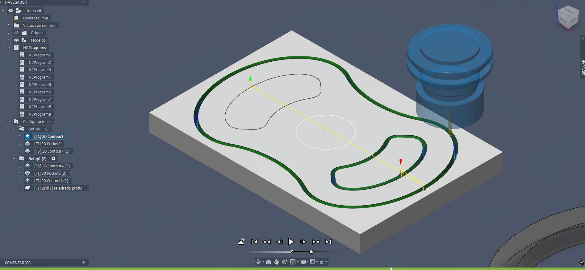
CAM simulation showing the toolpath movement of the milling bit.
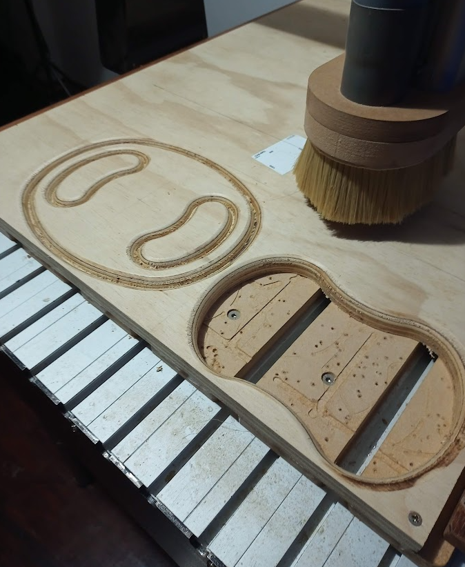
9.1.3 Fabrication Result
After generating the machining program, the file was exported and sent to the CNC router for fabrication. The cutting process followed the programmed toolpaths, gradually removing material from the plywood sheet until the steering wheel component was fully machined.
The final piece was then integrated into the go-kart prototype, demonstrating how digital fabrication workflows can rapidly translate digital designs into functional mechanical components.
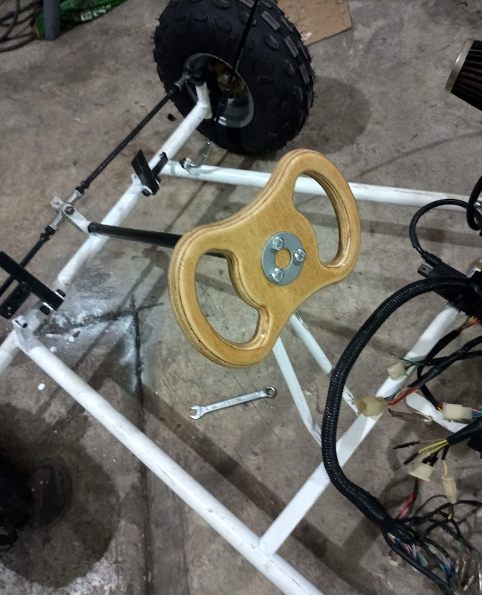
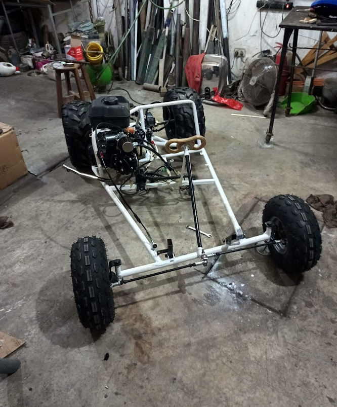
Final steering wheel component installed in the go-kart prototype.
9.2 CNC Press-Fit Stool
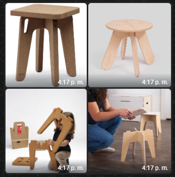
For the official individual assignment of Week 07, the goal was to design and fabricate a larger object using CNC machining. For this exercise I decided to design a small press-fit stool that could be assembled without using screws or adhesives.
The project was intentionally kept simple in order to focus on the principles of CNC fabrication and press-fit assembly. The stool is composed of several interlocking pieces that fit together through slot joints, allowing the structure to be assembled manually after machining.
The main objective of this exercise was to explore how digital design decisions translate into physical assemblies when working with CNC machining and sheet materials.
9.2.1 Design Process
The design of the stool was developed using a combination of CAD tools including Rhino and AutoCAD. The goal was to create a compact structure composed of several flat pieces that could be cut from a plywood sheet and later assembled using press-fit connections.
Each component of the stool was designed considering the thickness of the material that would be used during fabrication. Because the plywood sheet has a nominal thickness of 18 mm, the slots for the press-fit joints were designed slightly larger in order to allow the pieces to fit together more easily during assembly.
For this reason, the slot width was defined as approximately 19 mm, introducing a tolerance of about 0.5 mm on each side. This small clearance helps compensate for material imperfections and ensures that the parts can be assembled without excessive force.
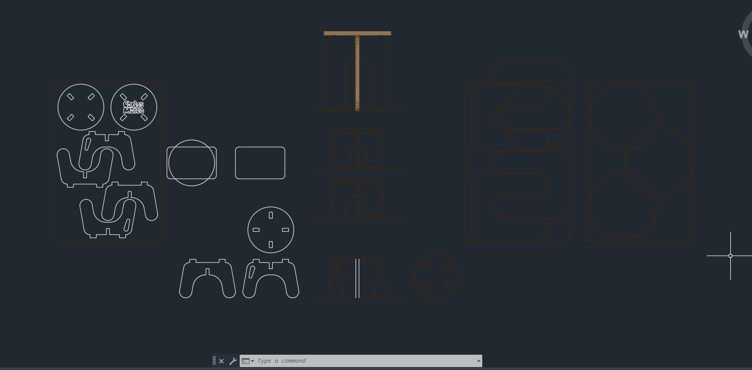
Digital design of the press-fit stool components.
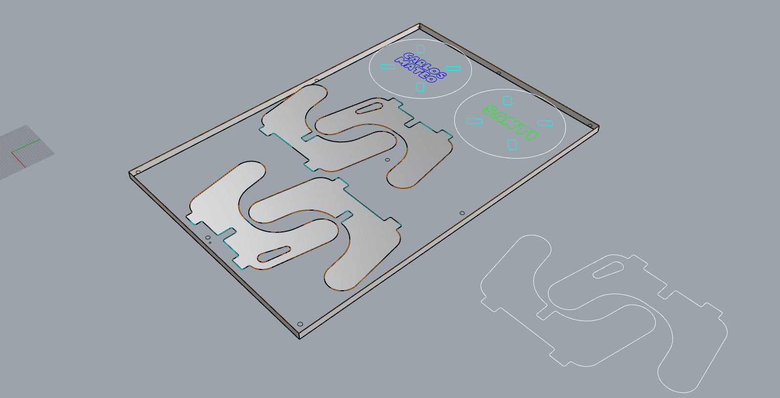
9.2.2 CNC Fabrication
The fabrication process was carried out using a CNC router available at the laboratory. The material used for this assignment was an 18 mm phenolic plywood sheet, which is commonly used in furniture fabrication because of its strength and dimensional stability.
Once the design was prepared, the toolpaths were generated and the cutting file was sent to the CNC machine. The router then followed the programmed toolpaths to cut the individual parts of the stool from the plywood sheet.
After the machining process was completed, the pieces were removed from the board and prepared for assembly.
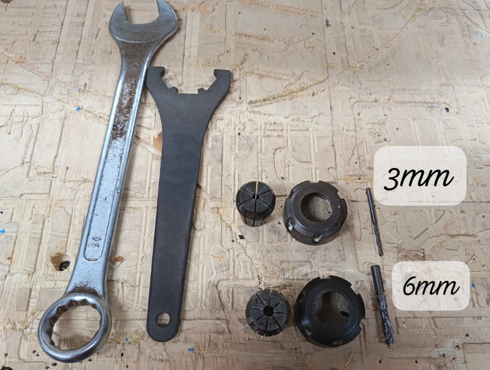
Round Finish
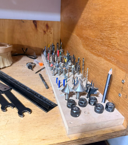
CNC Tools
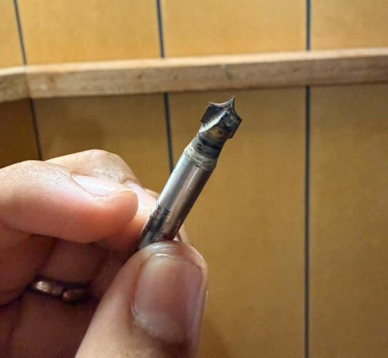
Round tool
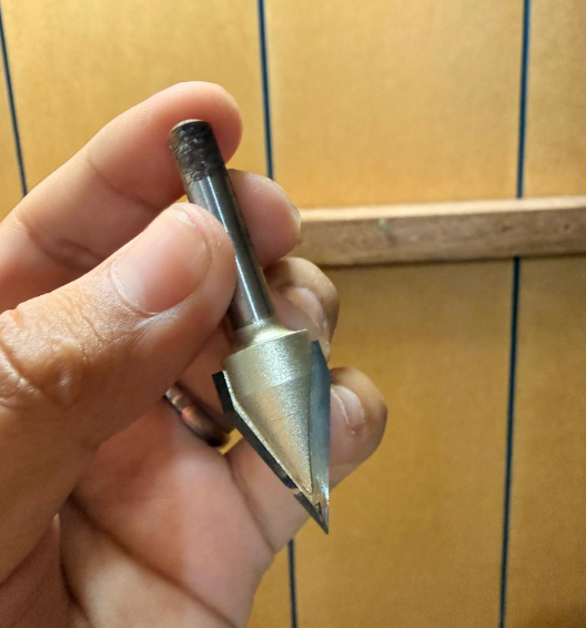
V Tool
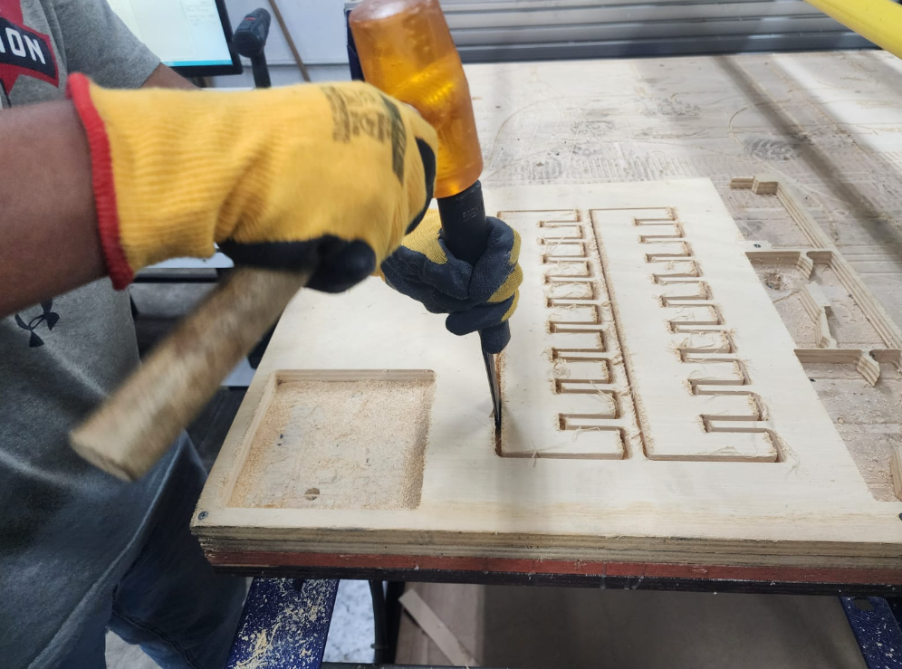
9.2.3 Assembly and Unexpected Issue
During the assembly stage, the pieces were manually inserted into the press-fit slots. Although the tolerances had been considered during the design stage, one of the joints experienced excessive stress while being inserted.
As a result, one of the connections partially fractured during the assembly process. This situation highlighted how small variations in material thickness or cutting precision can affect press-fit assemblies.
Despite the fracture, the components were still able to be assembled and the structure of the stool remained stable.

Press-fit joint showing minor fracture during assembly.
9.2.4 Final Result
After adjusting the pieces and completing the assembly, the stool structure was successfully completed. Even though one of the joints had experienced a small fracture during assembly, the overall structure remained functional.
This final result demonstrates how CNC machining allows digital designs to be transformed into functional furniture prototypes using relatively simple fabrication workflows.
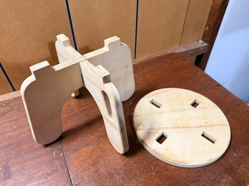
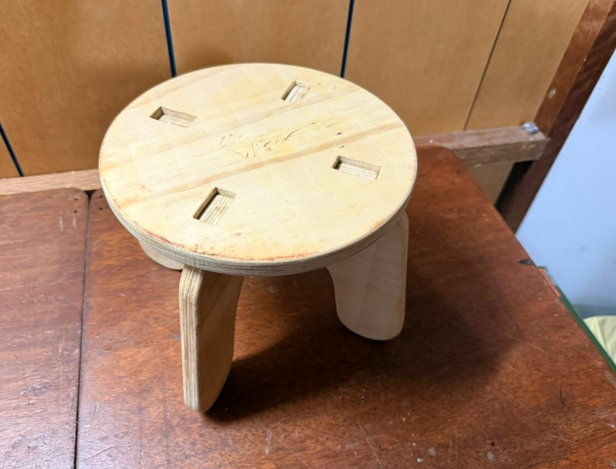
Final assembled press-fit stool.
10) Reflection
This week allowed me to better understand the complete workflow behind large-scale digital fabrication using CNC machines. Unlike smaller fabrication tools such as laser cutters or desktop milling machines, CNC routers operate at a different scale and require a much more careful preparation process.
One of the most important lessons from this assignment was the relationship between digital design and material behavior. Even when a design appears correct in CAD software, real-world factors such as material thickness, tool diameter, and machining tolerances can affect the final result.
The press-fit stool experiment demonstrated how small variations in material properties can influence the assembly process. Designing slots with an appropriate tolerance is essential to ensure that parts can be assembled without damaging the structure.
Another valuable aspect of this week was the opportunity to connect the assignment with my previous experience working with CNC fabrication in the Wisnu project. Through those experiments I had already explored how digital fabrication tools can be used to prototype structural components and furniture elements.
Overall, this week reinforced the idea that CNC fabrication is not only about machining geometry but also about understanding how digital workflows, machine parameters, and material behavior interact during the fabrication process.
11) Files
The following files correspond to the digital designs and resources developed during this week's assignment. These files include the CAD models used to generate the CNC toolpaths as well as the design files for the press-fit stool prototype.
- Group Assignment Download DXF File
- Press-Fit Stool Design Download DXF File
- Press-Fit Stool Rhino Model Download Rhino File (.3dm)
All files are provided for educational purposes and to document the fabrication workflow developed during Fab Academy Week 07.