Assignment Requirements
Group Assignment
- Test the design rules for your 3D printer(s)
Individual Assignment
- Design and 3D print an object that cannot be made subtractively
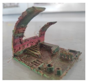
- 3D scan an object (and optionally print it)
1) Group Assignment — Distributed Design Rule Testing (Fab Itinerante)
The group assignment for this week consisted of testing and characterizing the design rules of different FDM 3D printers. Rather than working in a single shared laboratory, we developed this assignment under a distributed fabrication model as part of the Fab Itinerante initiative.
Each member carried out the tests in their respective fabrication environment, located in different regions of Peru. This decentralized approach reflects the core philosophy of the Fab Lab network: local production combined with shared digital collaboration and standardized documentation.
Distributed Fabrication Context
The printers were tested in the following locations:
- Carmen — Fab Lab Koajika Satipo, Satipo (Amazonía del Perú)
- David — Fab Lab Museo de Arqueología, Pueblo Libre (Lima)
- Esteban — Personal workshop (home-based fabrication environment)
- Jean Franco — Fab Lab UNI
- Cindy — Independent Fab Lab workspace
- Rocío — Fab Lab ESAN
Because of this distributed structure, we did not gather physically in a single Fab Lab. Instead, we coordinated virtually to define which test each member would conduct, ensuring that all critical fabrication variables were evaluated across the group.
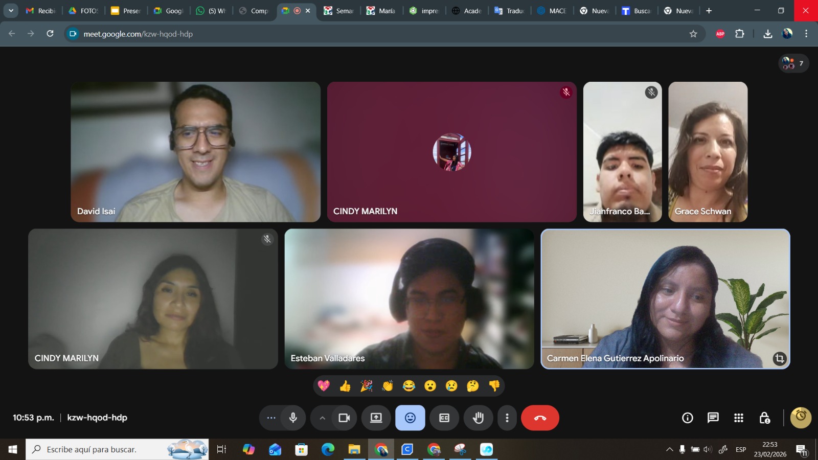
Virtual coordination session — defining test distribution and documentation strategy.
Test Distribution Strategy
To ensure meaningful comparison, we divided the design rule tests among participants. Each person focused on specific stress conditions that reveal mechanical, thermal, or dimensional limits of FDM fabrication:
- Carmen: Calibration cube (X/Y/Z verification) and structural stress kit testing.
- David: Overhang testing (normal vs tree supports) and clearance evaluation.
- Esteban: Anisotropy test, surface finish evaluation, and angle performance testing.
- Jean Franco: Retraction test and temperature calibration analysis.
- Cindy: Overhang and general support behavior evaluation.
- Rocío: Overhang, angle test, tolerance verification, and infill density comparison.
By distributing the experiments, we generated a broader dataset that reflects how different printer architectures, extrusion systems, slicer workflows, and environmental conditions influence fabrication outcomes.
Why This Matters
Design rule testing transforms fabrication from a trial-and-error process into an evidence-based design strategy. Understanding overhang limits, minimum tolerances, cooling efficiency, and support behavior allows us to design geometries that respect the real constraints of additive manufacturing. This week was not about printing objects — it was about understanding the fabrication logic behind each machine.
3) Technical Comparison of 3D Printers
To better understand fabrication behavior across different environments, we compared the mechanical architecture, extrusion systems, calibration methods, and slicer workflows of each printer involved in the distributed testing.
This comparison moves beyond theoretical manufacturer specifications and focuses on fabrication-relevant parameters that directly affect design rule testing.
| Printer | Architecture | Build Volume | Extrusion System | Leveling | Slicer |
|---|---|---|---|---|---|
| Artillery Genius Pro | Cartesian | 220 × 220 × 250 mm | Direct Drive | Manual | Cura |
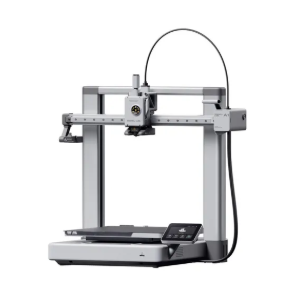
| Creality K1 SE | CoreXY | 220 × 220 × 250 mm | Dual Gear Direct Drive | Automatic | Creality Print |
| Bambu Lab A1 / A1 Combo | Cartesian (High Acceleration) | 256 × 256 × 256 mm | Direct Drive 0.4mm | Full Automatic | Bambu Studio |
| Prusa XL | CoreXY | 360 × 360 × 360 mm | Multi-toolhead | Automatic | Orca / Prusa Slicer |
| Bestgee T300S Pro | Cartesian FFF | Approx. 300 × 300 × 300 mm | Direct Drive | Manual | Cura |
| Bambu Lab A1 | Cartesian | 256 × 256 × 256 mm | Direct Drive | Automatic | Bambu Studio |
Visual Documentation of the Printers
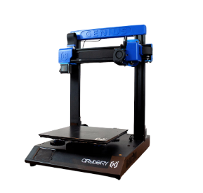
Artillery Genius Pro — Fab Lab Koajika Satipo, Satipo.
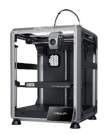
Creality K1 SE — Fab Lab Museo de Arqueología, Lima.
Bambu Lab A1 — Esteban’s personal workshop.
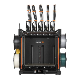
Prusa XL — Fab Lab UNI.
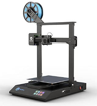
Bestgee T300S Pro — Cindy’s Fab Lab workspace.
Bambu Lab A1 — Fab Lab ESAN.
Comparative Observations
CoreXY systems (Creality K1 SE and Prusa XL) demonstrate higher acceleration and speed performance due to reduced moving mass on the X/Y plane. Cartesian systems, while mechanically simpler, require greater attention to frame rigidity and vibration control.
Automatic calibration systems (Bambu Lab A1 series) significantly reduce setup time and improve first-layer reliability, whereas manual leveling systems require deeper mechanical understanding but allow hands-on tuning.
4) Design Rule Testing — Results by Participant
The distributed fabrication model allowed each participant to test specific fabrication constraints using their assigned printer. Below is a structured summary of the results.
Carmen — Artillery Genius Pro
Calibration cube (X/Y/Z verification) and structural stress testing. Results highlighted the importance of manual bed leveling and extrusion consistency.
David — Creality K1 SE
Overhang testing (normal vs tree supports) and clearance evaluation. CoreXY architecture demonstrated high-speed stability and consistent support removal.
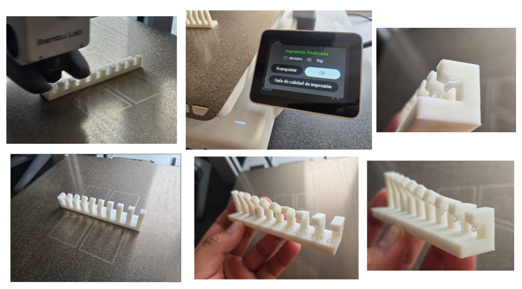
Esteban — Bambu Lab A1 (Personal Workshop)
I conducted anisotropy, angle, and surface finish tests to evaluate dimensional precision, cooling efficiency, and adaptive layer performance.
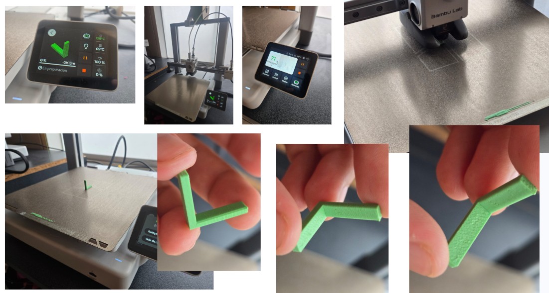
Anisotropy Test
This test analyzed directional mechanical behavior due to layered fabrication. Results confirmed strong inter-layer bonding and consistent Z-axis calibration.
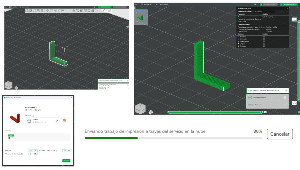
Download Anisotropy Test (.3mf)
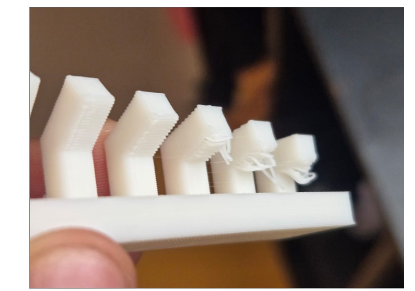
Angle (Overhang) Test
The printer achieved clean unsupported angles up to approximately 20°. Below this threshold, minor sagging was observed.
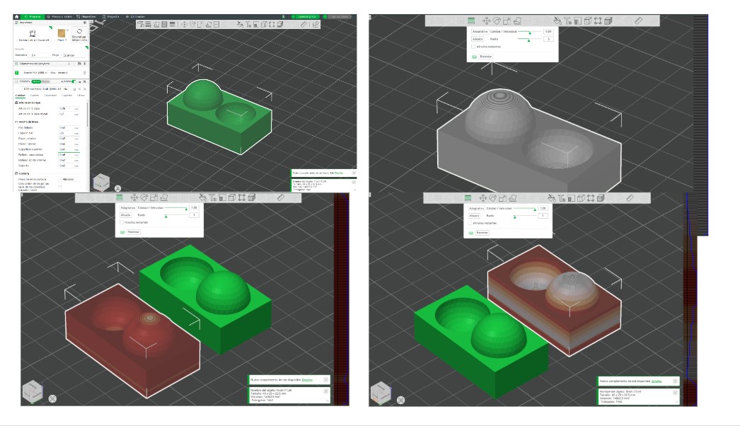
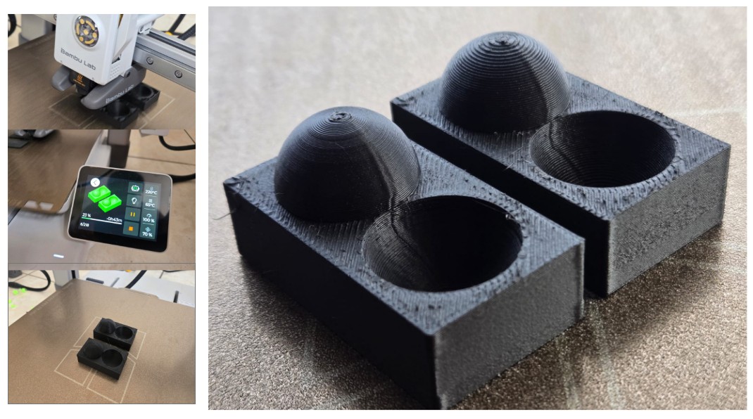
Surface Finish & Adaptive Layering
Adaptive layer height significantly improved curved surface resolution. Two configurations were tested to compare time efficiency vs visual quality.
Jean Franco — Prusa XL
Retraction and temperature calibration testing to analyze stringing behavior and optimal extrusion parameters.
Cindy — Bestgee T300S Pro
Overhang and support behavior testing using Cura. Results emphasized the importance of manual calibration.
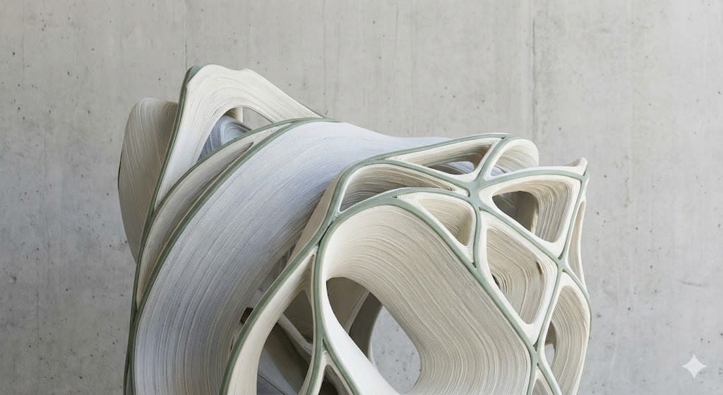
5) Individual Assignment — 3D Scanning to Parametric Voronoi Fabrication
The individual assignment required designing and 3D printing an object that could not be made subtractively, as well as performing a 3D scan. My workflow began with scanning a physical object and evolved into a parametric Voronoi-based transformation process.
5.1 3D Scanning Process — PolyCam Workflow
The scanned object was a small koala souvenir brought by Carmen. The scanning process was performed using the PolyCam mobile application.
Approximately 150 photographs were captured around the object to ensure full surface coverage. The photos were taken from multiple angles and heights to minimize blind spots and mesh distortion.
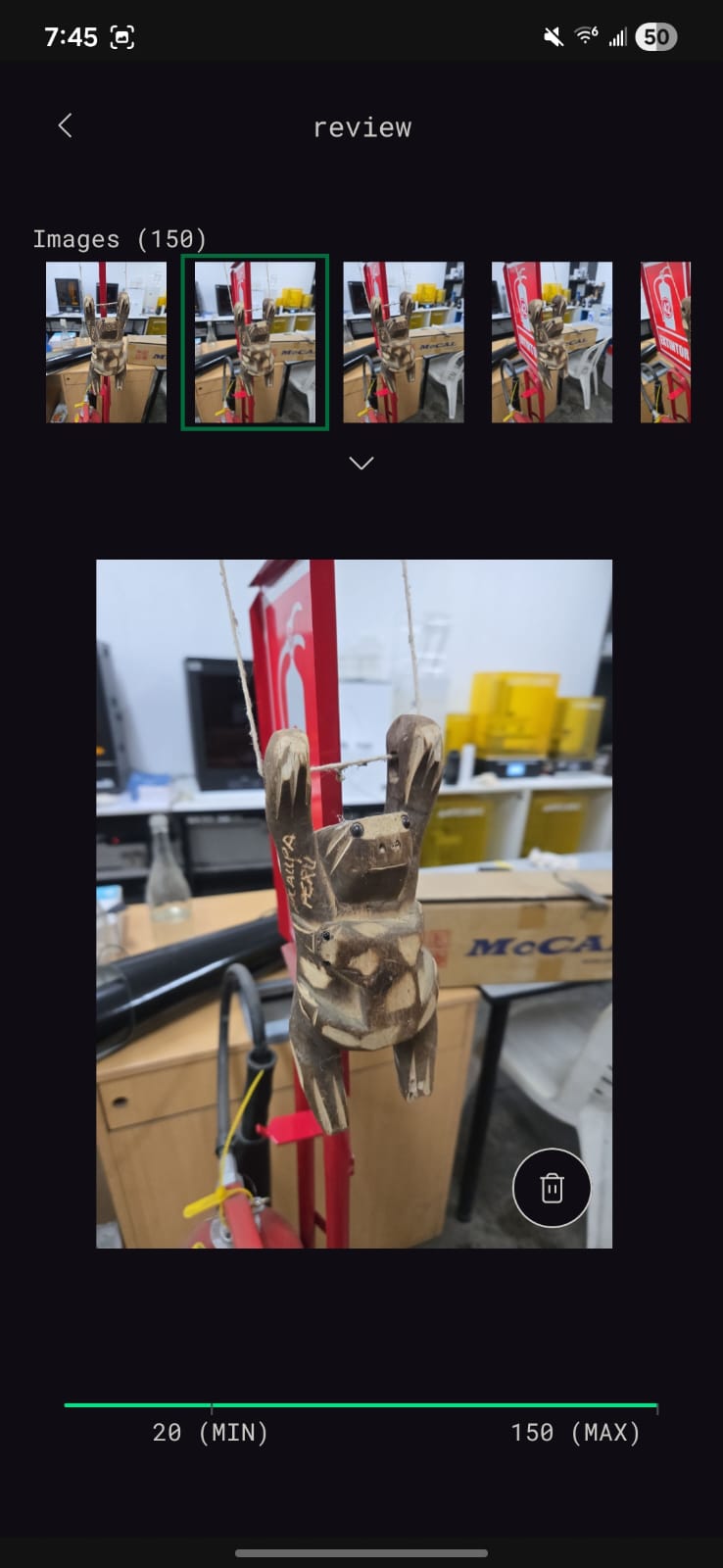
Photo capture stage inside PolyCam.
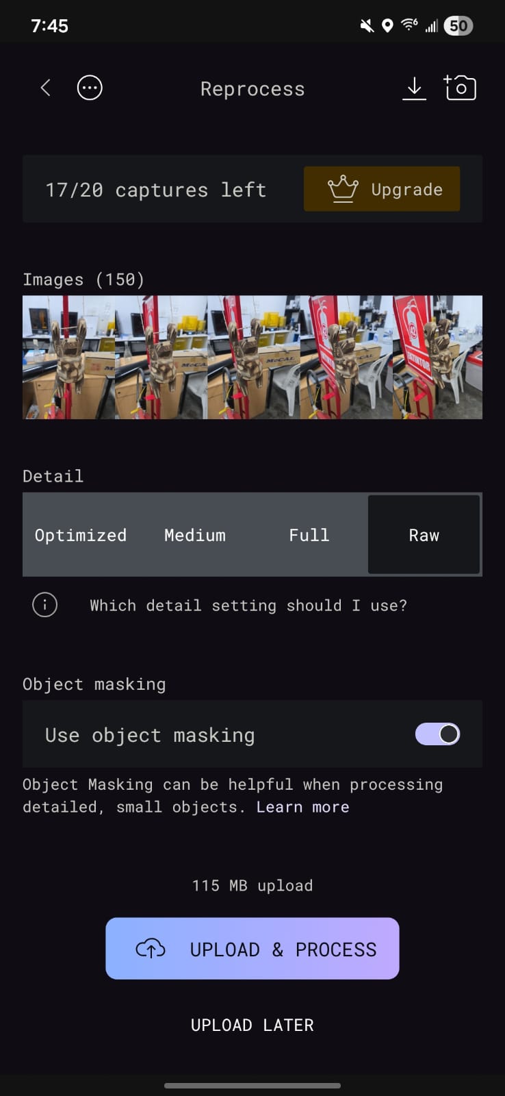
Mesh processing configuration.
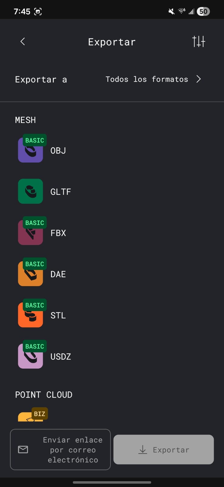
Exporting final GLTF file.
Processing Configuration
After capturing the images, the processing stage required selecting:
- Object Masking: Enabled to isolate the koala from the environment.
- Mesh Quality: Defined according to desired polygon density.
- Cloud Processing: Waited for PolyCam to generate the 3D mesh.
Once processing was completed, the free export format available was GLTF (.gltf).
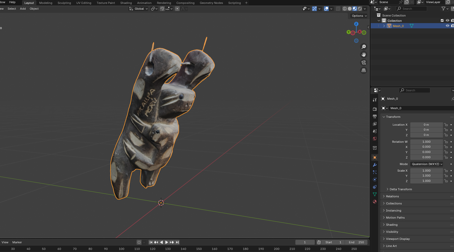
5.2 Blender Workflow — Parametric Voronoi Transformation
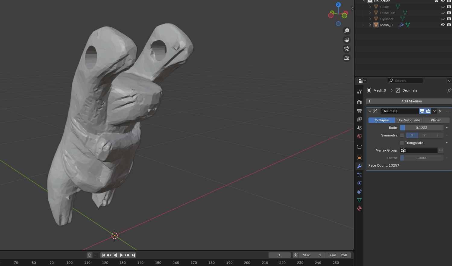
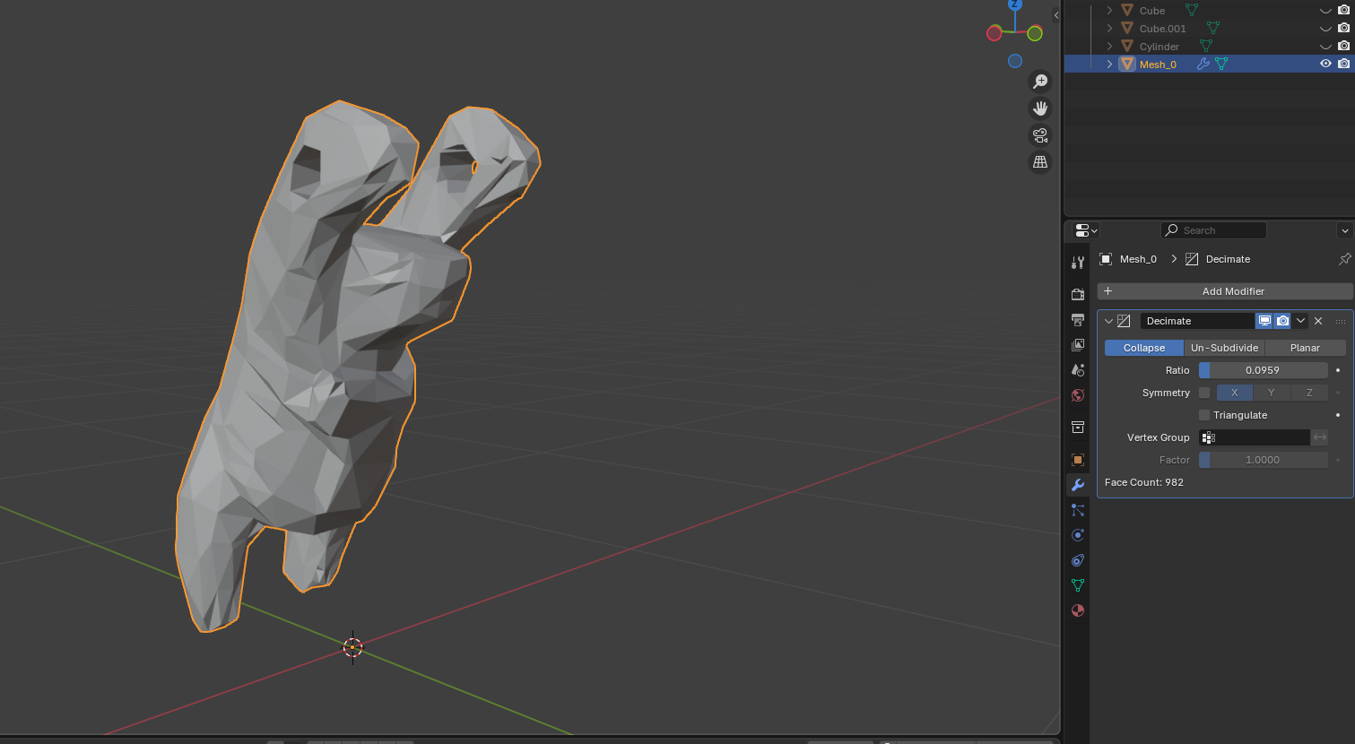
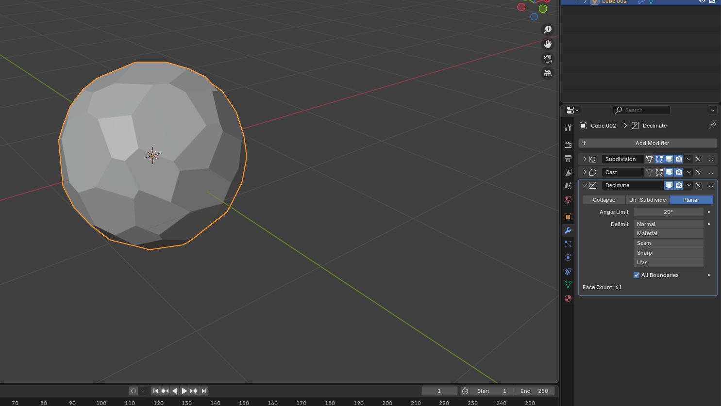
The GLTF file was imported into Blender, where the parametric transformation began. The process consisted of mesh optimization followed by structural abstraction.
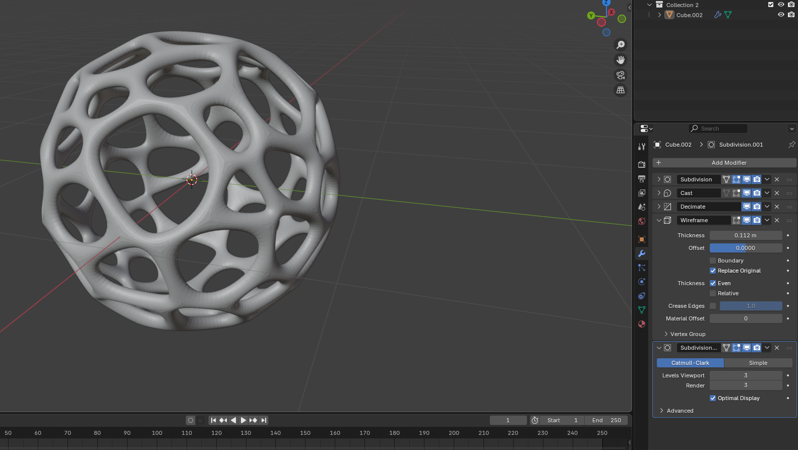
Import GLTF
↓
Apply Decimate Modifier (reduce polygon count)
↓
Apply Wireframe Modifier (generate skeletal structure)
↓
Apply Subdivision Surface (smooth abstraction)
↓
Export STL
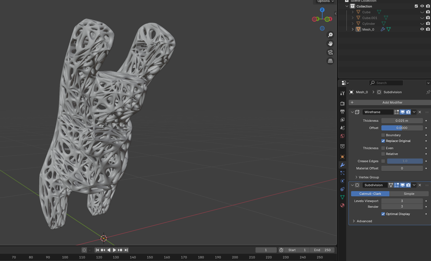
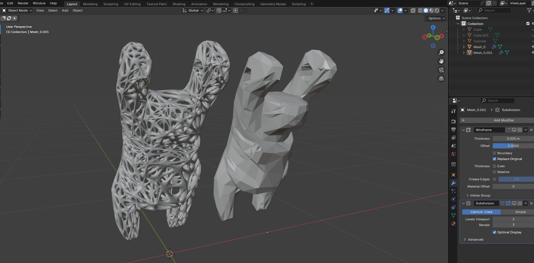
The Wireframe modifier converted the solid mesh into a structural lattice, transforming the figurative koala into a skeletal Voronoi-like abstraction.
Subdivision Surface refined edge transitions, generating a more organic, continuous geometry that emphasizes additive fabrication potential.
Download Blender File (.blend)
5.3 Scaling Adaptation — From Koala to Small Print Object
While the koala-based transformation demonstrated the full parametric workflow, the assignment required printing an object of only a few cubic centimeters.
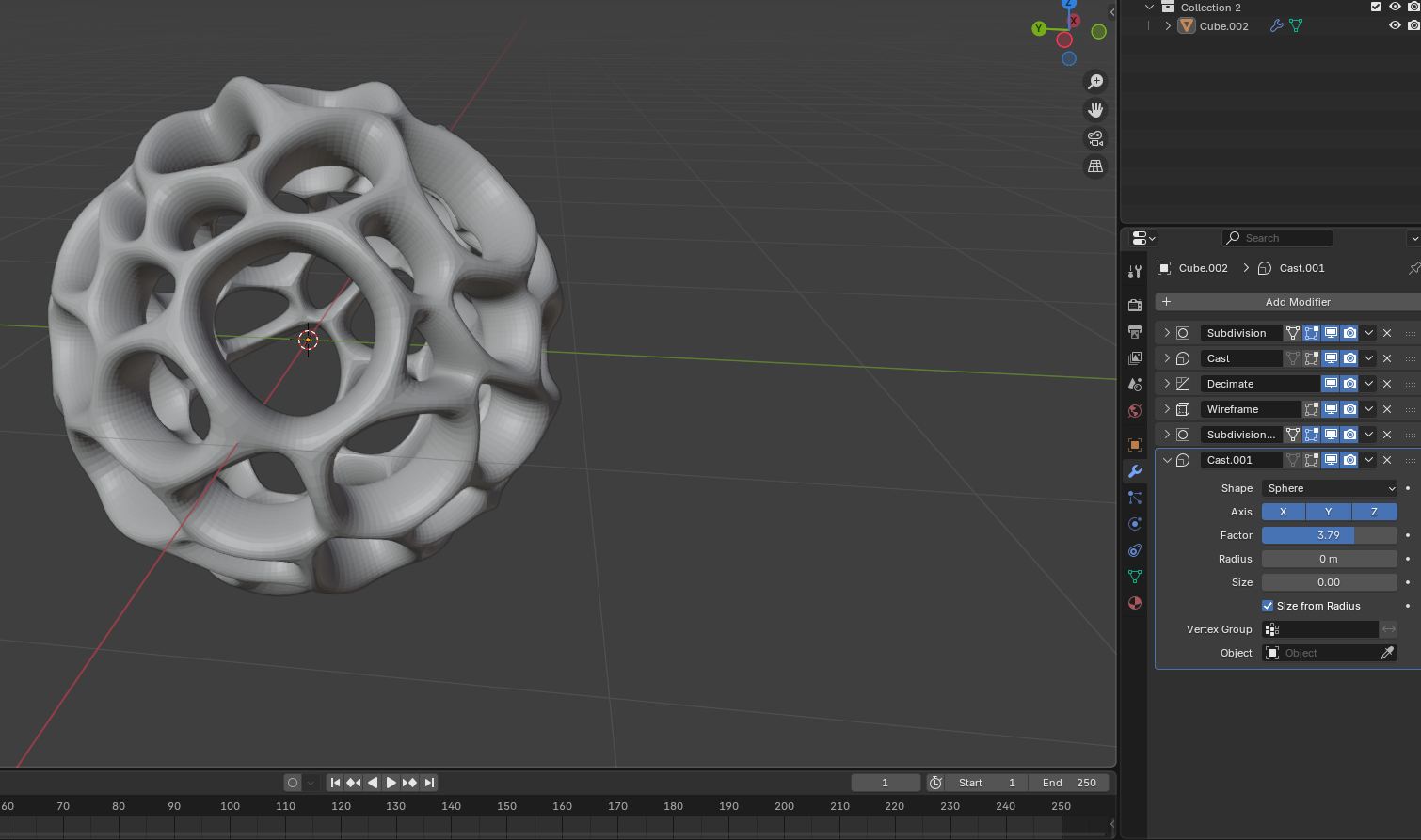
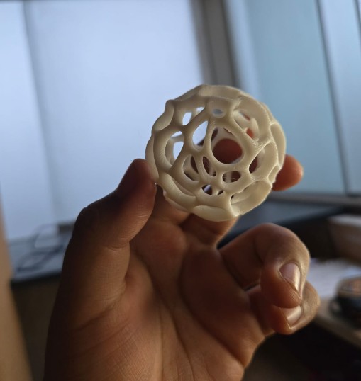
To comply with time and volume constraints, I applied the same Voronoi transformation logic to a smaller spherical base geometry.
This sphere underwent the same modifier sequence:
- Wireframe abstraction
- Subdivision smoothing
- Structural void generation
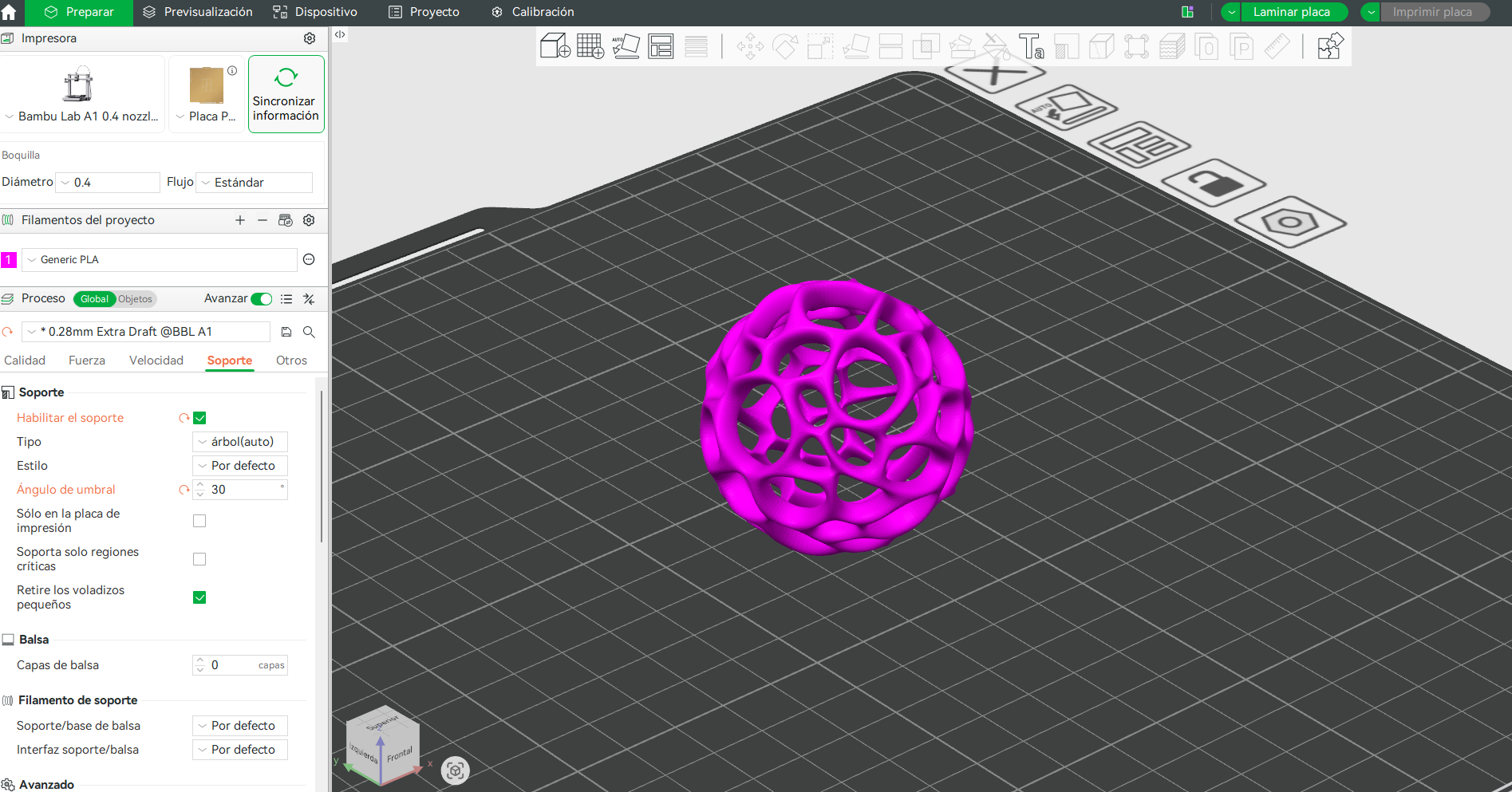
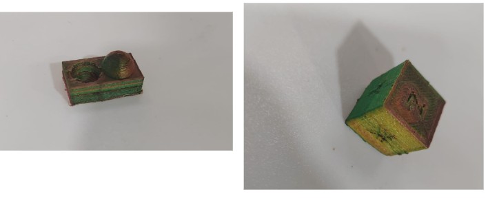
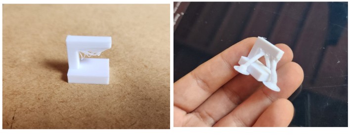
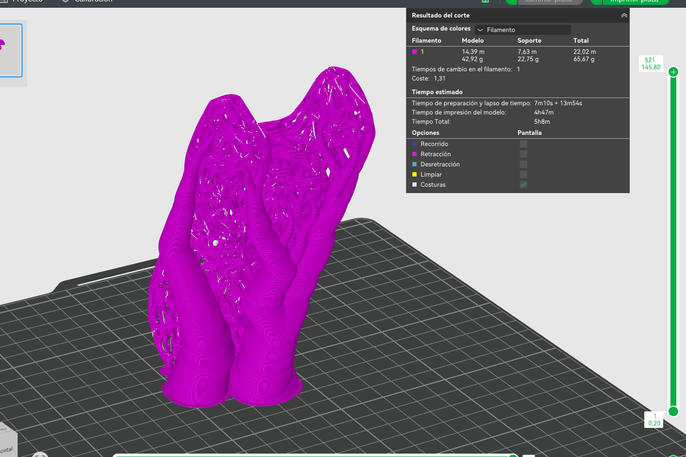
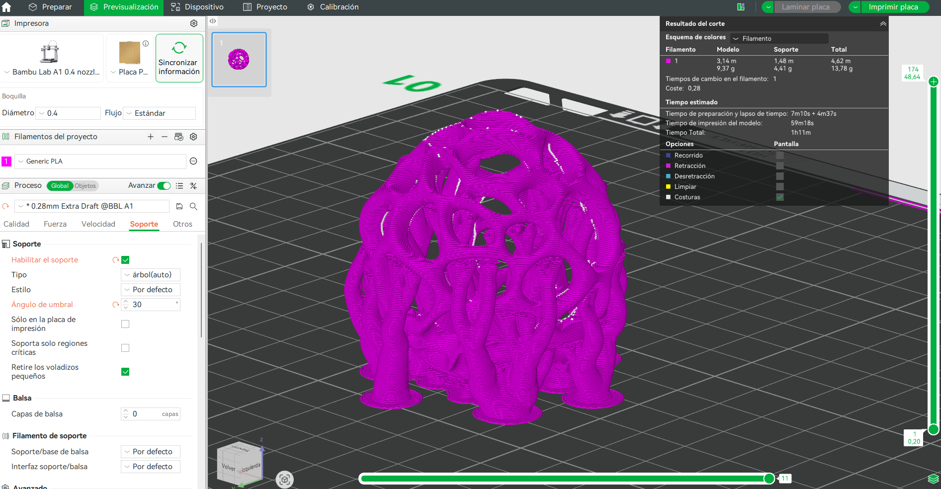
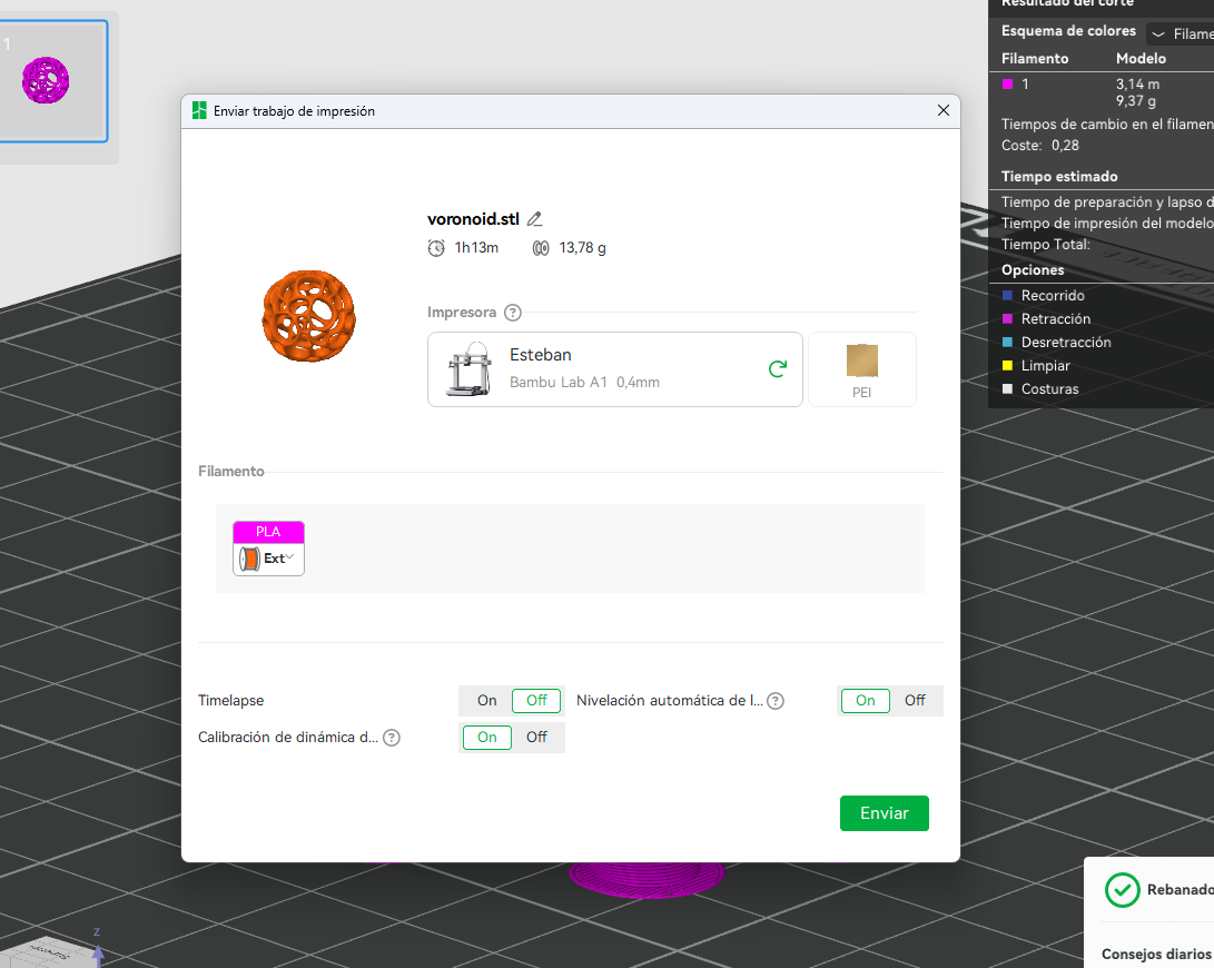
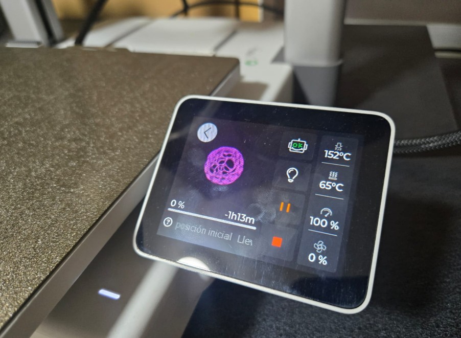
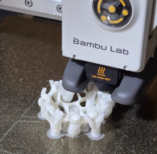
5.4 Final 3D Print — Bambu Lab A1
The final spherical Voronoi structure was printed using PLA on the Bambu Lab A1.
- Print time: ~1 hour
- Supports required
- Layer height: 0.28 mm
- Material: PLA
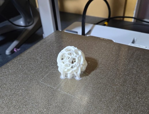
Why This Object Cannot Be Made Subtractively
The final geometry contains continuous internal cavities, undercuts, and multi-directional lattice voids that are inaccessible to milling tools.
Subtractive fabrication would require dividing the object into multiple parts, whereas additive manufacturing allows it to be printed as a single, unified structure.
6) Final Reflection — From Capture to Generative Fabrication
This week shifted my understanding of 3D printing from a prototyping tool to a fabrication logic system. The process of scanning, transforming, and re-fabricating an object revealed how digital geometry can evolve beyond simple replication into generative abstraction.
The koala scan was not merely reproduced; it became the starting point for a parametric transformation. Through the use of modifiers such as Decimate, Wireframe, and Subdivision Surface, the object transitioned from figurative representation to structural lattice.
Technical Learning Outcomes
- Understanding photogrammetry-based mesh generation
- Managing polygon density for printable geometry
- Transforming solid meshes into structural lattices
- Identifying overhang thresholds and cooling limits
- Recognizing additive-specific design opportunities
7) Downloads
The following files document the complete workflow of this week, including design rule testing, 3D scanning, parametric transformation, and final additive fabrication.
Design Rule Testing — Bambu Lab A1
3D Scanning File
Blender Parametric Workflow
Final Printable Geometry
All files are provided to ensure transparency and reproducibility. The .3mf files include slicing configurations specific to the Bambu Lab A1, while the .blend file documents the parametric transformation process.