
Assignment Requirements
Group assignment
- Demonstrate and compare the toolchains and development workflows for available embedded architectures
Individual assignment
- Browse through the data sheet for a microcontroller
- write and test a program for an embedded system using a microcontroller to interact (with input &/or output devices) and communicate (with wired or wireless connections)
- extra credit: assemble the system
- extra credit: try different languages &/or development environments
Group Assignment
Demonstrate and compare the toolchains and development workflows for available embedded architectures.
Group members: Esteban Valladares + JF
1) Objective
The objective of this assignment was to physically program and compare different embedded architectures and their corresponding development toolchains. We analyzed AVR (8-bit), ARM Cortex-M0+ (32-bit), and RISC-V (32-bit) architectures by testing real boards and evaluating their compilation workflows, memory structures, and upload methods.
2) Boards and Architectures Compared
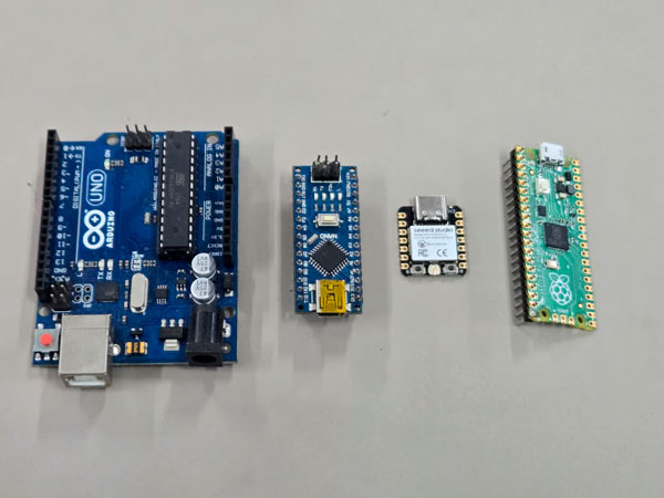
We compared four boards representing three processor families:
- Arduino Uno — ATmega328P (AVR, 8-bit)
- Arduino Nano — ATmega328P (AVR, 8-bit)
- XIAO ESP32-C3 — RISC-V (32-bit)
- Raspberry Pi Pico — RP2040 (ARM Cortex-M0+, 32-bit)
3) Architecture Comparison
| Board | Architecture | Word Size | Clock | WiFi |
|---|---|---|---|---|
| Arduino Uno | AVR (Modified Harvard) | 8-bit | 16 MHz | No |
| Arduino Nano | AVR (Modified Harvard) | 8-bit | 16 MHz | No |
| XIAO ESP32-C3 | RISC-V | 32-bit | 160 MHz | Yes |
| Raspberry Pi Pico | ARM Cortex-M0+ | 32-bit | 133 MHz | No |
4) AVR Toolchain — Arduino Uno / Nano
Toolchain used:
- Arduino IDE
- avr-gcc compiler
- avrdude uploader
- USB bootloader
Workflow:
Write code (.ino)
↓
avr-gcc compilation
↓
Generate .hex file
↓
Upload via USB bootloader
Compilation was very fast and binary size remained small due to limited SRAM and Flash.
5) RISC-V Toolchain — XIAO ESP32-C3
Toolchain used:
- Arduino IDE with ESP32 board package
- riscv32-esp-elf-gcc compiler
- esptool.py flasher
Write code (.ino)
↓
riscv32-esp-elf-gcc compilation
↓
Generate .bin file
↓
Flash to SPI memory
Compilation time was longer due to networking stack integration and larger memory footprint.
6) ARM Toolchain — Raspberry Pi Pico (RP2040)
Toolchain options:
- Arduino Core (arm-none-eabi-gcc)
- MicroPython (UF2 drag-and-drop)
Write code
↓
Compile (arm-none-eabi-gcc)
↓
Generate UF2
↓
Drag & drop to board
The RP2040 offered flexible development, especially with MicroPython experimentation.
7) Demonstration Results
| Board | Compile Speed | Binary Size | Upload Method | Status |
|---|---|---|---|---|
| Arduino Uno | Very Fast | Small | USB Serial | Success |
| XIAO ESP32-C3 | Moderate | Large | USB Native | Success |
| RP2040 | Fast | Medium | UF2 | Success |
8) Reflection
Comparing AVR, ARM, and RISC-V architectures revealed how embedded systems evolve from deterministic minimal controllers to network-enabled computational nodes. As an architecture student, I interpreted memory hierarchies as spatial layers and toolchains as construction workflows. This analogy helped me understand embedded logic as structured and layered systems.
9) Errors & Fixes
- Error: Board not detected. Fix: Installed correct driver and selected proper COM port. Evidence: Serial monitor log.
- Error: ESP32 compile failed. Fix: Installed ESP32 board package and updated libraries. Evidence: Successful compile screenshot.
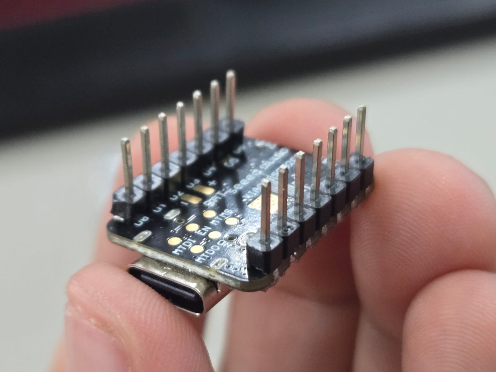
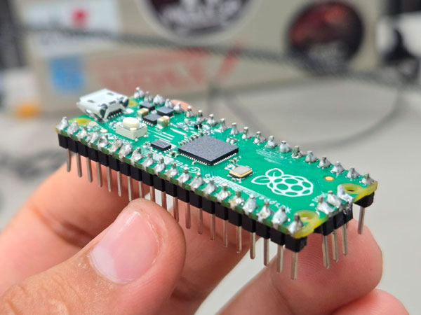
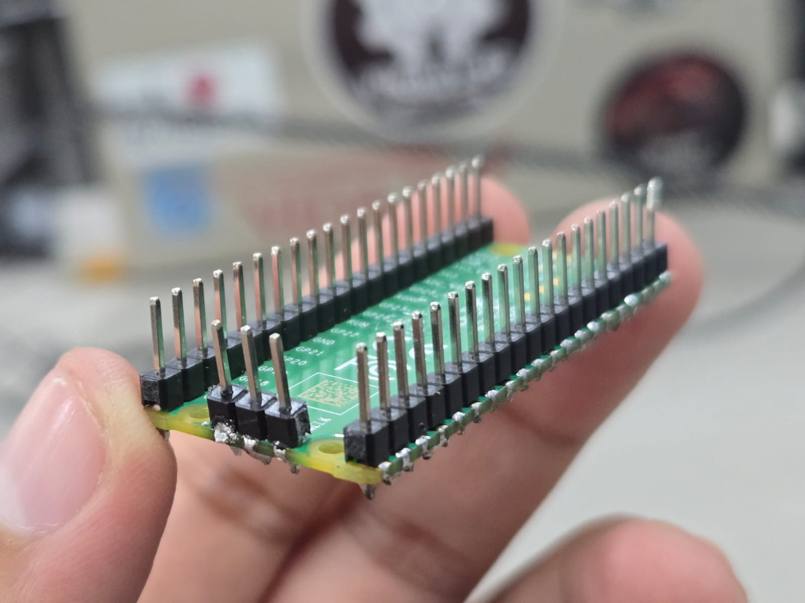
10) Preparation — Soldering the Headers
Before beginning the architectural and toolchain comparison, we needed to prepare our development boards physically. Both the XIAO ESP32-C3 (my board) and the Raspberry Pi Pico (JeanFranco’s board) required soldering header pins in order to connect them to a breadboard for testing.
This was my first time soldering electronic components. Understanding that embedded systems are not only about software but also about physical assembly was an important first step in entering the world of electronics.
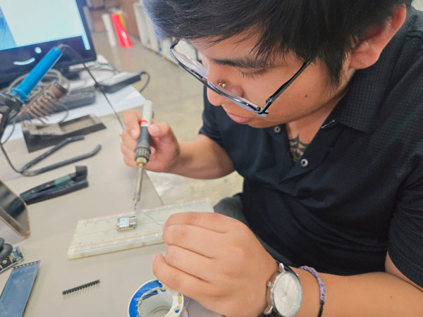
Esteban soldering header pins to the XIAO ESP32-C3 (first soldering experience).
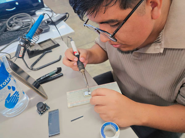
JeanFranco soldering header pins to the XIAO ESP32-C3 and then to the Raspberry Pi Pico (RP2040).
Preparing the boards ourselves helped us understand the physical layer of embedded systems — from silicon architecture to tangible electrical connections. Only after this step were we able to begin programming and comparing development workflows.
11) Demonstration — LED Blink Test
To compare the development workflows across different architectures, we programmed a simple LED Blink test on each board. This allowed us to verify compilation, binary generation, upload method, and runtime execution.
Arduino Uno / Nano (AVR – 8-bit)
void setup() {
  pinMode(LED_BUILTIN, OUTPUT);
}

void loop() {
  digitalWrite(LED_BUILTIN, HIGH);
  delay(500);
  digitalWrite(LED_BUILTIN, LOW);
  delay(500);
}
✔ Compiled using avr-gcc
✔ Output file: .hex
✔ Uploaded via USB bootloader
XIAO ESP32-C3 (RISC-V – 32-bit)
void setup() {
  pinMode(LED_BUILTIN, OUTPUT);
}

void loop() {
  digitalWrite(LED_BUILTIN, HIGH);
  delay(500);
  digitalWrite(LED_BUILTIN, LOW);
  delay(500);
}
✔ Compiled using riscv32-esp-elf-gcc
✔ Output file: .bin
✔ Flashed to SPI memory via USB native
Raspberry Pi Pico (ARM Cortex-M0+ – 32-bit)
void setup() {
  pinMode(LED_BUILTIN, OUTPUT);
}

void loop() {
  digitalWrite(LED_BUILTIN, HIGH);
  delay(500);
  digitalWrite(LED_BUILTIN, LOW);
  delay(500);
}
✔ Compiled using arm-none-eabi-gcc
✔ Output file: .uf2
✔ Uploaded via drag-and-drop bootloader
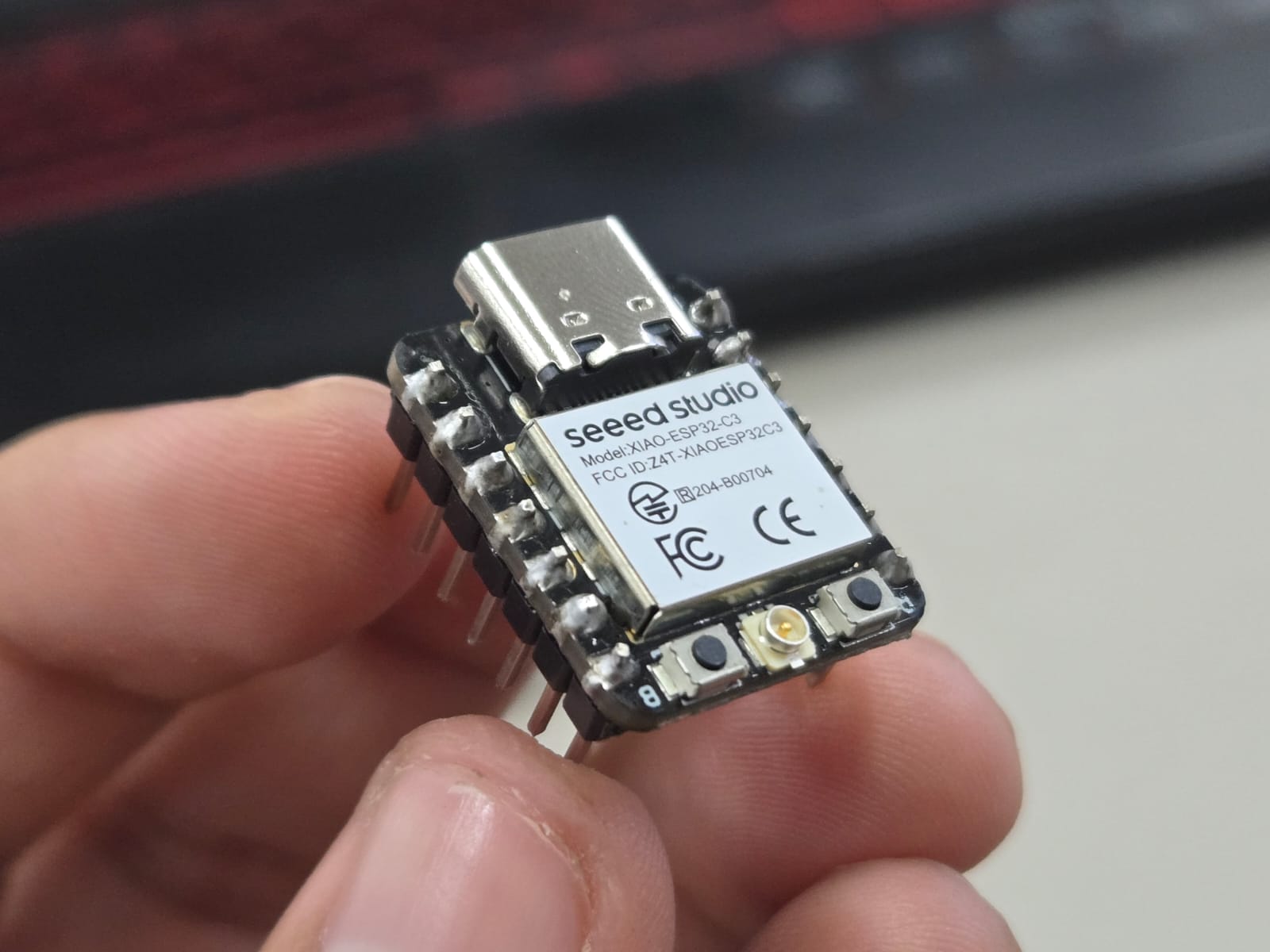
Individual Assignment — XIAO ESP32-C3
For my individual assignment, I worked with the Seeed Studio XIAO ESP32-C3. The objective was to explore its datasheet, understand its architecture, and program it to interact with local input/output devices and communicate through wired serial connection.
1) Local Context & Hardware Acquisition
According to the official Seeed Studio website , the XIAO ESP32-C3 is priced at approximately $4.90 USD.
However, in Peru, the availability of this microcontroller is limited. When available through local distributors, its price increases significantly to approximately 50 Peruvian soles - 15USD, which is nearly double its original retail value.
Due to limited stock and urgent availability, I had to purchase the Grove Vision AI V2 Kit, which includes:
- XIAO ESP32-C3
- OV5647 Camera Module
- Vision AI board integration
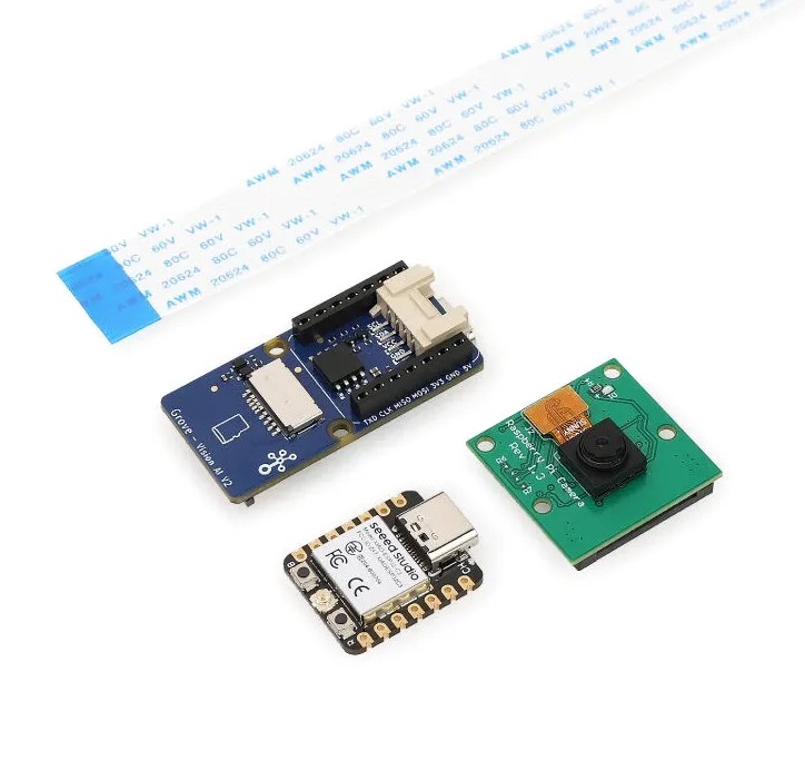
Grove Vision AI V2: kit with XIAO ESP32-C3 and OV5647 camera module.
While the camera module may not be directly used for this week’s assignment, acquiring this kit ensured immediate access to the ESP32-C3 board.
Access to microcontrollers in Peru is not always straightforward. Some of my classmates relied on borrowing boards or purchasing used ones from previous Fab Academy students. This highlights how geographic and logistical constraints influence technological experimentation.
2) Datasheet Exploration
The XIAO ESP32-C3 is based on the ESP32-C3 microcontroller, developed by Espressif Systems.
Official technical documentation: ESP32-C3 Datasheet (PDF)
2) Technical Overview from Datasheet
The XIAO ESP32-C3 is based on the ESP32-C3 SoC developed by Espressif Systems. Official documentation: ESP32-C3 Datasheet (PDF)
| Feature | Specification |
|---|---|
| Processor | 32-bit RISC-V single core |
| Clock Speed | Up to 160 MHz |
| SRAM | ~400 KB |
| Flash Memory | 4 MB external SPI |
| GPIO | Up to 15 programmable pins |
| Peripherals | UART, SPI, I2C, PWM, ADC (12-bit) |
| USB Connectivity | Native USB |
| Wireless | WiFi 2.4GHz + BLE 5.0 |
| Temperature Sensor | Integrated internal sensor |
| Manufacturing Process | 40nm technology |
| Package | QFN32 |
This table summarizes the main hardware capabilities extracted from the official datasheet.
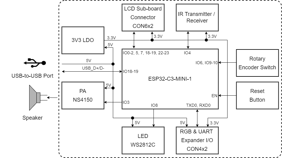
Block diagram extracted from the official datasheet. It shows the RISC-V CPU core, memory hierarchy, RF subsystem, peripheral interfaces, and SPI flash controller.
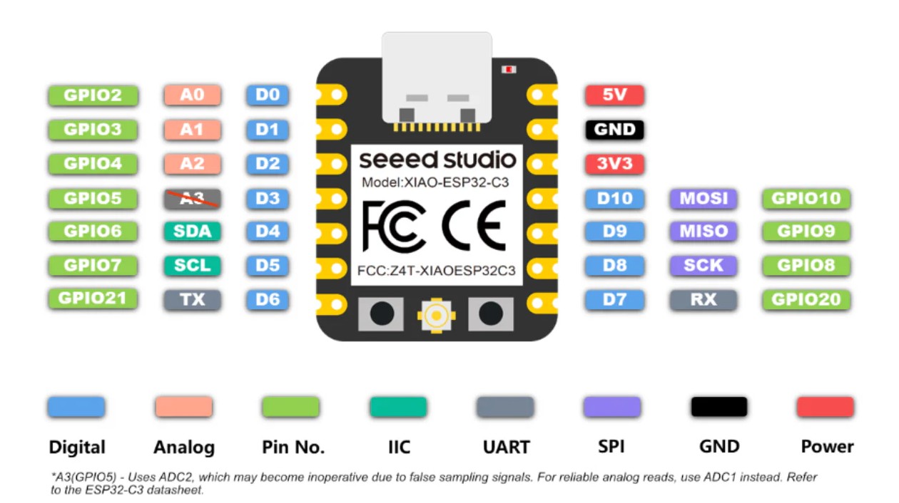
XIAO ESP32 C3 Pin out.
2) Architectural Overview
The ESP32-C3 is built on a single-core 32-bit RISC-V processor. Unlike AVR's modified Harvard architecture, it integrates instruction and data processing with a more advanced memory structure.
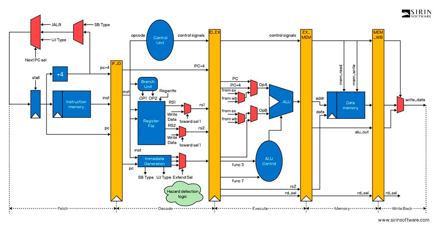
The RISC-V instruction set architecture (ISA) is open-source, modular, and scalable. This differs from proprietary AVR architectures. Learn more at RISC-V Specifications.
Integrated WiFi and BLE transform the microcontroller from a simple embedded controller into a network-enabled computational node.
3) Implementing Programming Protocols
Programming the ESP32-C3 involves transferring compiled binary data from the computer to the microcontroller’s Flash memory.
- Code written in C++ (Arduino framework)
- Compiled using riscv32-esp-elf-gcc
- Converted into a .bin binary file
- Flashed into SPI memory via USB
Unlike older AVR boards, the ESP32-C3 uses native USB communication and does not require an external FTDI programmer.
4) Development Environment Setup — XIAO ESP32-C3 (Windows + Arduino IDE)
Unlike the RP2040 core, the XIAO ESP32-C3 uses the ESP32 Arduino core. Therefore, the installation process requires specific board package configuration.
Step 1 — Install Arduino IDE
Download the latest version from: https://www.arduino.cc/en/software
- Download the Windows Installer (.exe)
- ✔ Enable “Install USB drivers” during installation
Step 2 — Add ESP32 Board Support (Mandatory)
1️⃣ Add Board Manager URL
Open Arduino IDE → File → Preferences
In Additional Boards Manager URLs, paste:
https://raw.githubusercontent.com/espressif/arduino-esp32/gh-pages/package_esp32_index.json
Click OK.
2️⃣ Install ESP32 Package
Go to: Tools → Board → Boards Manager
Search for:
esp32
Install: esp32 by Espressif Systems (Installation may take several minutes due to package size)
Step 3 — Select XIAO ESP32-C3
Connect the board via USB.
Go to:
- Tools → Board → ESP32 Arduino → XIAO_ESP32C3
- If not visible, select ESP32C3 Dev Module
- Tools → Port → COMx (new port that appears)
Hold the BOOT button → Connect USB → Release → Upload.
Step 4 — Test with Blink Example
Open:
File → Examples → Basics → Blink
On ESP32-C3 the built-in LED is usually:
#define LED_BUILTIN 8
If it does not blink, try pins 2 or 10 depending on board revision.
- ✔ Click Verify
- ✔ Click Upload
If the LED blinks → Environment setup successful.
Step 5 — Useful Libraries
Access via:
Sketch → Include Library → Manage Libraries
| Library | Purpose |
|---|---|
| WiFi | Network communication (built-in) |
| Bluetooth (BLE) | Low energy communication |
| Adafruit GFX | Display control |
| SSD1306 | OLED displays |
| FastLED | Advanced LED control |
| Servo | Motor control |
Official Resources
- Board Documentation: https://wiki.seeedstudio.com/XIAO_ESP32C3/
- ESP32 Arduino Core: https://github.com/espressif/arduino-esp32
- Arduino IDE: https://www.arduino.cc/en/software
⚡ Key Technical Notes about ESP32-C3
| Parameter | Important Detail |
|---|---|
| Logic Level | 3.3V (⚠ NOT 5V tolerant) |
| Wireless | Integrated WiFi + BLE |
| USB | Native USB (no FTDI required) |
| Interfaces | I2C, SPI, UART, PWM available on most GPIO |
| Performance | Significantly more powerful than 8-bit AVR |
Compared to simpler microcontrollers, the ESP32-C3 provides higher processing power, integrated wireless communication, and advanced peripheral control, making it suitable for IoT and distributed embedded systems.
5) Writing the LED Sequence Program
I programmed a timed LED sequence using three output pins:
void setup() {
  Serial.begin(115200);
  pinMode(D2, OUTPUT);
  pinMode(D3, OUTPUT);
  pinMode(D4, OUTPUT);

  Serial.println("");
  Serial.println("Hello, XIAO ESP32-C3!");
  Serial.println("Welcome to Wokwi :-)");
}

void loop() {
  Serial.println("Red");
  digitalWrite(D2, HIGH);
  delay(500);
  digitalWrite(D2, LOW);

  Serial.println("Green");
  digitalWrite(D3, HIGH);
  delay(500);
  digitalWrite(D3, LOW);

  Serial.println("Blue");
  digitalWrite(D4, HIGH);
  delay(500);
  digitalWrite(D4, LOW);
}
6) Circuit Simulation in Wokwi
Before assembling the physical circuit, I simulated the LED sequence using the online simulator: Wokwi
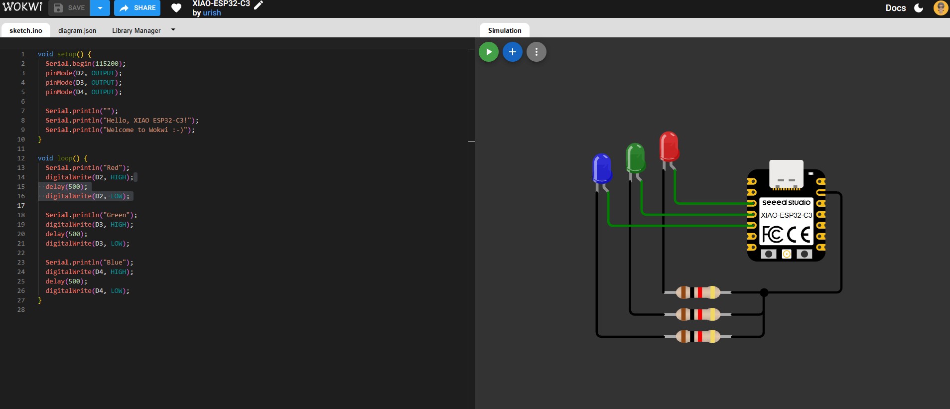
The simulation allowed verification of wiring and logic before assembling the physical prototype.
7) Physical Circuit Assembly
After simulation, the circuit was assembled on a breadboard using current-limiting resistors for each LED.
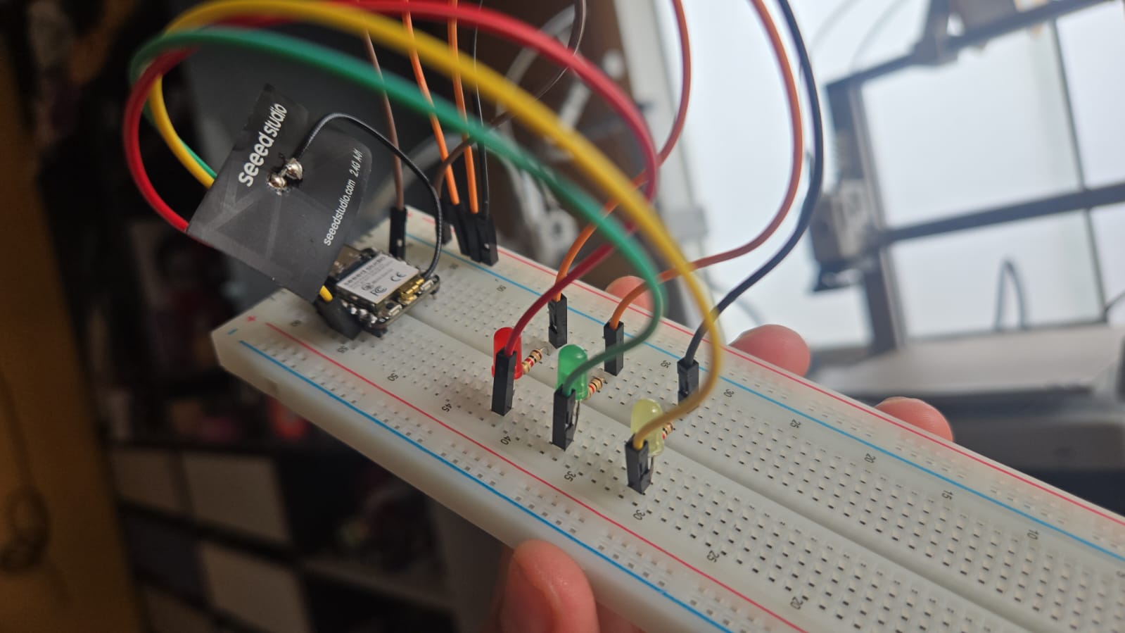
Final physical setup of the XIAO ESP32-C3 and LED sequence.
8) Reflection
Starting from zero knowledge in embedded programming, this process helped me understand how a microcontroller reads instructions from Flash memory and controls physical outputs.
Moving from simulation (Wokwi) to real hardware allowed me to understand the relationship between digital logic and physical circuitry.