
1. Tool Selection & Setup
For this assignment, the primary goal was to create a design that is fully parametric. This means that if the cardboard thickness varies (which it often does) or the laser cutter's kerf changes, I can update the entire design by changing a single number slider, rather than redrawing every joint manually.
Why Grasshopper (Rhino)?
I chose Rhino 8 with Grasshopper because it is the industry standard for algorithmic architecture. Unlike direct modeling (SketchUp, Blender), Grasshopper allows for "Visual Scripting," where geometry is defined by relationships and data flow.
| Software | Pros for Press-Fit Kits | Cons |
|---|---|---|
| Rhino + Grasshopper | Excellent 2D vector control, visual logic, real-time feedback. | Steep learning curve for nodes. |
| Fusion 360 | Great parameter table, precise constraints. | Can get heavy/slow with complex patterns. |
| Blender (Geometry Nodes) | Free, open-source, powerful. | Harder to export precise scale CAD files (DXF) without addons. |
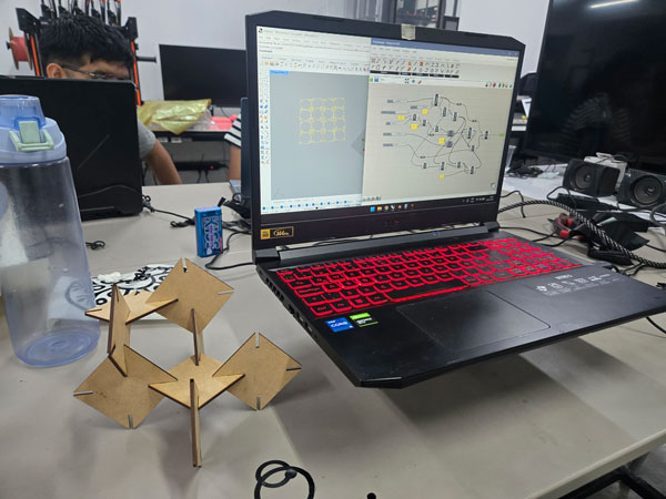
2. The Parametric Definition (Grasshopper)
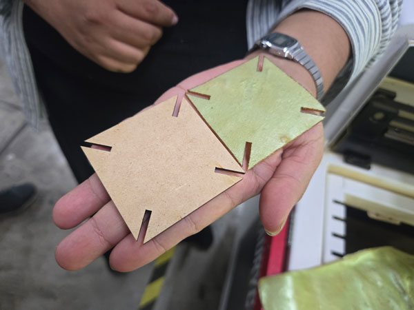
The core of my kit is a triangular module. The logic is divided into 6 distinct phases to ensure the slots always point towards the center and the dimensions are accurate for laser cutting.
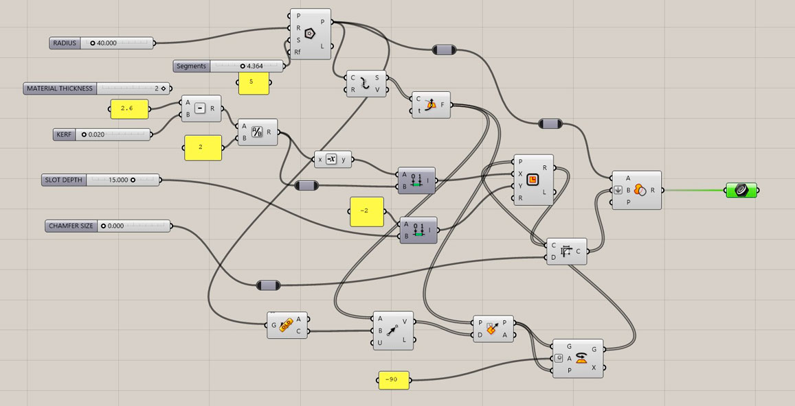
Fig 1. The complete Grasshopper definition overview.
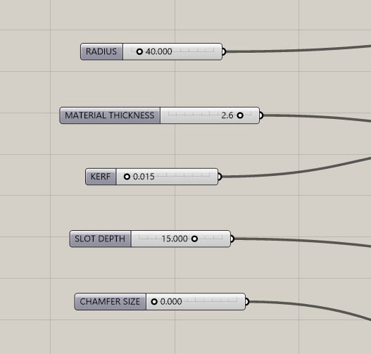
Phase 1: Global Parameters (Inputs)
These are the "knobs" that control the design. I set up Number Sliders for the following variables:
Radius: Controls the circumscribed radius of the triangle.Material Thickness: Measured with a caliper (e.g., 3.0mm).Kerf: The laser beam width (approx 0.15mm). Crucial for tight fit.Slot Depth: How deep the connection goes.Chamfer Size: To clip the sharp corners of the triangle.
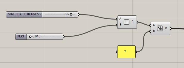
Phase 2: The Math (Kerf Calculation)
Before drawing geometry, I calculated the Actual Slot Width. The laser burns away material, so the hole in the design must be smaller than the material thickness.
Actual Width = Material Thickness - Kerf
I then divided this by 2 to find the distance from the center line to the edge of the cut.
Phase 3: Base Geometry
Component Logic:
Input: Radius Slider → Polygon (Segments = 3).
Process: This generates the base triangle.
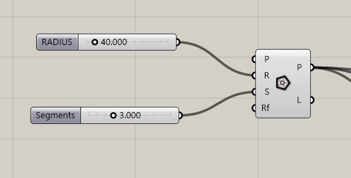
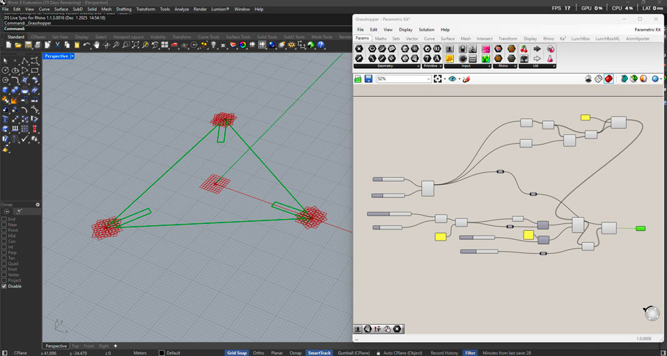
Fig 2. Generating the base shape.
Phase 4: Slot Orientation (The Challenge)
The most difficult part was ensuring the rectangular slots always pointed toward the geometric center of the triangle. If I used standard frames, the slots pointed outwards or sideways.
The Solution:
- Explode the polygon to get the 3 sides.
- Use Horizontal Frame at parameter
0.5to get a plane in the middle of each side. - Use Area to find the
Centroidof the triangle. - Create a Vector 2Pt from the Frame Origin to the Centroid.
- Use Align Plane to force the Frame's Y-axis to align with that vector.
- Finally, Rotate the plane 90 degrees so the slot cuts perpendicular to the edge.
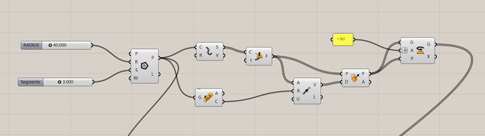
Fig 3. Vector logic to align planes towards the centroid.
Phase 5: Creating the Cutters & Boolean
Once the planes were oriented correctly, I used the Rectangle component. I used Construct Domain to center the rectangle on the plane (Width/2 to -Width/2).
Finally, I used Region Difference:
- Input A: The Chamfered Triangle.
- Input B: The 3 Rectangular Cutters (Flattened).
The result is a clean, parametric closed curve ready for baking.
3. Computational Design via Python (Blender)
To deepen my understanding of the "Systems" thinking behind the geometry, I ported the logic from Visual Scripting (Grasshopper) to Code (Python within Blender). This allows for greater recursion and automation capabilities.
The AI-Assisted Workflow
I utilized GEMINI IA to assist in writing the bpy (Blender Python) script. My prompt strategy was to describe the geometric constraints clearly:
"Generate a Python script for Blender that creates a parametric triangle with press-fit slots. It must have variables for Radius, Thickness, and Kerf. The slots must calculate their position based on polar coordinates (30, 150, 270 degrees) to ensure they always point to the center."
The Code Logic
The final script decouples the rotation of the triangle from the position of the slots, allowing for interesting variations. Here is the snippet used to generate the slots:
# Python Snippet for Oriented Slots
for i in range(3):
    # Calculate Angle (30, 150, 270) + Orbit Parameter
    orbit_angle_deg = base_angles[i] + PARAM_SLOTS_ORBIT
    orbit_rad = math.radians(orbit_angle_deg)

    # Polar Coordinates
    pos_x = distance_to_edge * math.cos(orbit_rad)
    pos_y = distance_to_edge * math.sin(orbit_rad)

    # Orientation Logic (Pointing to Center)
    # We rotate the cutter 90 degrees relative to its position angle
    axis_rot_rad = math.radians(orbit_angle_deg + 90 + PARAM_SLOTS_AXIS)

    cutter_obj.rotation_euler = (0, 0, axis_rot_rad)
Blender Code
import bpy
import bmesh
import math
from mathutils import Vector, Euler

# ==========================================
# 1. CONTROL PARAMETERS
# ==========================================
PARAM_RADIUS = 1.5
PARAM_THICKNESS = 0.05
PARAM_KERF = 0.002
PARAM_SLOT_DEPTH = 0.3
PARAM_CHAMFER = 0.2

# --- ROTATION CONTROLS ---
PARAM_TRI_ROTATION = 90.0    # Giro del Triángulo
PARAM_SLOTS_ORBIT = 0.0      # Giro de posición de muescas
PARAM_SLOTS_AXIS = 0.0       # Giro individual de corte

ACTUAL_SLOT_WIDTH = PARAM_THICKNESS - PARAM_KERF

# ==========================================
# 2. SCENE CLEANUP
# ==========================================
def clean_scene():
    if bpy.context.object and bpy.context.object.mode != 'OBJECT':
        bpy.ops.object.mode_set(mode='OBJECT')

    # Borrar objetos
    for o in bpy.data.objects:
        if o.name.startswith("FabModule") or o.name.startswith("Cutter"):
            bpy.data.objects.remove(o, do_unlink=True)

    # Borrar mallas
    for m in bpy.data.meshes:
        if m.name.startswith("FabModule") or m.name.startswith("Cutter"):
            bpy.data.meshes.remove(m)

clean_scene()

# ==========================================
# 3. GENERATE TRIANGLE
# ==========================================
mesh = bpy.data.meshes.new("FabModule_Mesh")
obj = bpy.data.objects.new("FabModule_Tri", mesh)
bpy.context.collection.objects.link(obj)
bpy.context.view_layer.objects.active = obj
obj.select_set(True)

bm = bmesh.new()

# Base rotation + parameter
tri_rot_rads = math.radians(90 + PARAM_TRI_ROTATION)

bmesh.ops.create_circle(
    bm,
    cap_ends=True,
    radius=PARAM_RADIUS,
    segments=3,
    matrix=Euler((0, 0, tri_rot_rads)).to_matrix()
)
bm.to_mesh(mesh)
bm.free()

# ==========================================
# 4. APPLY CHAMFER
# ==========================================
bpy.ops.object.mode_set(mode='EDIT')
bpy.ops.mesh.select_all(action='SELECT')
bpy.ops.mesh.bevel(
    offset=PARAM_CHAMFER,
    offset_type='OFFSET',
    segments=1,
    affect='VERTICES'
)
bpy.ops.object.mode_set(mode='OBJECT')

# ==========================================
# 5. GENERATE NOTCHES
# ==========================================

distance_to_edge = PARAM_RADIUS * math.cos(math.radians(60))

cutters = []
base_angles = [30, 150, 270]

for i in range(3):
    orbit_angle_deg = base_angles[i] + PARAM_SLOTS_ORBIT
    orbit_rad = math.radians(orbit_angle_deg)

    pos_x = distance_to_edge * math.cos(orbit_rad)
    pos_y = distance_to_edge * math.sin(orbit_rad)

    cutter_mesh = bpy.data.meshes.new(f"Cutter_Mesh_{i}")
    cutter_obj = bpy.data.objects.new(f"Cutter_Obj_{i}", cutter_mesh)
    bpy.context.collection.objects.link(cutter_obj)

    bm_cutter = bmesh.new()
    bmesh.ops.create_cube(bm_cutter, size=1.0)
    bm_cutter.to_mesh(cutter_mesh)
    bm_cutter.free()

    cutter_obj.scale = (ACTUAL_SLOT_WIDTH, PARAM_SLOT_DEPTH * 2, 1.0)
    cutter_obj.location = (pos_x, pos_y, 0)

    # Rotación del corte
    axis_rot_rad = math.radians(orbit_angle_deg + 90 + PARAM_SLOTS_AXIS)
    cutter_obj.rotation_euler = (0, 0, axis_rot_rad)

    cutters.append(cutter_obj)

# ==========================================
# 6. BOOLEAN OPERATION
# ==========================================
bpy.context.view_layer.objects.active = obj
for cutter in cutters:
    mod = obj.modifiers.new(name="SlotCut", type='BOOLEAN')
    mod.object = cutter
    mod.operation = 'DIFFERENCE'
    mod.solver = 'FAST'

    cutter.display_type = 'WIRE'
    cutter.hide_render = True

print(f"¡Script ejecutado correctamente! Triángulo en {PARAM_TRI_ROTATION}°")
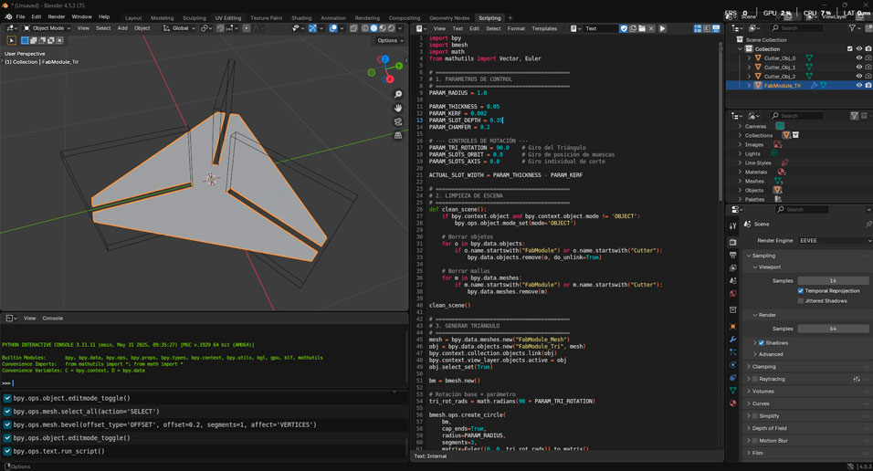
Fig 4. The Python script in Blender.
4.Laser Cutting Process – From Parametric Model to Physical Object
Once the parametric construction kit was fully defined in Grasshopper and later translated into Python for Blender, the next step was materialization. The digital geometry was exported as SVG files, preserving scale and line hierarchy, and prepared for fabrication using RDWorks, the software compatible with the laser cutter controller.
This stage represents a critical transition: the moment where parametric logic becomes material reality. As in architecture, drawings are not the final goal — they are instructions for fabrication.

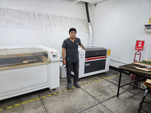
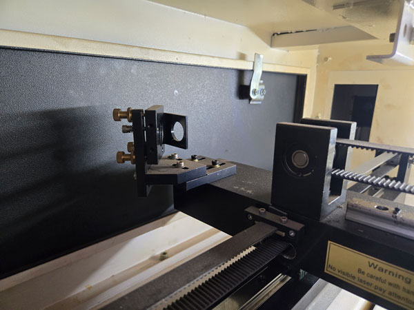
Laser Cutter Specifications
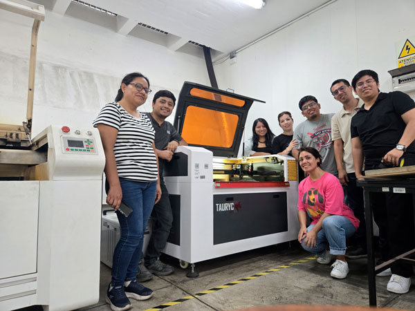
The fabrication was carried out using a Tauryc 9060 CO₂ Laser Cutter, a 100W machine equipped with a RUIDA 6445G controller. Understanding the machine’s technical parameters was fundamental to correctly calibrating speed, power, and kerf compensation.
| Specification | Detail |
|---|---|
| Model | Tauryc 9060 |
| Laser Type | CO₂ |
| Power | 100W |
| Working Area | 60 x 90 cm |
| Controller | RUIDA 6445G |
| Manufacturing Origin | China |
The working area dimensions directly influenced nesting decisions, material layout, and duplication strategy for the kit pieces.
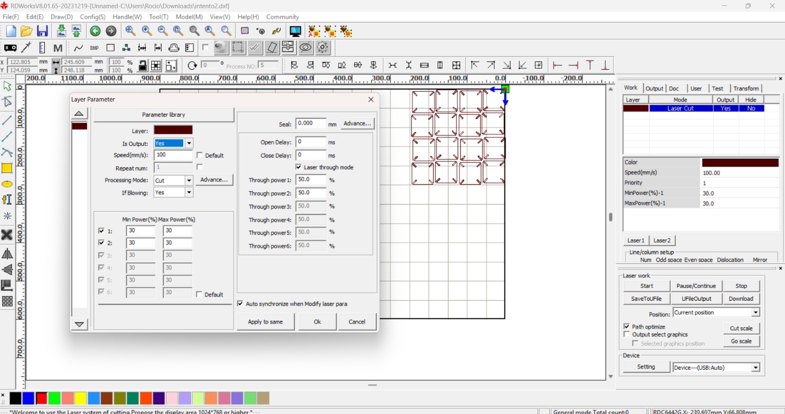
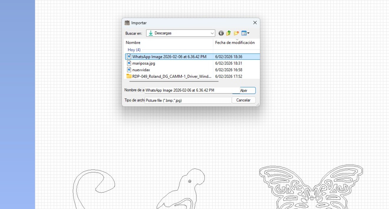
File Preparation in RDWorks
The exported SVG files from Grasshopper and Blender were imported into RDWorks. During this process, it was essential to verify:
- Correct scale preservation (1:1 ratio)
- Line type recognition (vector cut vs non-output lines)
- Positioning within the 60x90 cm working bed
- Material optimization and duplication strategy
The geometry was assigned to a vector cutting layer with output enabled. Care was taken to avoid duplicated lines, as overlapping vectors can result in double cuts and excessive material burning.
Power, Speed and Kerf Considerations
The calibration process was directly informed by the group kerf tests conducted earlier in the week. Since the parametric kit relied on press-fit logic, kerf compensation was not optional — it was structural.
Parameters were adjusted based on material thickness and behavior. Excessive power increases burning and widens the kerf; insufficient power leads to incomplete cuts and weak edges.
The final configuration balanced:
- Cutting speed relative to material density
- Laser power stability (minimum/maximum)
- Air assist activation
- Single-pass cutting to avoid overheating
From an architectural standpoint, this phase resembles material prototyping. Just as structural joints require tolerance calculations, laser joints require kerf logic.
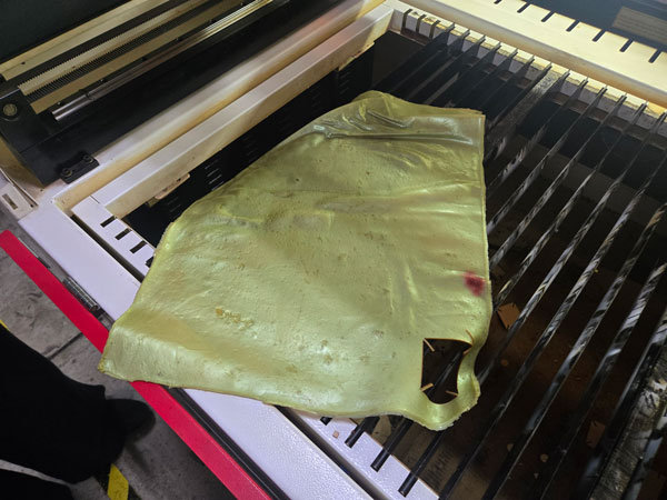
Material Exploration – Wood and Bioplastics
The initial fabrication tests were performed on rigid sheet material to validate joint precision and assembly stability. Once validated, experimentation expanded into laser-cut bioplastics produced during REGEN workshops.
Unlike rigid boards, bioplastics introduce flexibility and non-planar potential. This allowed exploration of curved geometries, foldable elements, and hybrid structural behavior.
Working with bioplastic sheets challenged the traditional “flat-pack” logic of laser cutting and opened possibilities for soft structures, wearable components, and adaptable assemblies.
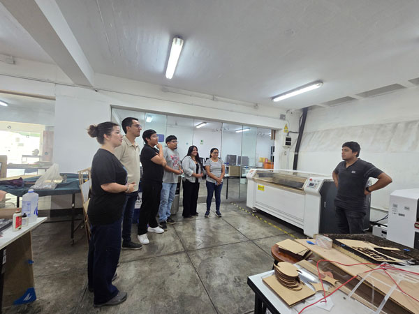
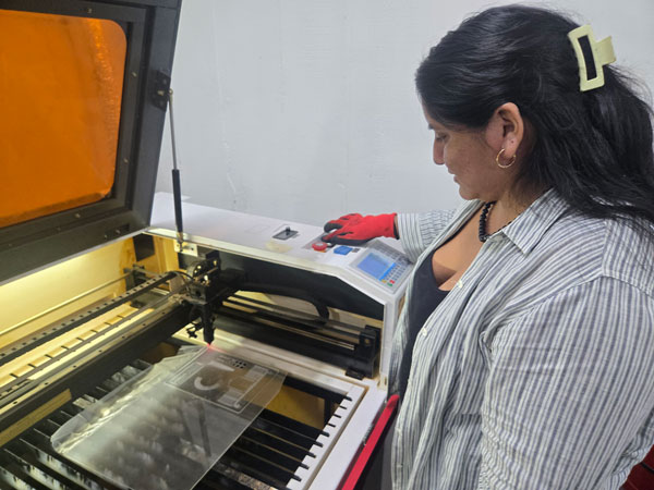
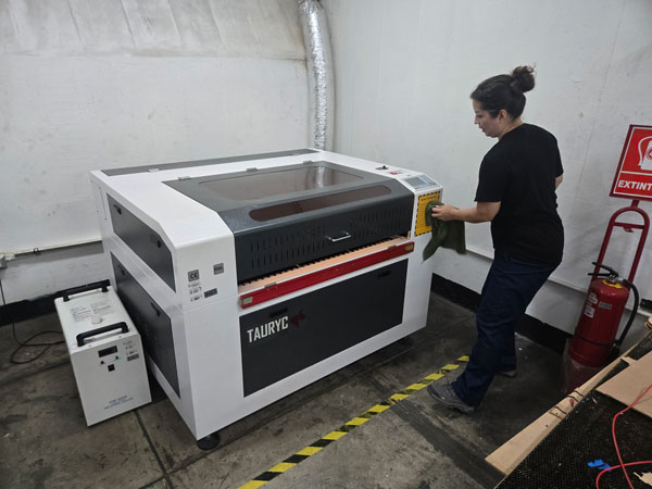
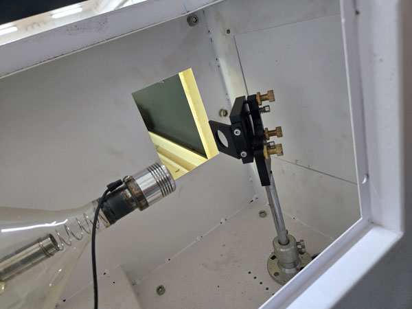
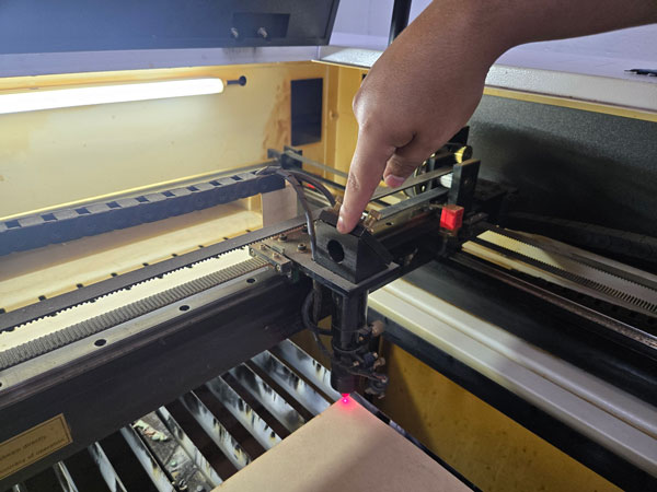
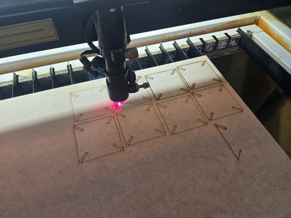
Machine Setup and Execution
After transferring the prepared file to the machine via USB, the job was loaded through the RUIDA control panel. A framing test was performed to confirm spatial boundaries and alignment with the material sheet.
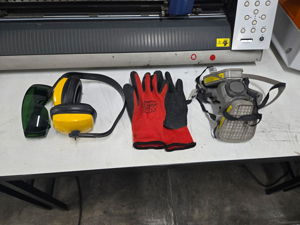
The material was secured on the bed, focus height verified, and air extraction confirmed before initiating the cut.
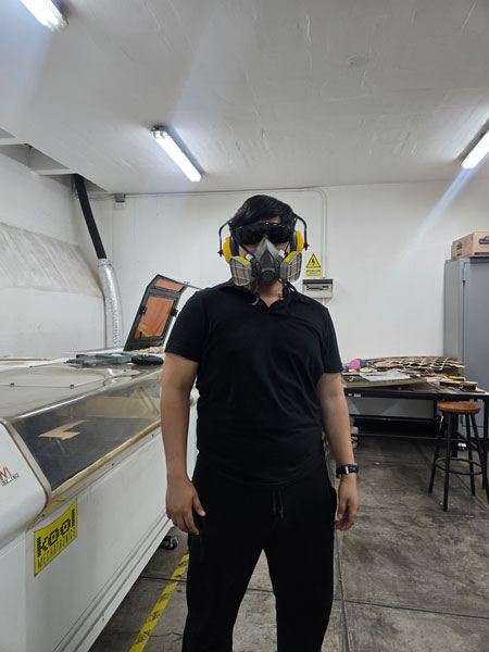
During operation, constant supervision was maintained. Laser cutting must never be left unattended, particularly when working with organic or experimental materials.
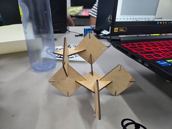
Assembly and Functional Application
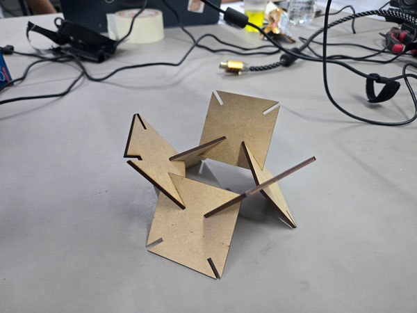
Once cut, the parametric pieces were assembled into two primary configurations:
- Phone stand
- Laptop elevation support for ventilation improvement
The press-fit logic proved effective, validating the kerf-adjusted slot design. The system demonstrated modular adaptability, where identical components generate different functional typologies.
From an architectural lens, this echoes modular construction strategies — repetition, system logic, and adaptability through controlled variation.
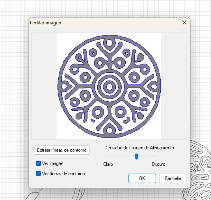
5.Vinyl Cutting Process – Graphic Fabrication and Precision
In parallel with the parametric construction kit, the second individual task consisted of producing a vinyl cut using the Roland GX-24 Vinyl Cutter. Unlike laser cutting, which removes material through thermal ablation, vinyl cutting operates through controlled blade pressure, requiring a different type of calibration and sensitivity.
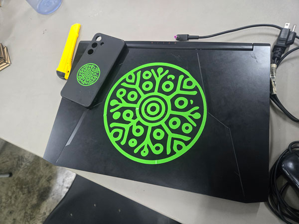
For this exercise, I produced the REGEN project logo in two different scales: one version sized for my laptop and a smaller version adapted for my phone case. This dual-scale application allowed me to evaluate proportion, line thickness, and material behavior at different resolutions.
Machine Specifications – Roland GX-24
The vinyl cutting process was carried out using a Roland GX-24, a precision cutting plotter widely used for graphic fabrication, signage, and prototyping applications.
| Specification | Detail |
|---|---|
| Model | Roland GX-24 |
| Cutting Method | Mechanical blade cutting |
| Material | Adhesive vinyl |
| Blade Force Used | 80 gf |
The most critical parameter during this process was the blade force. After several test cuts, the blade force was calibrated to 80, allowing the vinyl layer to be cut precisely without penetrating the backing paper.
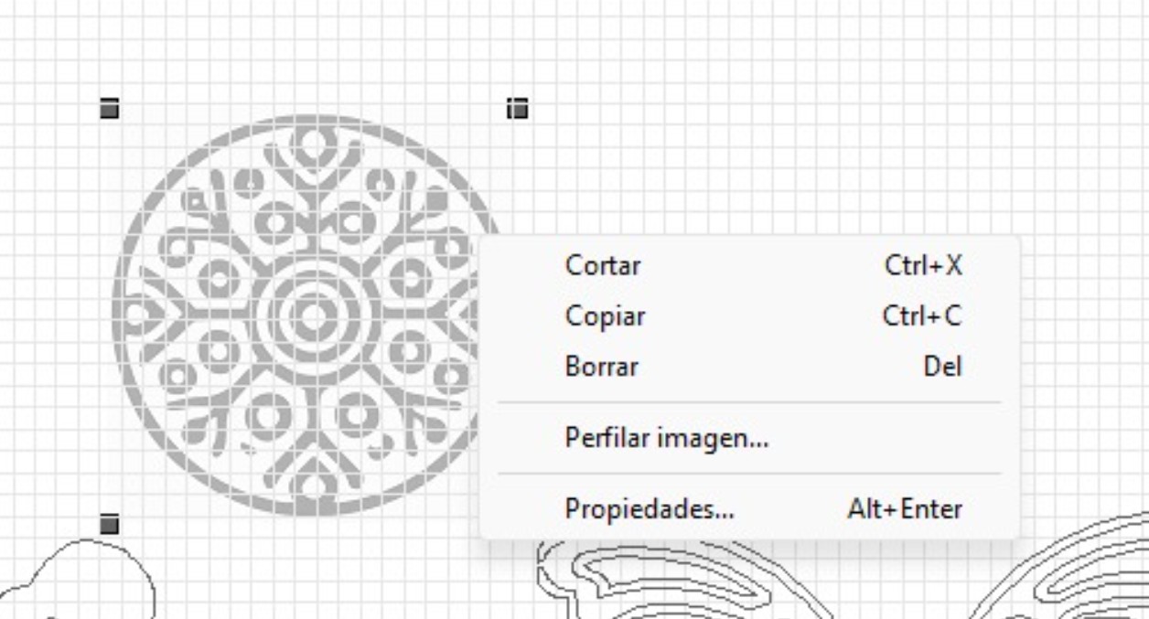
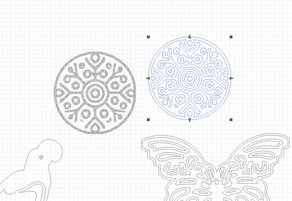
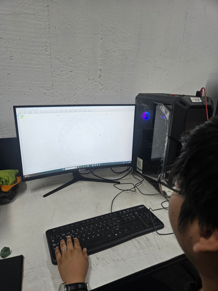
File Preparation and Vector Logic
The REGEN logo was prepared as a vector file, ensuring that all lines were converted into clean paths. Unlike raster images, vinyl cutting requires continuous vector geometry so that the blade follows a defined trajectory.
Special attention was given to:
- Closed vector paths
- Line thickness adaptation for small-scale cutting
- Spacing between internal elements to avoid tearing during weeding
- Maintaining proportional consistency across both sizes
In architectural terms, this process resembles façade detailing at different scales. A detail that works at 1:50 may fail at 1:5. Similarly, the logo required adjustments to remain legible and structurally coherent when reduced.
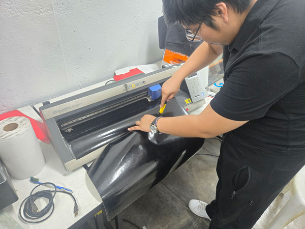
Cutting Execution and Calibration
Once the vinyl sheet was loaded into the Roland GX-24, alignment was verified through a test feed. The machine origin was set manually to ensure efficient material usage.
Before executing the final cut, a small test square was performed to confirm that the blade force setting of 80 produced a clean separation of the vinyl layer without cutting through the backing.
After validation, the full logo was cut in both sizes. The machine operated smoothly, and the precision of the blade maintained sharp internal angles and smooth curves.
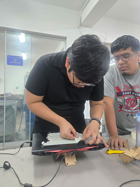
Weeding and Surface Application
After cutting, the excess vinyl was carefully removed in a process known as weeding. This stage requires patience and precision, especially when working with smaller typographic elements.
Transfer tape was then applied to lift the design as a single composition. The larger version was placed on my laptop, while the smaller version was adapted to the back of my phone case.
This dual application demonstrated how digital fabrication tools can extend beyond prototyping into identity, branding, and material personalization.
5.Learning Reflection – Vinyl as Architectural Communication
While vinyl cutting may appear simpler than laser fabrication, it reveals another dimension of digital production: graphic precision and material communication.
In architecture, visual language is inseparable from spatial language. Signage systems, wayfinding strategies, façade graphics, and identity layers all rely on the same vector logic used in vinyl cutting.
Understanding blade calibration, vector continuity, and scale sensitivity reinforces the importance of precision across disciplines. Just as a miscalculated kerf can weaken a joint, incorrect blade force can destroy fine details.
This exercise expanded my understanding of fabrication not only as structural production, but as graphic and communicative production.
Final Result
4. Architectural Thinking & Systems
This assignment goes beyond cutting cardboard; it is an exercise in System Design.
Press-Fit as Metabolism
The parametric kit resembles the architectural movement of Metabolism. The triangular unit is not a final product but a "cell." By defining the rules of connection (the slot depth and friction), the system allows for infinite growth.
Parameters as Constraints
In architectural terms, the Kerf is not just a machine tolerance; it is the "construction detail" that dictates the structural integrity of the whole assembly. By making it parametric, I am designing a system that is material-agnostic—it can work with cardboard, plywood, or acrylic by simply changing one variable.