WEEK 15 INTERFACE AND APPLICATION PROGAMMING
INTRODUCTION
This week's assignment is divided into two distinct parts:
- Group Assignment: The objective was to explore different methods of interconnecting devices and utilizing remote control platforms to establish communication between systems.
- Individual Assignment: For this part, I focused on reusing my Xiao RP2040 PCB to acquire sensor data. The goal was to stream this data to a computer and develop a Processing (Programming) script to visualize the information through a custom graphical user interface (GUI).
SCHEDULE
Due to the overlap with the Molding and Casting assignment, which I documented during the Friday holiday, I concentrated the workload for this week on Saturday and Sunday.
- Saturday: On Saturday morning, I focused on setting up the Programming environment and developing the initial code in collaboration with Gemini.
- During the afternoon, I explored various interface options, such as MIT App Inventor, but ultimately chose Blynk. I made this decision because I found less existing documentation for Blynk within the Fab Academy archive compared to other platforms, and I wanted to explore a different solution.
- Sunday: On Sunday morning, I worked on troubleshooting a persistent issue with the Blynk button interface, though I was unable to reach a definitive solution at that time.
- Consequently, I spent the afternoon finalizing the documentation to have it ready for the Monday review, leaving only minor refinements to be completed during the week.
GROUP ASSIGNMENT Remote Control and Cloud Platforms
FabLab Leon work groupBLYNK
Interconnecting different devices and controllers was a topic I previously explored during the Networking and Communications assignment:
Therefore, on this occasion, I focused on utilizing an online platform to remotely control a local device.
After evaluating several platforms, I chose Blynk. This platform allows me to create a custom mobile interface and interconnect it via the cloud to local hardware, in this case, an ESP32 Wrover connected to a temperature probe.
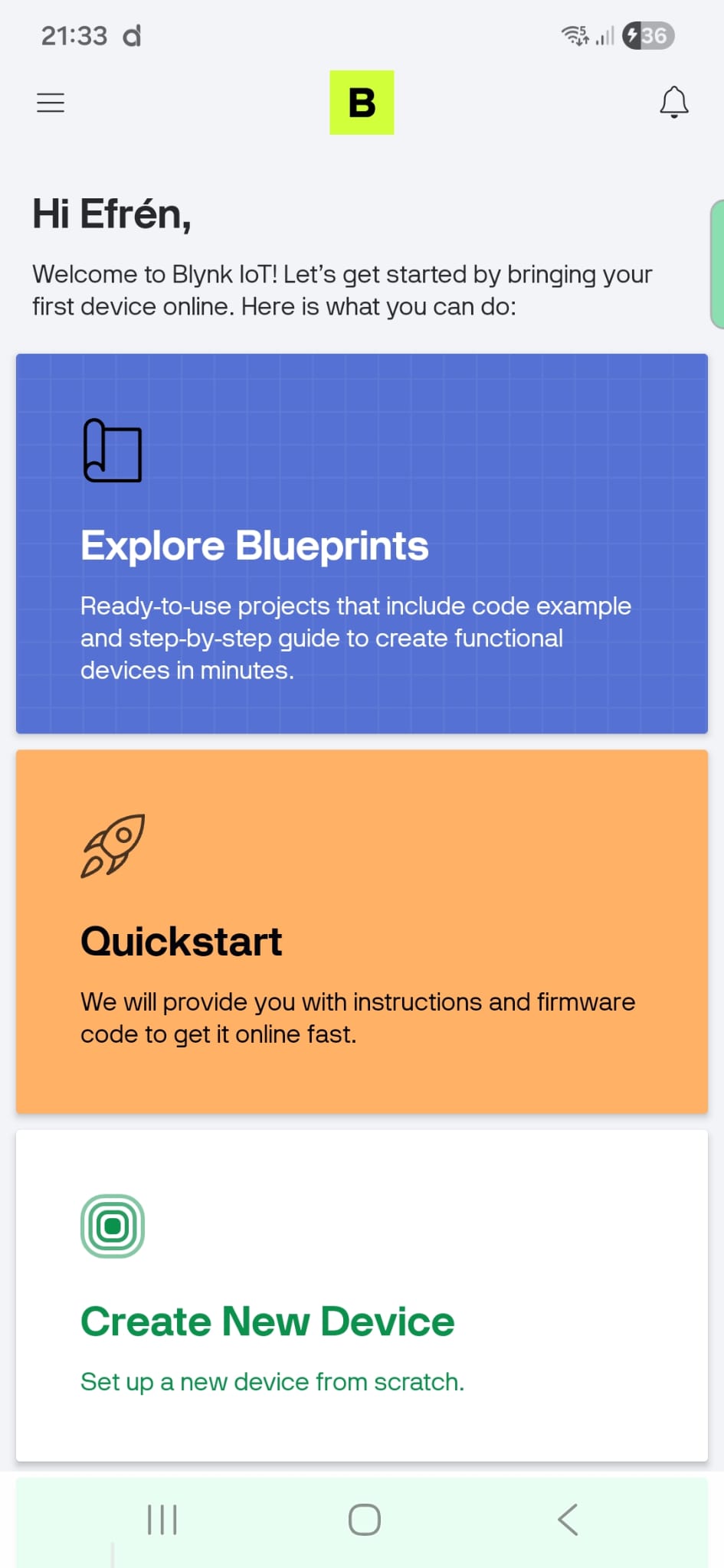
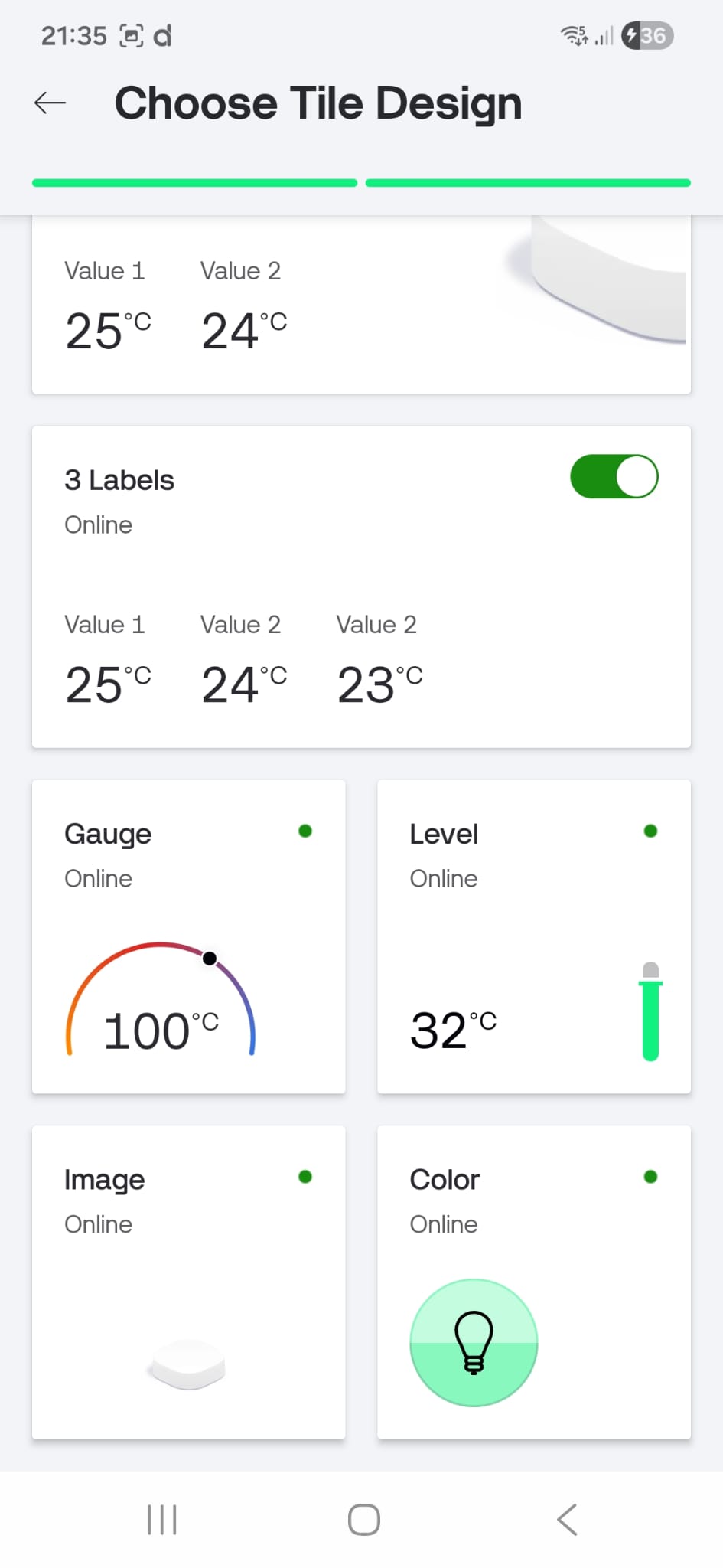
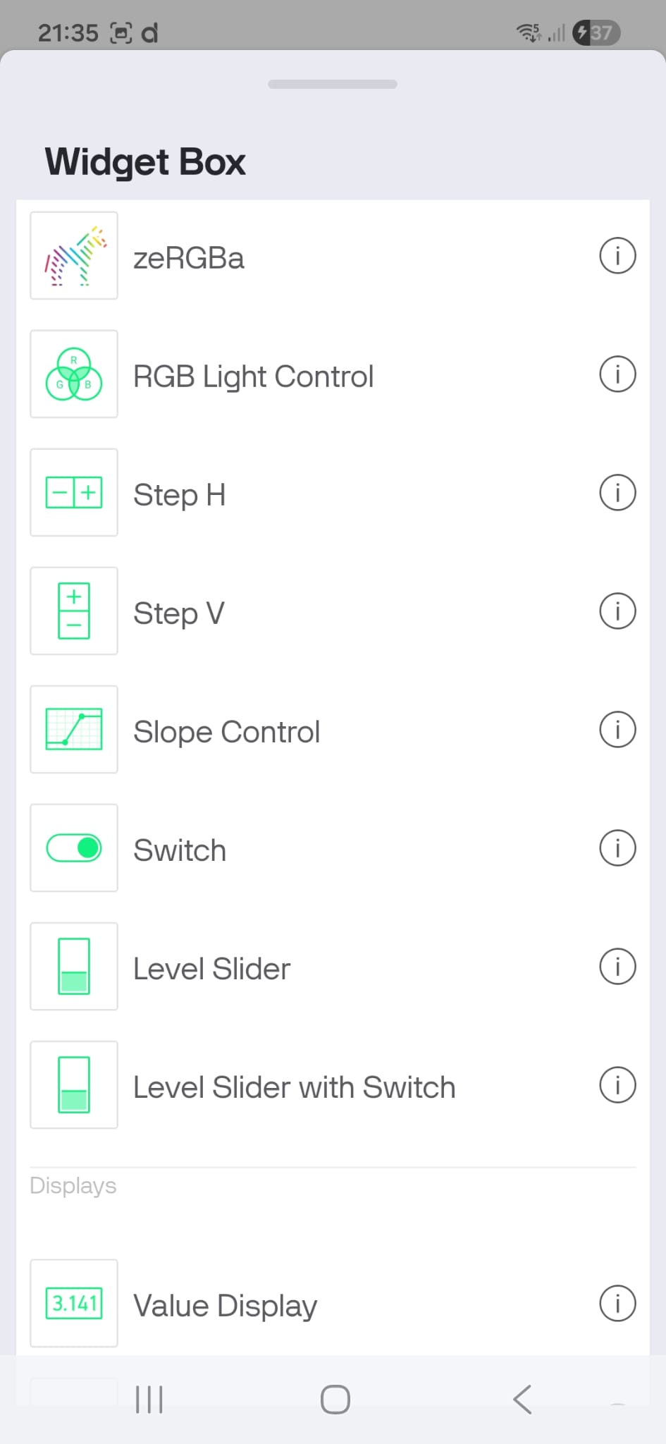
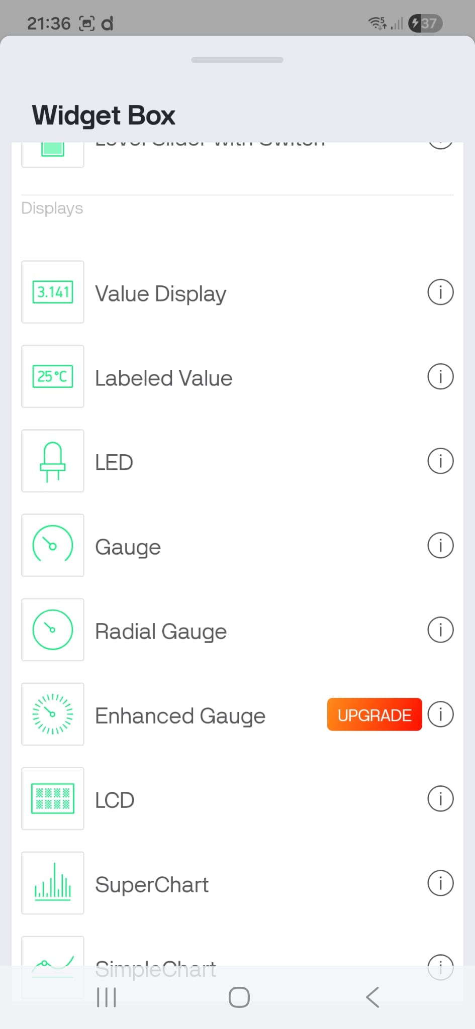
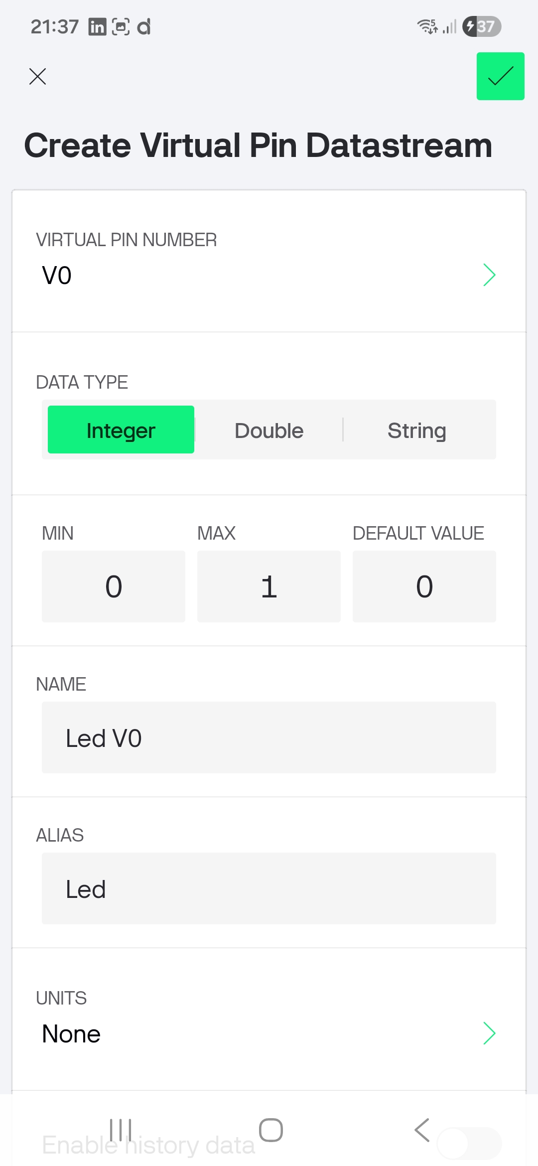
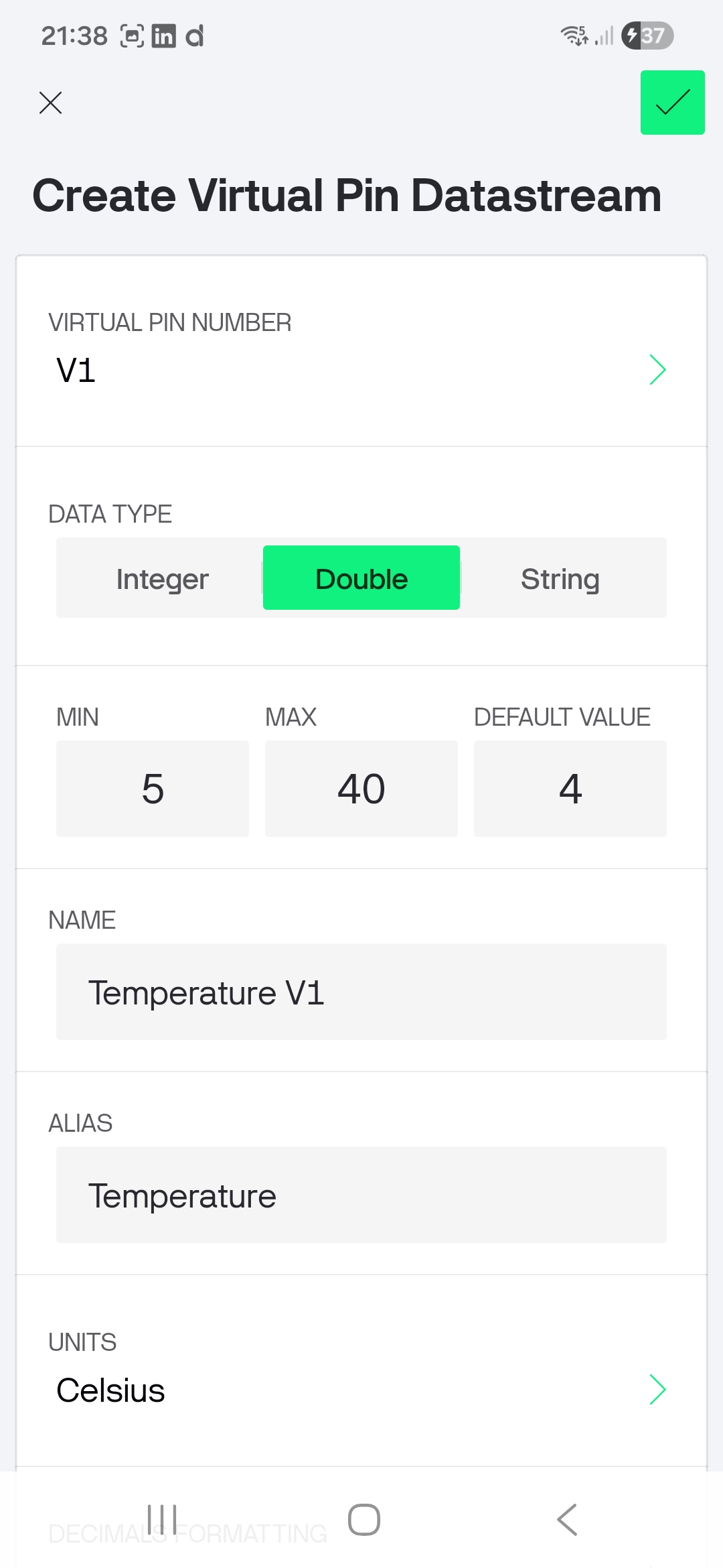
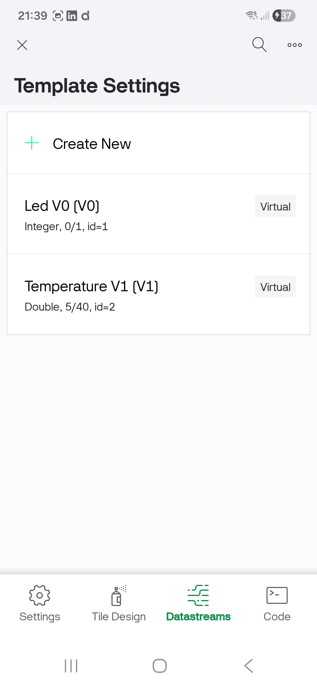
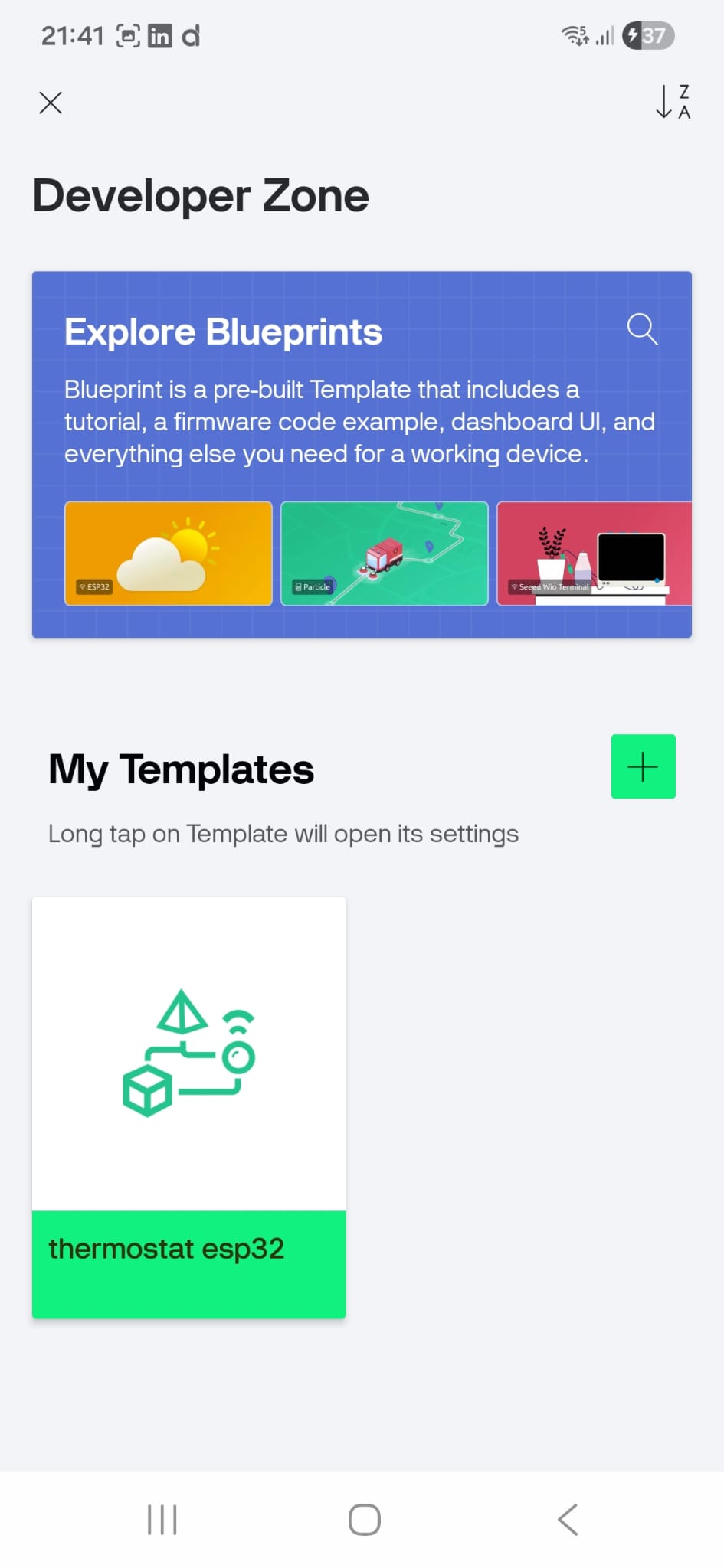
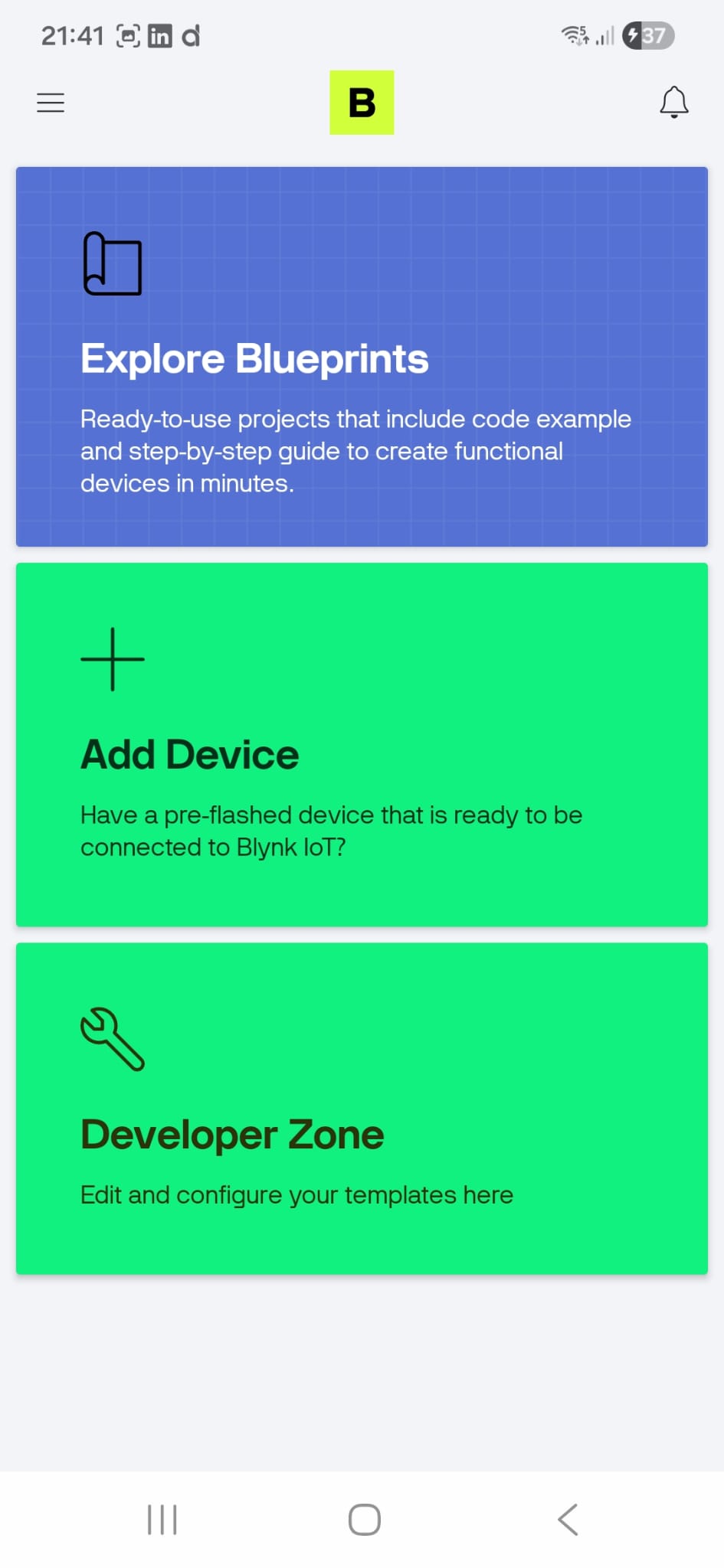
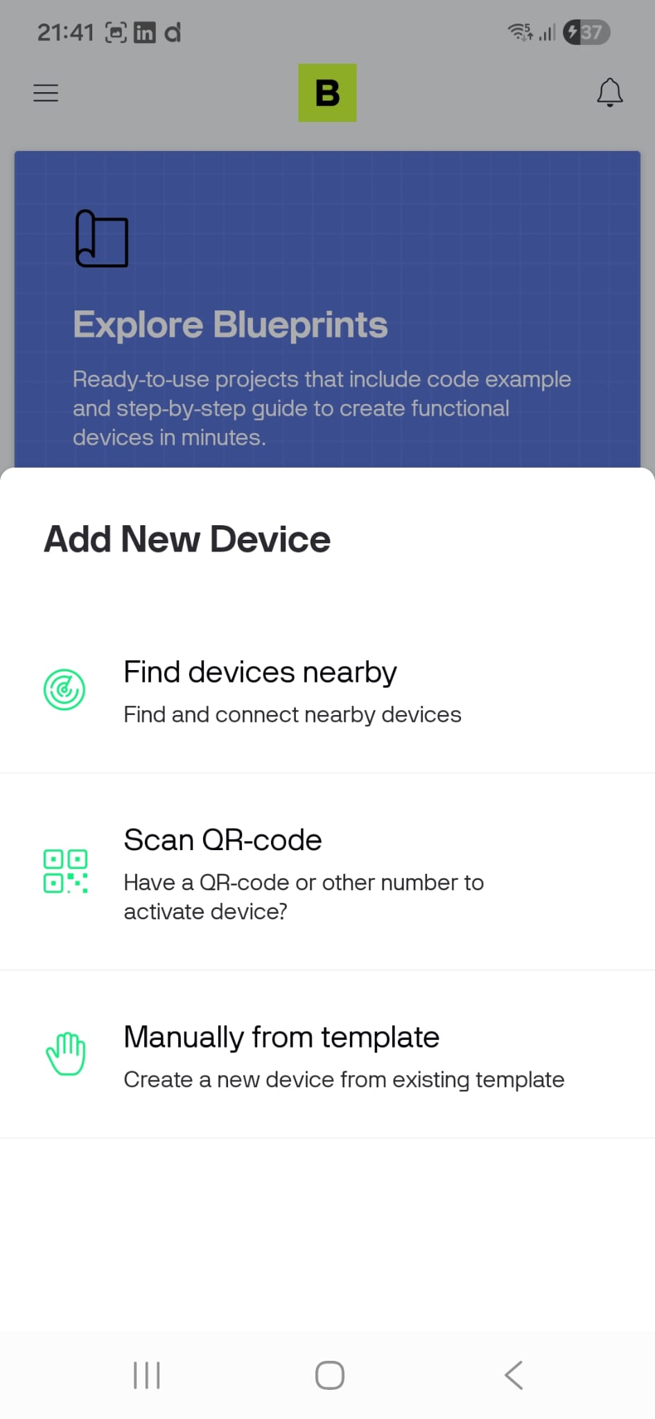
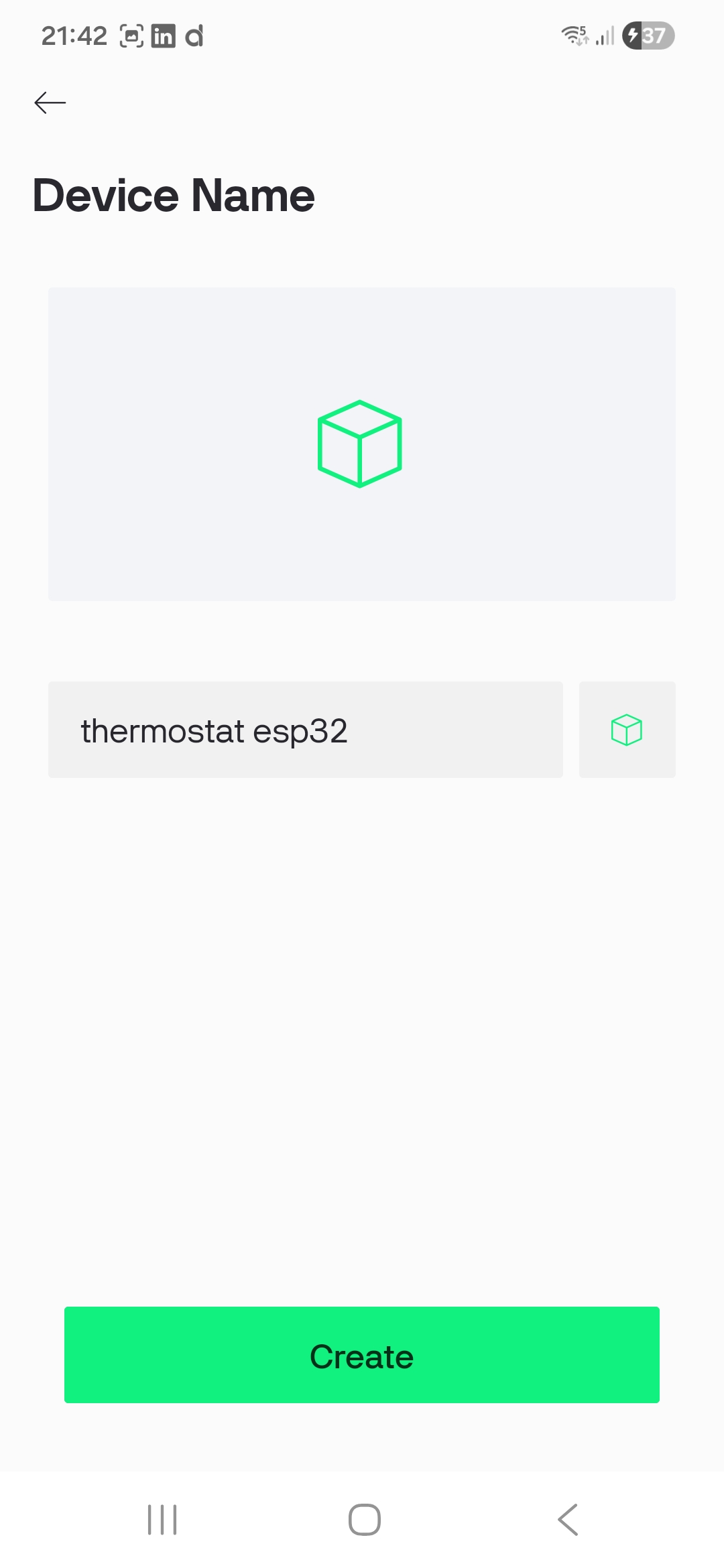
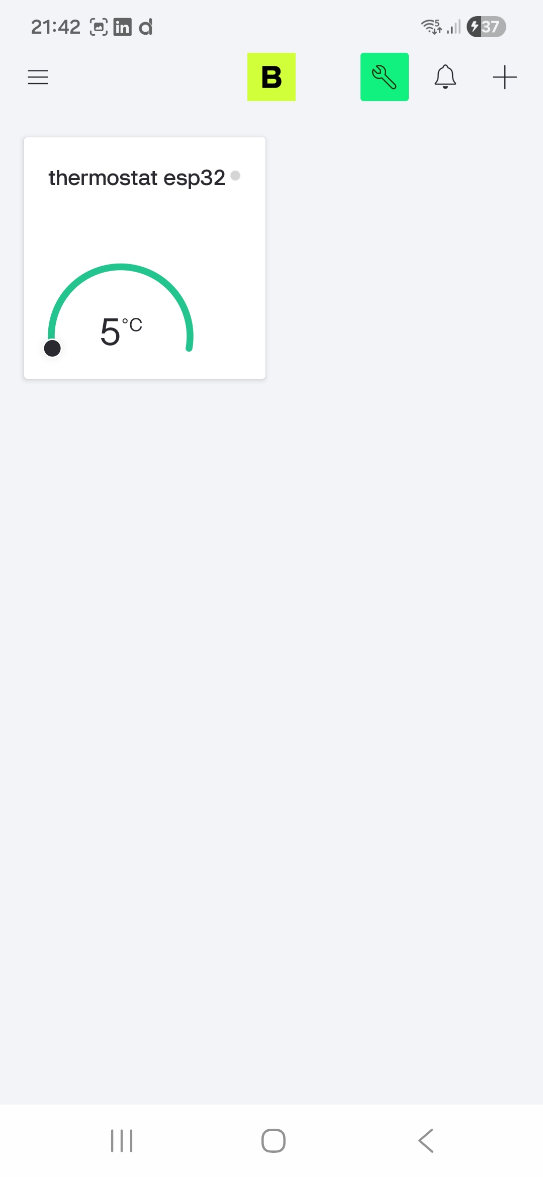
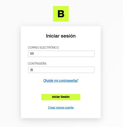
The first step involved downloading the Blynk app from the Play Store, creating an account, and designing a Template. Since the goal is to use a temperature probe, I designed a dashboard featuring:
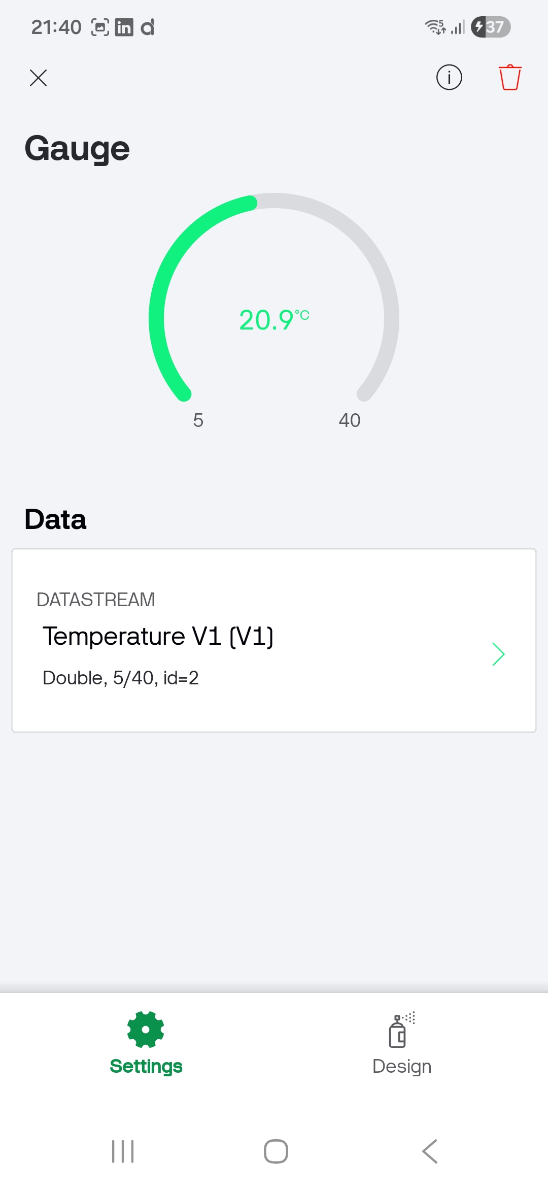
- A Gauge: To display the real-time temperature readings from the ESP32.
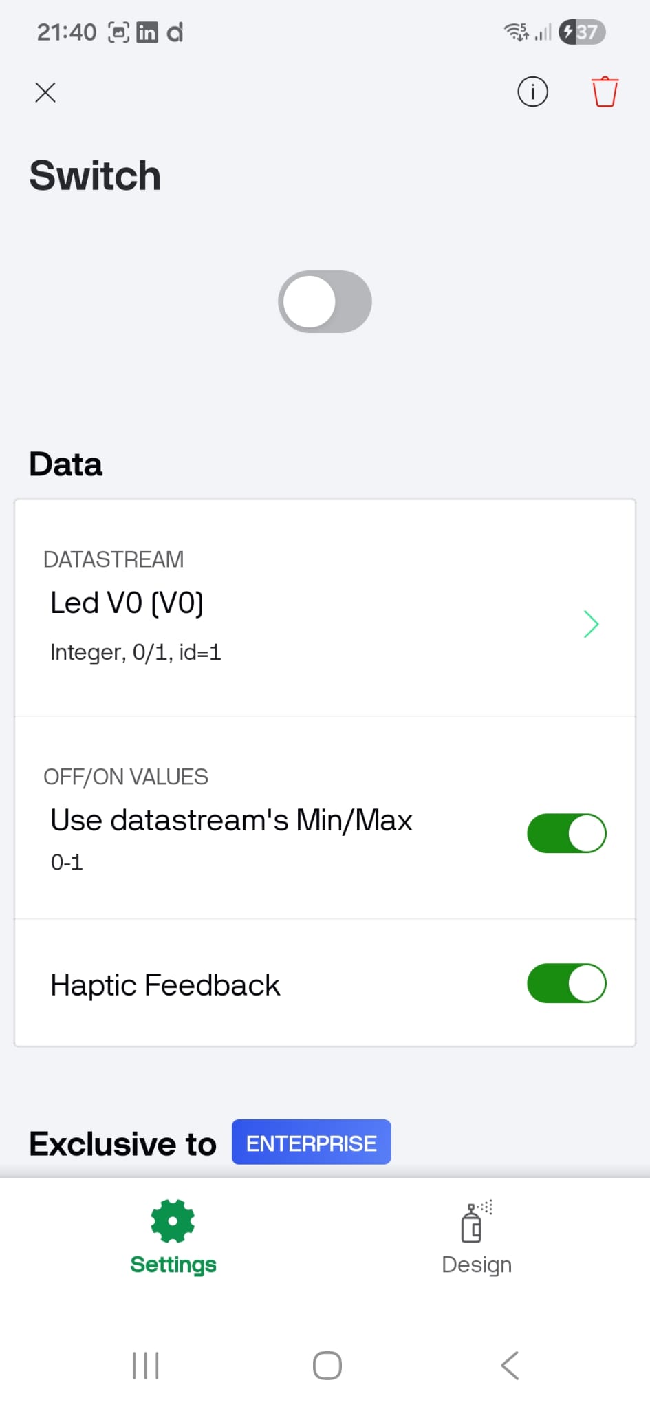
- A Switch: To remotely control a piece of equipment, represented in this prototype by a simple LED.
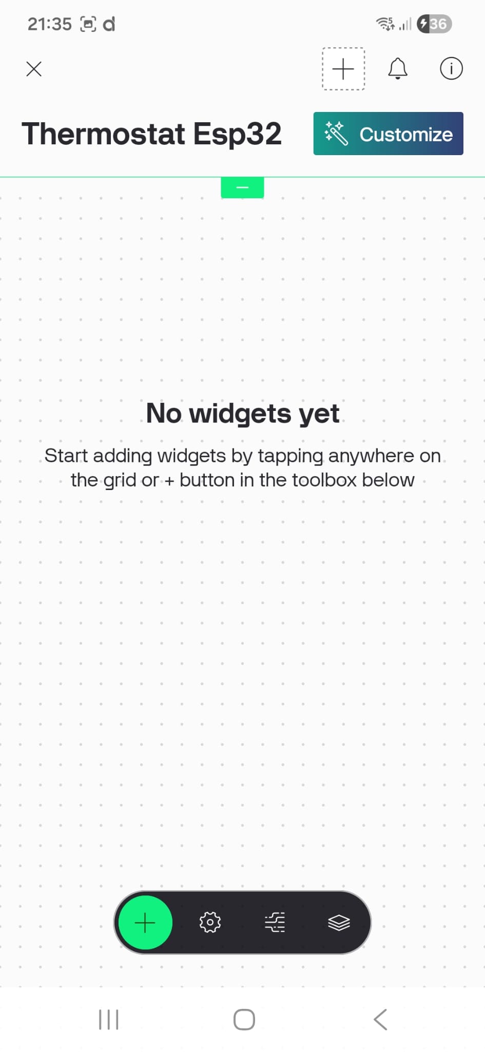
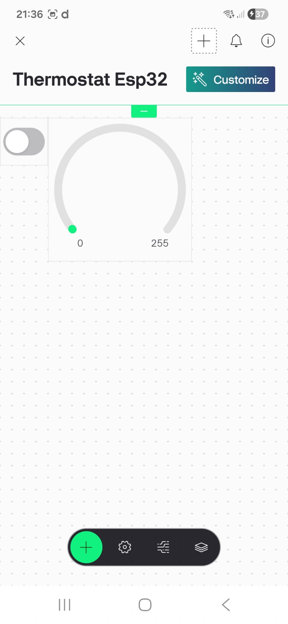
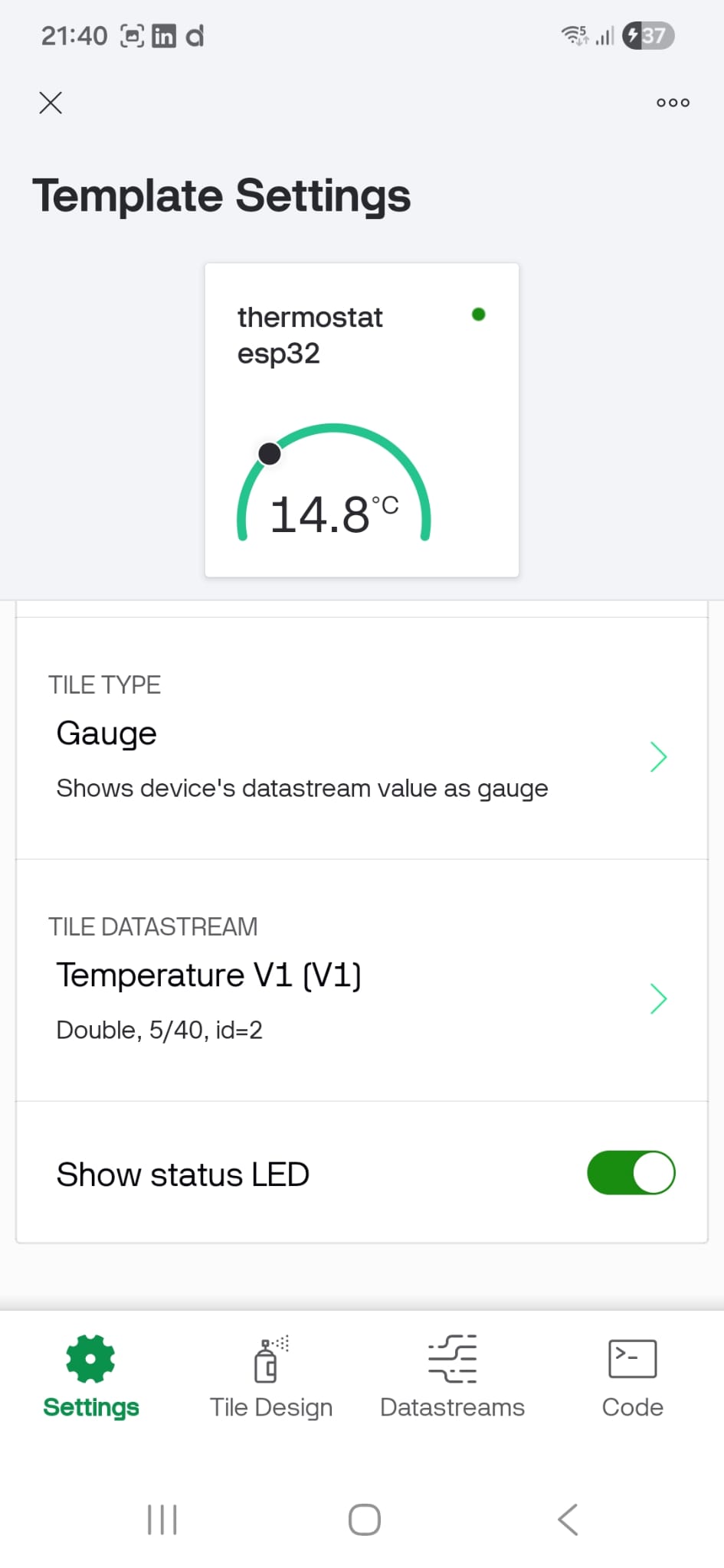
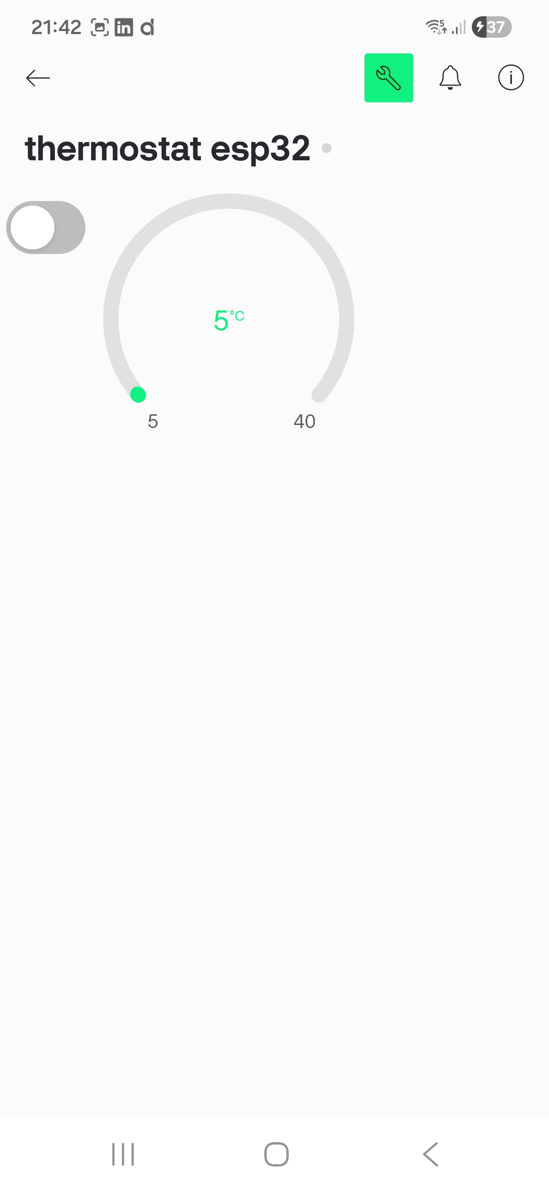
Finally, upon launching the application, our functional Thermostat Dashboard appears:
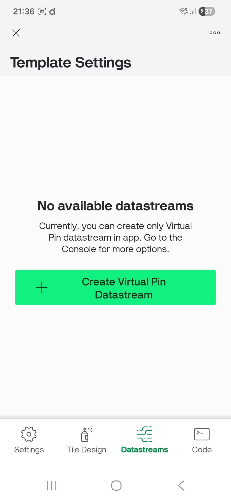
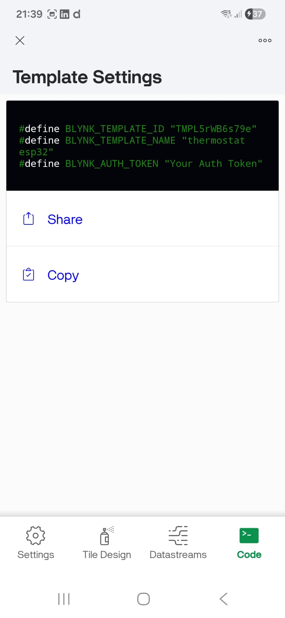
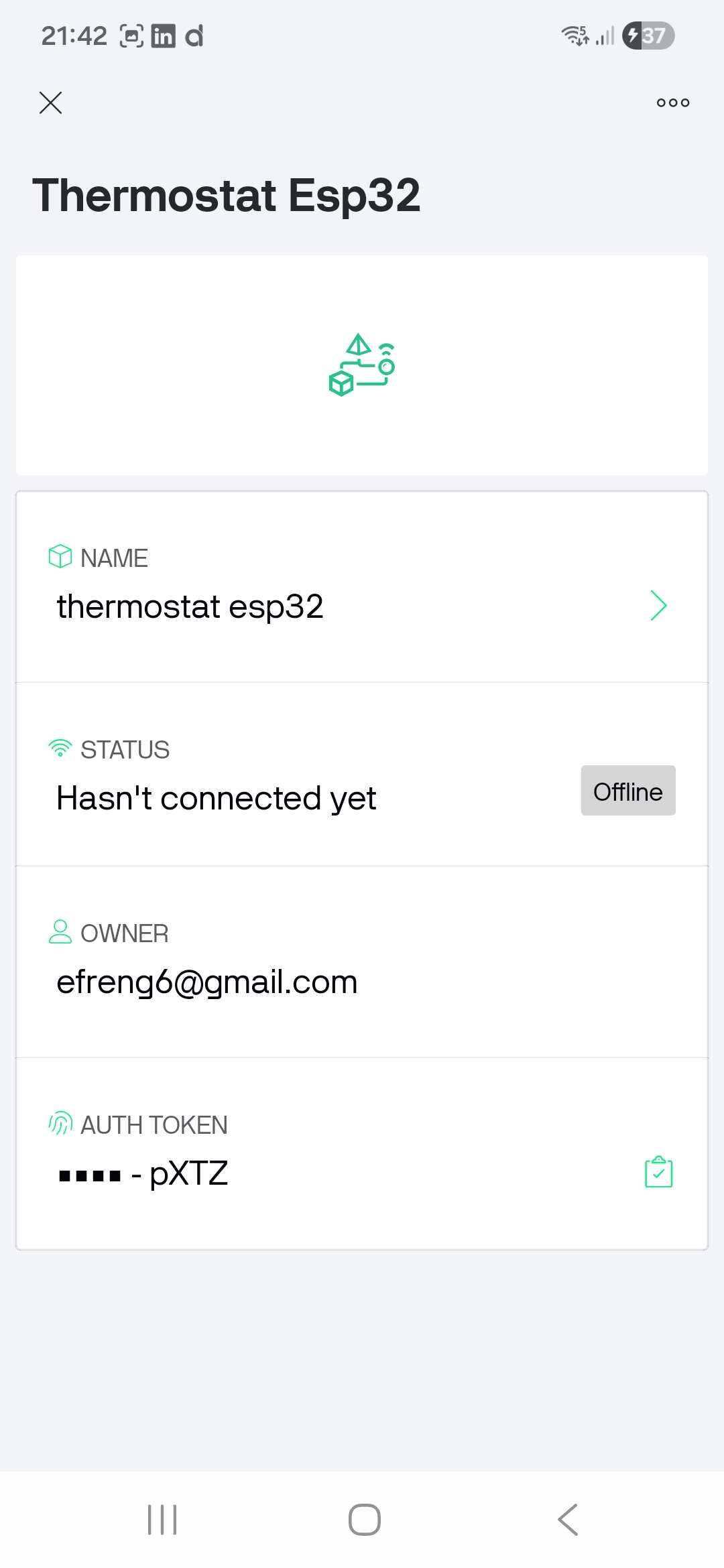
However, once the interface and communication channels are defined, the most critical step is the generation of the Auth Token. This unique identifier serves as the security handshake that bridges the mobile application with the ESP32 firmware.
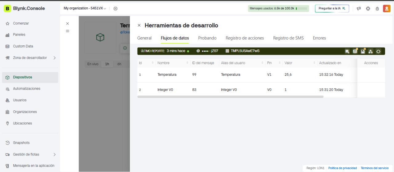
WEB CONSOLE
To verify that the cloud connection is established correctly, we can access the Blynk Cloud Dashboard via a web browser. From there, we can manage the same configurations as in the app and confirm that the data flow is consistent across all platforms.

ARDUINO CODE
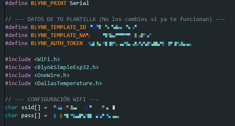
The next step is to program the ESP32 Wrover using the Arduino IDE. We must include three primary configuration parameters provided by Blynk:
- Template ID
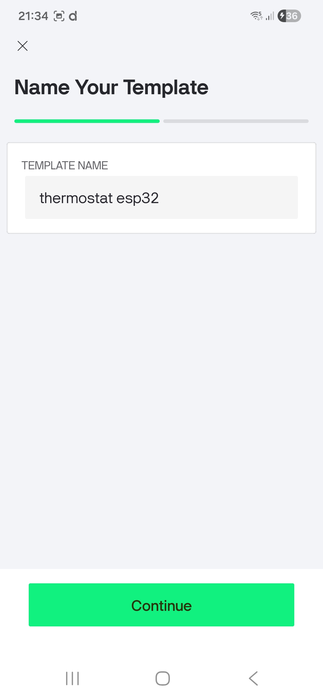
- Template Name
- Auth Token
These values are retrieved from the Blynk app by accessing the 'Device Info' section. Alternatively, as previously shown, they can be found in the Blynk Web Console.
Additionally, we must define two other essential variables: the Wi-Fi SSID (network name) and the Wi-Fi Password to allow the ESP32 to connect to the local network.


As in previous assignments, the Arduino sketch was developed through a collaborative process with Gemini. After explaining the system requirements, connecting an ESP32 Wrover to the Blynk app, transmitting temperature data from a 1-Wire DS18B20 sensor, and controlling the built-in LED remotely, the AI provided the following optimized code:
ESP32 CODE
#define BLYNK_TEMPLATE_ID "..."
#define BLYNK_TEMPLATE_NAME "..."
#define BLYNK_AUTH_TOKEN "..."
#include
#include
#include
#include
#include
// --- NETWORK CONFIGURATION ---
char ssid[] = "...";
char pass[] = "...";
const int oneWireBus = 4; // Data pin for the DS18B20 temperature probe
const int pinLED = 2; // Onboard LED (usually blue on ESP32 DevKits)
OneWire oneWire(oneWireBus);
DallasTemperature sensors(&oneWire);
BlynkTimer timer;
// --- SENSOR READING & DATA TRANSMISSION ---
void sendSensorData() {
sensors.requestTemperatures();
float tempC = sensors.getTempCByIndex(0);
// Check if the sensor is properly connected
if (tempC != DEVICE_DISCONNECTED_C) {
// Send data to Blynk Cloud (Virtual Pin V1)
Blynk.virtualWrite(V1, tempC);
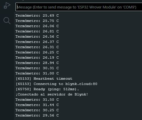
// Serial Monitor feedback for debugging
Serial.print("Sent Temp: ");
Serial.print(tempC);
Serial.println(" °C");
// Visual feedback on the ESP32 (Short blink upon transmission)
digitalWrite(pinLED, HIGH);
delay(100);
digitalWrite(pinLED, LOW);
} else {
Serial.println("Error: Probe not detected. Check wiring/pull-up resistor.");
}
}
// --- REMOTE CONTROL FROM APP (Button on Virtual Pin V2) ---
BLYNK_WRITE(V2) {
int relayState = param.asInt(); // Get integer value from the App widget
// Controls the onboard LED or a relay based on the App button state
digitalWrite(pinLED, relayState);
}
void setup() {
Serial.begin(115200);
pinMode(pinLED, OUTPUT);
sensors.begin(); // Initialize the OneWire sensors
Serial.println("Connecting to Blynk Cloud...");
Blynk.begin(BLYNK_AUTH_TOKEN, ssid, pass);
// Set up a timer to send data every 2 seconds (non-blocking)
timer.setInterval(2000L, sendSensorData);
}
void loop() {
Blynk.run(); // Keeps the Blynk connection alive
timer.run(); // Checks the timer to trigger data transmission
}
To ensure the code compiles and functions correctly, we first had to install the Blynk library via the Arduino Library Manager.
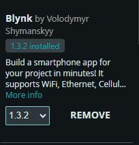
For the ESP32, it is essential to use the official Blynk library developed by Volodymyr Shymanskyy.
While other versions like Khoi Hoang's exist, the official library is the most stable for the Blynk IoT (2.0) platform and natively supports the BLYNK_TEMPLATE_ID definitions.
To install it correctly:
- Go to Tools -> Manage Libraries.
- Search for 'Blynk'.
- Install the version by Volodymyr Shymanskyy (v1.3.x or higher).
This library ensures compatibility with current cloud architecture and provides robust reconnection management—a critical feature for IoT devices.
Blynk library, this project requires the OneWire and DallasTemperature libraries to interface with the DS18B20 digital temperature probe.
FINAL RESULT
The final result and the system's performance can be observed in the following video:
Unfortunately, while the connection was successful and the temperature readings are displayed perfectly on the mobile dashboard, the LED switch did not function as expected.
Although the communication from the switch to the cloud was verified, and both the ESP32 and the Blynk app were synchronized, the LED signal never appeared in the Serial Monitor, and the physical LED remained off.
I will revisit this downlink communication issue in the future to debug the virtual pin trigger.
- Status: Uplink (Sensor to App) Working | Downlink (App to LED) Failing.
- Hypothesis: The
BLYNK_WRITE(V0)function in the firmware might not be matching the Virtual Pin configuration in the Blynk Dashboard, or the specific ESP32 Wrover pin requires a different pull-up configuration. - Future Work: Perform a deep dive into the Blynk
syncAll()functions and verify GPIO 2/built-in LED mapping.
UPDATE AND FINAL SOLUTION
After a few weeks, I came back to the LED issue. After reviewing my previous work, I reached a simple conclusion:
The implementation was actually correct, but I was facing two specific problems:
- Router Firewall Restrictions: As experienced in previous projects, the router was allowing the outgoing temperature data but blocking the incoming LED activation signals. Once I configured the firewall to fix this, the signal went through flawlessly when pressing the button on the Blynk mobile app, finally showing the long-awaited data in the serial monitor.
- Missing Onboard LED: The specific ESP32-WROVER development board I am using does not have an integrated user LED! Therefore, it was physically impossible for anything to light up on the board. After wiring an external LED to Pin 13, it successfully turned on.
Once the LED was mounted on a breadboard with its series resistor and the code was re-uploaded, it worked exactly as expected:
INDIVIDUAL ASSIGNMENT
For this assignment, I reused the PCB I fabricated during the Electronic Production week.
Since the laboratory's milling machine was temporarily unavailable, I used a professional temperature probe designed and provided by my instructor, Adrián. This allowed me to maintain the project's workflow and focus on the data acquisition and interface programming stages.
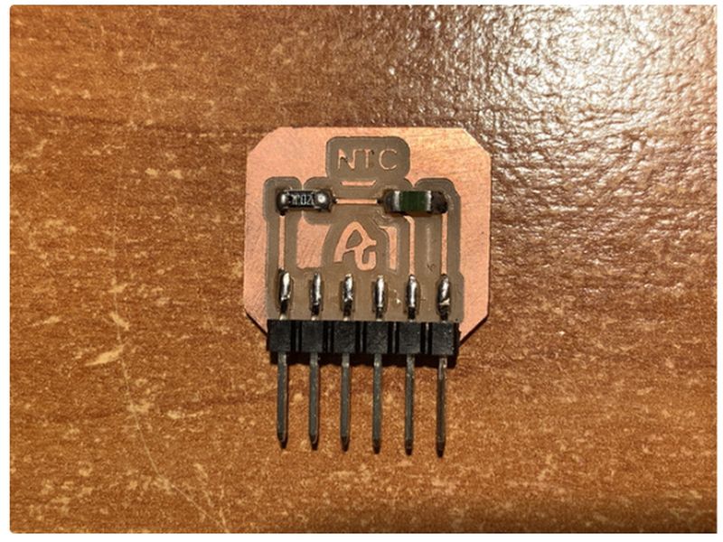
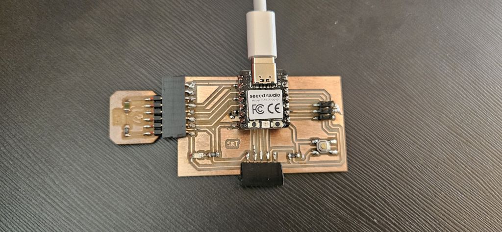
The firmware was developed in the Arduino IDE for the XIAO RP2040. Since the NTC thermistor is an analog sensor, its resistance changes with temperature, creating a variable voltage via the pull-up resistor.
With the probe and the PCB ready, the strategy was to develop a script that allows the XIAO RP2040 to read the sensor's temperature and output the data via the Serial Monitor.
The core objective of this assignment is to bridge the hardware and software by using Processing. This allows us to intercept the raw serial data and transform it into a real-time visual curve, providing a much more intuitive way to monitor temperature fluctuations.
- The Serial Protocol: I established a simple communication protocol where the RP2040 sends the temperature value followed by a newline character (\n) to act as a delimiter.
- The Visual Interface: In Processing, I wrote a sketch that parses these strings, converts them back to floats, and maps them to the Y-axis of the screen to draw the graph.
NTC Sensor → ADC (XIAO RP2040) → Serial Port → Processing IDE → Visual Graph
ARDUINO CODE
As in previous assignments, I leveraged AI to streamline the firmware development.
I used Gemini to generate the Arduino code, providing specific instructions:
The XIAO RP2040 needed to read the NTC probe connected to pin A0 and output the processed data via the Serial Monitor.
The AI produced a highly accurate script that worked on the first attempt, correctly implementing the ADC-to-temperature conversion logic.
Arduino ID Code
#include

const int pinNTC = A0;
const int B = 3950;      // Beta coefficient (standard for most 10k NTC thermistors)
const int R0 = 10000;    // Resistance of the NTC at 25°C (Room temperature)

void setup() {
  Serial.begin(115200);

  // Set ADC resolution to 12-bit (0-4095 range) for better precision
  // Common for modern boards like Seeed Studio Xiao or ESP32
  analogReadResolution(12);
}

void loop() {
  int val = analogRead(pinNTC);

  // Calculate resistance based on the analog reading (voltage divider)
  // Assuming a pull-up configuration on the analog pin
  float resistance = (float)(4095 - val) * R0 / val;

  // Steinhart-Hart equation (Beta-model approximation)
  // 1. Calculate temperature in Kelvin
  // 2. Convert Kelvin to Celsius (-273.15)
  float temperature = 1 / (log(resistance / R0) / B + 1 / 298.15) - 273.15;

  // Stream the temperature value via Serial for Processing to parse
  Serial.println(temperature);

  delay(200); // Sampling rate (approx. 5Hz)
}
The generated code included the specific Beta coefficient for the thermistor and handled the 12-bit resolution of the RP2040's ADC, ensuring the mathematical model matched my hardware perfectly.
Unlike standard Arduino boards (10-bit ADC), the Seeed XIAO RP2040 operates with a 12-bit resolution. This means the analog values range from 0 to 4095 instead of 0 to 1023. By adjusting the firmware to this scale, the temperature calculation becomes 4 times more precise, minimizing the "steppy" jumps in the visual curve during the Programming stage.
After uploading the firmware to the XIAO and verifying the data in the Serial Monitor, I opened Processing to create the interface. This software receives the serial data and converts it into visual coordinates.
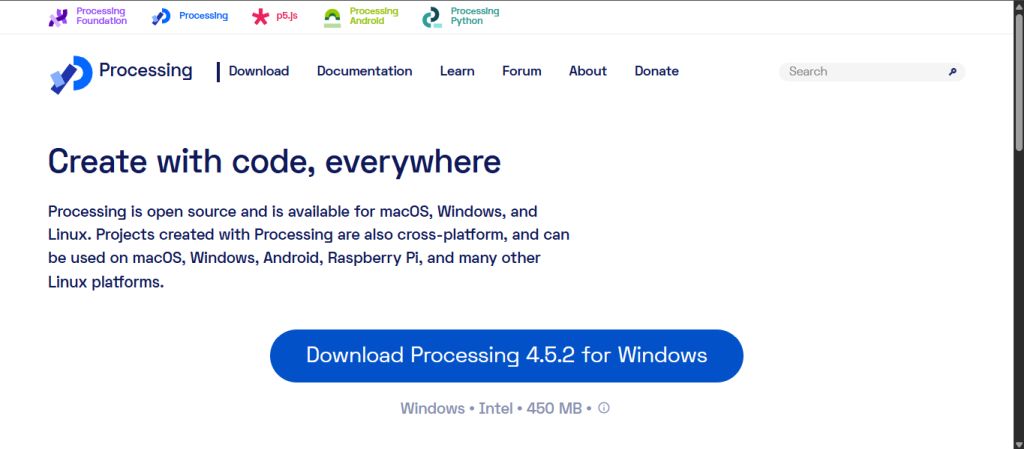
PROCESSING
The first step was to install Processing, which I downloaded and set up from its official website.
Following the same workflow as with Arduino, I used Gemini to generate a Processing script. My requirement was to create an interface that could parse the incoming temperature data from the serial port and plot it as a real-time graph.
The first version of the code generated by the AI was the following:
Processing ID Code 1
import processing.serial.*;

Serial myPort;
float temp = 0;
float[] history; // Array to store historical data points for the graph

void setup() {
  size(800, 400);
  history = new float[width]; // Initialize the array based on screen width

  // List available serial ports in the console
  printArray(Serial.list());

  // Ensure the correct index is selected for your Xiao or microcontroller
  try {
    myPort = new Serial(this, Serial.list()[0], 115200);
    myPort.bufferUntil('\n'); // Generate a serialEvent when a newline arrives
  } catch (Exception e) {
    println("Serial Port Error: Check your connection and index.");
  }
}

void draw() {
  background(20);
  drawGrid(); // Call helper function to draw the background grid

  // Draw the temperature trend line
  stroke(0, 255, 200);
  strokeWeight(2);
  noFill();
  beginShape();
  for (int i = 0; i < history.length; i++) {
    // Map the temperature range (0°C - 50°C) to the window height
    // Note: Y-axis is inverted in Processing (0 is top)
    float y = map(history[i], 0, 50, height, 0);
    vertex(i, y);
  }
  endShape();

  // Display current numerical value
  fill(255);
  textSize(32);
  text(nf(temp, 0, 1) + " °C", 20, 50);
}

// Handler for incoming serial data
void serialEvent(Serial p) {
  String inString = p.readStringUntil('\n');
  if (inString != null) {
    temp = float(trim(inString));

    // Shift historical data to the left to create a scrolling effect
    for (int i = 0; i < history.length - 1; i++) {
      history[i] = history[i+1];
    }
    // Add the newest reading to the end of the array
    history[history.length - 1] = temp;
  }
}

// Background visualization helper
void drawGrid() {
  stroke(50); // Subtle grey for the grid lines
  for (int i = 0; i < height; i += 50) {
    line(0, i, width, i);
  }
}
The final outcome of the integration between the Seeed XIAO RP2040, the custom PCB, and the Processing interface is showcased below. The graph accurately reflects the real-time thermal changes detected by the NTC probe.
After reviewing the initial results, I decided to push the interface further.
I discussed a new concept with Gemini: Instead of a linear graph, I wanted a circular gauge, similar to a car's tachometer, featuring a dynamic arc that grows and changes color based on the temperature.
The AI also suggested integrating a real-time digital readout in the center. The result was a much more intuitive and professional dashboard.
Processing ID Code 2
import processing.serial.*;

Serial myPort;
float temp = 0;
float smoothedTemp = 0;

// Gauge configuration settings
float cx, cy;
float diameter;
float startAngle = PI + QUARTER_PI;
float endAngle = TWO_PI + PI - QUARTER_PI;
float minTemp = 20;
float maxTemp = 50;

void setup() {
  size(800, 600);
  smooth(8); // Anti-aliasing for smoother graphics

  cx = width / 2;
  cy = height / 2 + 50;
  diameter = width * 0.65;

  // List available serial ports
  printArray(Serial.list());

  // REMINDER: Change the index [0] to match your specific port if it doesn't connect
  try {
    myPort = new Serial(this, Serial.list()[0], 115200);
    myPort.bufferUntil('\n'); // Wait for a newline character to trigger serialEvent
  } catch (Exception e) {
    println("Error: Could not open the port. Check the index [0, 1, 2...]");
  }

  background(15);
}

void draw() {
  background(15); // Clear the frame every cycle

  // 1. Movement smoothing (Linear Interpolation)
  smoothedTemp = lerp(smoothedTemp, temp, 0.08);

  // 2. Draw the gauge BACKGROUND arc (Dark grey)
  noFill(); // <--- CRITICAL: Prevents solid fill distortion
  strokeWeight(45);
  stroke(40);
  strokeCap(ROUND);
  arc(cx, cy, diameter, diameter, startAngle, endAngle);

  // 3. Draw visual markers (Ticks and numbers)
  drawMarkers();

  // 4. Draw the PROGRESS BAR (Dynamic color feedback)
  float tempAngle = map(smoothedTemp, minTemp, maxTemp, startAngle, endAngle);
  tempAngle = constrain(tempAngle, startAngle, endAngle);

  // Color calculation (Transition Blue -> Red)
  float colorRatio = map(smoothedTemp, minTemp, maxTemp, 0, 1);
  colorRatio = constrain(colorRatio, 0, 1);
  color barColor = lerpColor(color(0, 100, 255), color(255, 40, 0), colorRatio);

  // Draw the colored data arc
  noFill();
  stroke(barColor);
  strokeWeight(45);
  if (smoothedTemp > minTemp) {
    arc(cx, cy, diameter, diameter, startAngle, tempAngle);
  }

  // 5. Aesthetic glow (Thin outer stroke)
  strokeWeight(2);
  stroke(255, 30);
  arc(cx, cy, diameter + 55, diameter + 55, startAngle, endAngle);

  // 6. Central numeric display
  drawNumericDisplay(barColor);
}

void drawMarkers() {
  int numMarkers = 7;
  for (int i = 0; i < numMarkers; i++) {
    float angle = map(i, 0, numMarkers - 1, startAngle, endAngle);
    float labelTemp = map(i, 0, numMarkers - 1, minTemp, maxTemp);

    float rOuter = diameter / 2 + 20;
    float rInner = diameter / 2 - 20;

    stroke(80);
    strokeWeight(3);
    line(cx + cos(angle)*rInner, cy + sin(angle)*rInner, cx + cos(angle)*rOuter, cy + sin(angle)*rOuter);

    // Labels/Numbers
    fill(120);
    textAlign(CENTER, CENTER);
    textSize(18);
    float rText = diameter / 2 + 50;
    text(int(labelTemp) + "°", cx + cos(angle)*rText, cy + sin(angle)*rText);
  }
}

void drawNumericDisplay(color c) {
  // Container box for the value
  fill(0, 100);
  noStroke();
  rectMode(CENTER);
  rect(cx, cy - 30, 220, 110, 15);

  // Temperature value string
  fill(255);
  textSize(70);
  textAlign(CENTER, CENTER);
  text(nf(smoothedTemp, 0, 1), cx - 20, cy - 40);

  // Unit label
  fill(c);
  textSize(30);
  text("°C", cx + 70, cy - 30);

  // Title/Caption
  fill(100);
  textSize(14);
  text("AMBIENT TEMPERATURE", cx, cy + 10);
}

// Serial Communication Handler
void serialEvent(Serial p) {
  String inString = p.readStringUntil('\n'); // Read incoming serial buffer
  if (inString != null) {
    inString = trim(inString); // Remove whitespace/newlines
    float m = float(inString); // Convert string to float
    if (!Float.isNaN(m)) {
      temp = m; // Update global temperature variable
    }
  }
}
This second iteration provided a much richer user experience. Here is the video showing the final functional dashboard:
Final UI design in Processing. The circular gauge dynamically fills as the NTC probe detects heat, with the color gradient providing immediate thermal feedback.
It went from a simple science experiment look to a professional industrial monitor in just one iteration thanks to the AI assistance.
UPDATED COLOR SCHEME
Processing ID Code 3
import processing.serial.*;

Serial myPort;
float temp = 0;
float smoothedTemp = 0;

// Gauge Configuration
float cx, cy;
float diameter;
float startAngle = PI + QUARTER_PI;
float endAngle = TWO_PI + PI - QUARTER_PI;
float minTemp = 20;
float maxTemp = 50;

void setup() {
  size(800, 600);
  smooth(8); // Anti-aliasing for better UI quality

  cx = width / 2;
  cy = height / 2 + 50;
  diameter = width * 0.65;

  // List available serial ports
  printArray(Serial.list());

  // Initialize Serial communication
  try {
    // Adjust the index [0] to match your specific port
    myPort = new Serial(this, Serial.list()[0], 115200);
    myPort.bufferUntil('\n');
  } catch (Exception e) {
    println("Error: Could not open serial port. Check the index [0, 1, 2...]");
  }

  background(15);
}

void draw() {
  background(15); // Refresh background every frame

  // 1. Movement smoothing (Linear Interpolation)
  smoothedTemp = lerp(smoothedTemp, temp, 0.08);

  // 2. Draw Gauge Background (Dark grey arc)
  noFill();
  strokeWeight(45);
  stroke(40);
  strokeCap(ROUND);
  arc(cx, cy, diameter, diameter, startAngle, endAngle);

  // 3. Draw UI Markers (Ticks and labels)
  drawMarkers();

  // 4. Draw Progress Bar (Dynamic color)
  float tempAngle = map(smoothedTemp, minTemp, maxTemp, startAngle, endAngle);
  tempAngle = constrain(tempAngle, startAngle, endAngle);

  // Color calculation
  float colorRatio = map(smoothedTemp, minTemp, maxTemp, 0, 1);
  colorRatio = constrain(colorRatio, 0, 1);

  /*
     UPDATED COLOR SCHEME:
     From Yellow (255, 200, 0) to Green (0, 255, 100).
     Changed to provide a different visual feedback compared to the previous Blue-Red scale.
  */
  color barColor = lerpColor(color(255, 200, 0), color(0, 255, 100), colorRatio);

  // Draw the active colored arc
  noFill();
  stroke(barColor);
  strokeWeight(45);
  if (smoothedTemp > minTemp) {
    arc(cx, cy, diameter, diameter, startAngle, tempAngle);
  }

  // 5. Aesthetic glow (Fine outer line)
  strokeWeight(2);
  stroke(255, 30);
  arc(cx, cy, diameter + 55, diameter + 55, startAngle, endAngle);

  // 6. Center Numeric Display
  drawNumericDisplay(barColor);
}

void drawMarkers() {
  int numMarkers = 7;
  for (int i = 0; i < numMarkers; i++) {
    float angle = map(i, 0, numMarkers - 1, startAngle, endAngle);
    float labelTemp = map(i, 0, numMarkers - 1, minTemp, maxTemp);

    float rOuter = diameter / 2 + 20;
    float rInner = diameter / 2 - 20;

    stroke(80);
    strokeWeight(3);
    line(cx + cos(angle)*rInner, cy + sin(angle)*rInner, cx + cos(angle)*rOuter, cy + sin(angle)*rOuter);

    // Labels
    fill(120);
    textAlign(CENTER, CENTER);
    textSize(18);
    float rText = diameter / 2 + 50;
    text(int(labelTemp) + "°", cx + cos(angle)*rText, cy + sin(angle)*rText);
  }
}

void drawNumericDisplay(color c) {
  // Number background box
  fill(0, 100);
  noStroke();
  rectMode(CENTER);
  rect(cx, cy - 30, 220, 110, 15);

  // Temperature value
  fill(255);
  textSize(70);
  textAlign(CENTER, CENTER);
  text(nf(smoothedTemp, 0, 1), cx - 20, cy - 40);

  // Units
  fill(c);
  textSize(30);
  text("°C", cx + 70, cy - 30);

  fill(100);
  textSize(14);
  text("AMBIENT TEMPERATURE", cx, cy + 10);
}

void serialEvent(Serial p) {
  // Read incoming string until newline
  String inString = p.readStringUntil('\n');
  if (inString != null) {
    inString = trim(inString);
    float m = float(inString);
    // Validate that the received data is a number
    if (!Float.isNaN(m)) {
      temp = m;
    }
  }
}
After reviewing the code, I decided to modify a minor parameter, such as the graph color, to test the system's responsiveness and ensure the interface was updating correctly.
AI Collaboration & Code Generation Insights
To obtain the Arduino code shared above, I collaborated with AI, specifically using Gemini. However, there is no single, specific prompt used to generate the code. Instead, the process relies on an ongoing, natural dialogue where I explain the logical ideas and specific tasks I want the microcontroller to execute.
Furthermore, with the memory and past activity features enabled, Gemini retains the context of previous project developments and adapts to my workflow preferences. As a result, the AI often anticipates my technical requirements, occasionally proposing relevant code structures even before they are explicitly requested.
KEY CONCEPTS IN PROCESSING
1. The draw() loop
- What it is: This is a built-in function that runs continuously and sequentially (by default at 60 frames per second) right after the initial setup() function is executed.
- Why it matters: It acts as the "heart" of the graphical user interface. Running in a continuous loop allows the screen to refresh in real time, making it essential for creating animations, rendering dynamic graphics, and constantly updating visual representations of incoming sensor data.
2. The serialEvent() handler
- What it is: This is a specialized interrupt function that is automatically triggered only when new data becomes available at the designated serial port (sent by the microcontroller).
- Why it matters: Instead of cluttering the main draw() loop by constantly polling or asking if new data has arrived, Processing listens quietly in the background. As soon as a data packet arrives, serialEvent() captures and processes it efficiently, preventing lags or freezing in the user interface.
3. The Coordinate System
- What it is: In Processing, the window's origin coordinate (0,0) is located at the top-left corner. The X-axis increases to the right, while the Y-axis increases downward.
- Why it matters: This layout can feel a bit counterintuitive initially if you are used to the traditional Cartesian coordinate system where the Y-axis increases upward. Understanding this structure is crucial for properly positioning visual elements, shapes, text, or progress bars without them clipping out of the screen.
4. The map() function
- What it is: A powerful built-in mathematical tool that proportionally translates a value from its original range to a new target range. Its standard syntax is:
- Why it matters: It is highly valuable for user interface scaling. For instance, if a microcontroller reads raw analog sensor data ranging from 0 to 1023, but the visual graph on your screen is only 400 pixels wide, map() scales that input automatically (e.g., a reading of 512 scales directly to 200 pixels), eliminating the need for manual rule-of-three calculations.
map(value, start1, stop1, start2, stop2)
CONCLUSION
While I found the content of this assignment highly engaging, time constraints limited my ability to explore it as deeply as I would have liked.
What surprised me the most and presented a challenge at first was changing my mindset regarding the inverted Y-axis in the coordinate system.
However, combining serialEvent() to manage data asynchronously with the power of the map() function made transitioning from raw microcontroller data to a fluid visual representation much faster than I expected.
To develop the interface, I leveraged Gemini to draft the initial code, which I later analyzed and modified to test different behaviors. Additionally, I have identified areas for further study regarding the communication protocols between Blynk’s cloud services and the data flow between the router and the ESP32.
While these represent more advanced networking concepts, I plan to revisit them later to fully master the architecture. For now, I am moving forward with the Fab Academy schedule.