WEEK 11 NETWORKING AND COMMUNICATIONS
- INTRODUCTION
- SCHEDULE
- TOOLCHAIN
- GROUP ASSIGNMENT
- INDIVIDUAL ASSIGNMENT
- I2C COMMUNICATION
- UDP DATA TRAFFIC
- BLUETOOTH CONNECTION - BLE Connection
- DIRECT WI-FI CONNECTION WITH A TEMPERATURE PROBE
- CONCLUSION
- ORIGINAL FILES
INTRODUCTION
In this week's assignment we have to work on the interconnection between different controllers, so that they can "talk" and understand each other by sending and receiving information and commands, and then execute those commands and return information.
To carry out this work, I have several devices:
- Two Xiao RP2040 integrated into two PCBs, one of them manufactured by myself.
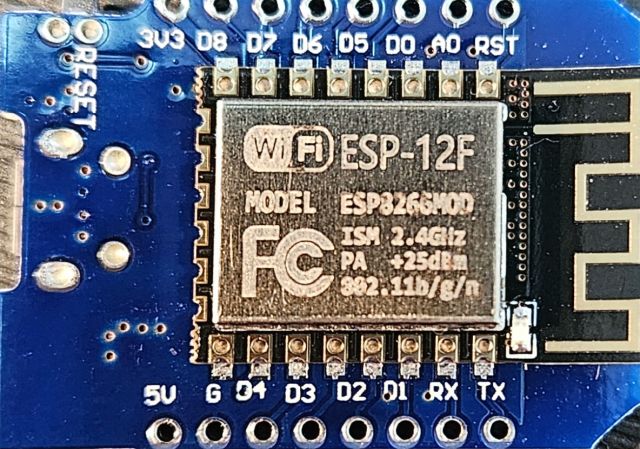
- Two Wemos ESP12F
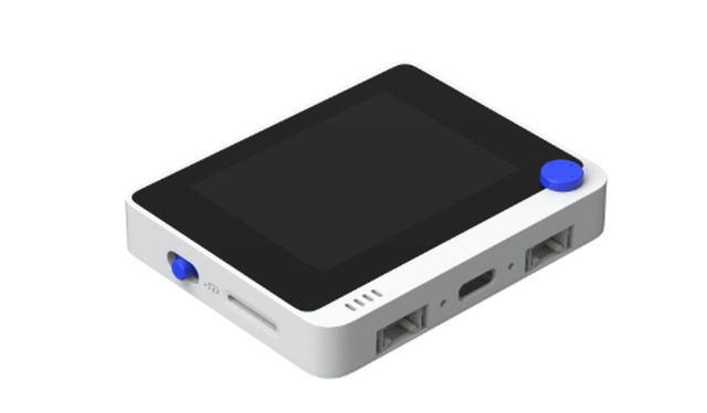
- One Wio Terminal D51R
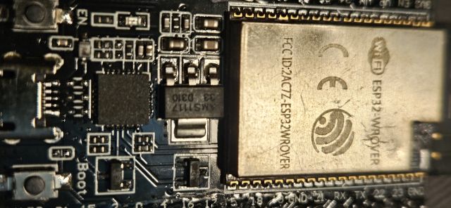
- One ESP32 Wrover
As in previous weeks, the assignment is divided into Individual and Group assignment. However, I have structured this documentation based on the different communication protocols explored, addressing each of them individually.
It is useful to differentiate the different types of connection that exist. There are many, but we can separate them into five groups:
- UART: This is a wired and very basic connection that allows connecting two devices using two pins, TX and RX.
- Master – Slave: In this type of connection we include I2C, SPI and other BUS-based communications. They are wired and can connect several devices.
- Client – Server: Wireless connection where clients request information from servers, establishing communication between them. Typical HTTP connections are an example.
- Publish – Subscribe: This is the type of connection implemented in this part of the assignment, an MQTT connection. In this type of communication there is a broker that emits certain data, defined by the broker itself, and subscribers that can connect to the broker and "listen" to these data streams. Communication is not bidirectional; the broker publishes and the subscribers listen.
- Broadcast: Similar to the previous one, but in this case the transmitting node emits the message and everyone receives it without the need for subscription. A typical example of this type of network is radio or television.
The multiple types of communication that exist can initially be separated into Wired and Wireless communications. Therefore, in order to test and understand the main types of communication, the idea is:
- To connect the Wio Terminal to an MQTT network to subscribe to and receive data sent by a classmate's broker (GROUP ASSIGNMENT)
- To connect the two Xiao RP2040 and an OLED display in an I2C wired network (INDIVIDUAL ASSIGNMENT)
- To connect the Wemos and the Wio wirelessly via WiFi (INDIVIDUAL ASSIGNMENT)
- To connect the Wrover and the Wio wirelessly via Bluetooth (INDIVIDUAL ASSIGNMENT)
- To connect the Wrover and the Wio Terminal directly via WiFi, establishing a local network without the need for an external router or infrastructure (INDIVIDUAL ASSIGNMENT)
This approach allowed me to test the following protocols which, represent the most common communication standards used in the industry today:
- Cloud architecture (MQTT) (Publish-Subscribe)
- Wired communication (I2C) (Master-Slave)
- Direct local network (UDP)
- Bluetooth Low Energy (BLE)
- WiFi in Access Point mode (Client-Server)
SCHEDULE
This week has been unique because of the Holy Week (Semana Santa) holidays, which gave me four free days to complete the assignment. I could hardly enjoy the festivities, but in exchange, this project has allowed me to learn a great deal.
- Thursday: On Thursday morning, we held the videoconference to explain the assignment. From that point on, I spent the rest of the day understanding the requirements, and by the end of the day, I had already successfully implemented the wired networks.
- Friday: I dedicated the entire day on Friday, except for my lunch break, to working on MQTT networks and part of the UDP setups.
- Saturday: Saturday was an intense day. I finished working on the UDP networks, struggled a bit with Bluetooth, and fortunately, the Wi-Fi Direct setup went so smoothly that I was actually able to go out for dinner with friends.
- Sunday: Finally, Sunday was dedicated to the most important part of Fab Academy: Documentation!
TOOLCHAIN
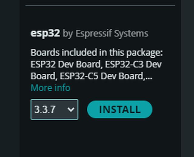
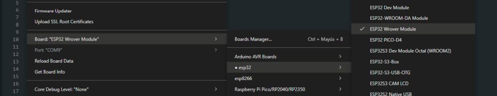
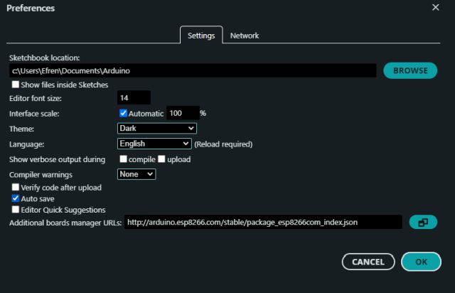
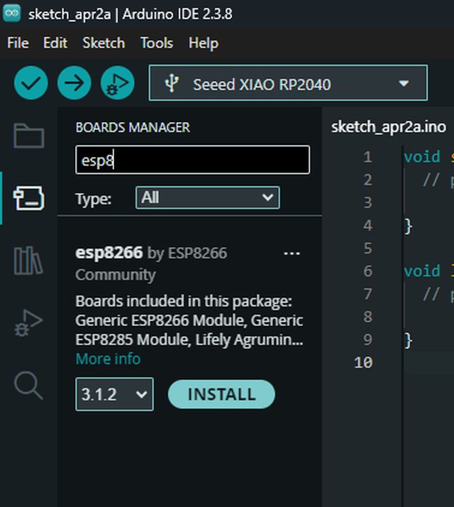
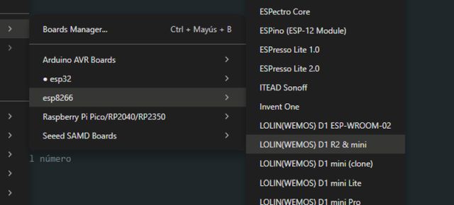
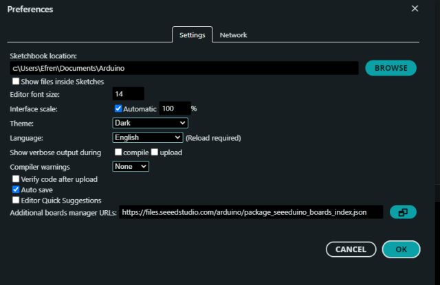
Since I am going to work with new controllers, not only the RP2040 that I have been using so far, the first step is to prepare my Arduino IDE with new tools. To do this, I have to install the board packages for the Wemos ESP12F, the ESP32 Wrover and the Wio Terminal D51R.
For the Wrover, I only needed to install it from the Arduino IDE board manager database, but for the Wemos, just as happened with the RP2040, I had to import the board definitions manually, in this case from the website Luis Llamas
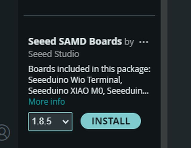
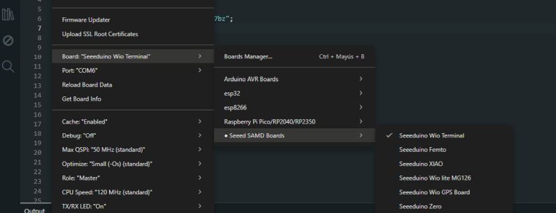
At the same time, I had to do the same to install the board package for the Wio Terminal. The procedure is the same as when I had to do it previously with the Xiao boards. In this case I used the website Seeedstudio
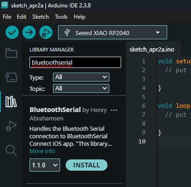
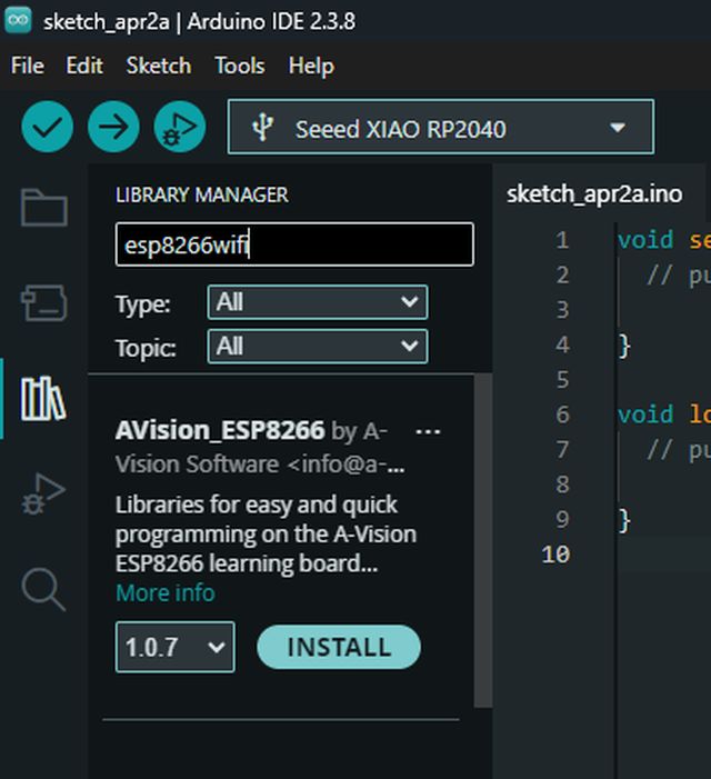
Later, since I am going to work with Bluetooth and WiFi, I also had to install the libraries Avision_esp8266 and Seeed Arduino rpcBLE
BOARDS
I already had the ESP32 loaded in the Arduino IDE board manager.
The Wemos board was not included in the Arduino IDE database, so I had to download it.
The Wio Terminal board also had to be downloaded from the internet.
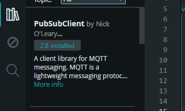
LIBRARIES
GROUP ASSIGNMENT
FabLab Leon work groupMQTT CONNECTION
For the group assignment, Oscar, one of my classmates, deployed an MQTT server that sends data from his photovoltaic installation. The idea is to subscribe to his broker and receive this data.
For the implementation of this assignment, I used a commercial device, a Wio Terminal D51R equipped with an ATSAMD51 processor and a 40-pin header compatible with the Raspberry Pi. All the information, including the required toolchain to work with this device, was obtained from the Seeedstudio website.
Once I had my Arduino IDE set up with the necessary toolchain, I was able to start developing the code. As always, this was thanks to the invaluable help of Gemini and ChatGPT; after encountering several issues with the Wio screen and doing some research, I realized I had mistakenly installed two libraries TFT_eSPI and Grove – LCD RGB. This created a conflict with the Seeed_Arduino_LCD library that comes pre-installed on the Wio Terminal itself. It wasn't until I uninstalled those two libraries that I finally managed to get the screen to display anything.
From this point on, I was able to develop the necessary code to subscribe the Wio to the broker and display the data on the screen. However, as with any MQTT subscription, several key details are required:
- Broker Connection Data:
- IP Address: The foundation of any subscription; it identifies the broker we want to connect to.
- Access Port: 1883 is the standard, although others may be used.
- Client ID: A unique code for each client. If one is not selected, it is assigned automatically.
- Username and Password: The broker uses these credentials to decide who is granted access.
- Subscription Data:
- Topics: These are the specific data streams we choose to monitor from those broadcast by the broker.
- Quality of Service (QoS), which can be:
- 0: No confirmation (At most once).
- 1: With confirmation (At least once).
- 2: Guaranteed (Exactly once).
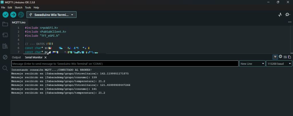
Once these details are entered, we only need to provide the Wi-Fi credentials for the network we will be using, and the Wio Terminal is ready—subscribed and receiving data from the broker.
As you can see, this type of connection is designed solely to receive the data we are subscribed to; we cannot interact with the broker, only "listen" to it.
WEMOS D1 MINI ESP12F AS AN MQTT PUBLISHER
Next, I am going to create another publisher connected to the same broker. This means we will be sending our own data to the same MQTT server, using the same IP address: 89.116.24.168. In this way, acting as a universal repeater, the server will receive the data it was already getting from my colleague's installation, and in addition, it will receive the data I am going to send. Consequently, anyone subscribed to that MQTT network will now receive both sets of data.
For the publisher, I have chosen a Wemos D1 with an ESP12F controller. As on previous occasions, we must download the necessary toolchain to program it.
Once programmed and transmitting, I was able to verify how the real data from my colleague's photovoltaic installation and the "fake" data I was sending were being superimposed on the Wio Terminal. Just like me, anyone subscribed to the broker would see Oscar's solar production generating 170W at midnight!!
INDIVIDUAL ASSIGNMENT
I2C COMMUNICATION
The three most important types of Wired communication that exist are:
UART (Serial)
UART is a point-to-point communication that requires two pins on each device and two wires to connect them (TX/RX). It is a simple and functional connection, but it only allows connecting two devices to each other.
SPI
SPI is a very fast communication protocol, but it requires four pins. It can connect several devices, but in a star configuration, where one device is the master and the others are slaves. The MOSI, MISO and SCK pins can be shared with all slaves, forming the network backbone using three wires, but the CS wire must be unique for each slave, requiring as many pins on the master as slaves connected to the network.
I2C
I2C is not as fast as SPI, but like UART it only requires two pins on each device and two wires for the entire network. It can connect several devices in parallel, where the two wires run from one device to another interconnecting the SDA (serial data) and SCL (serial clock) pins of each device.
However, just like SPI, there is one master and the rest are slaves. The difference is that when the master wants to communicate with a specific slave, instead of selecting the corresponding CS pin for that slave (hardware selection), a hexadecimal address is selected in the communication protocol (software selection) corresponding to that slave. Even though all devices share the wiring, each slave has its own unique address.
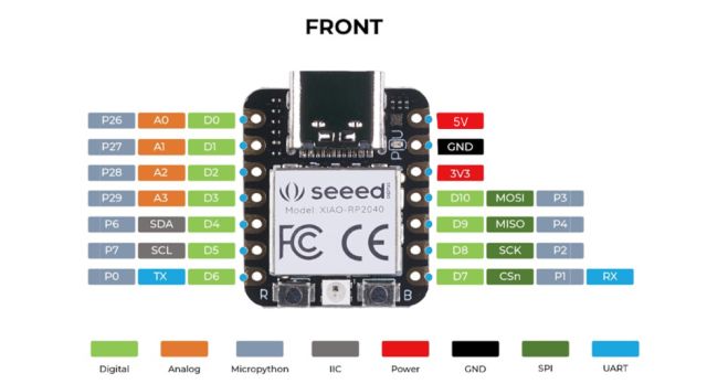
In my case, I used I2C communication between the Xiao RP2040 for three reasons:Pin limitation
The Xiao RP2040 only has 11 GPIO pins. Implementing a network using SPI would have forced me to dedicate five pins (SCK, MISO, MOSI + 2CS). With I2C, I only need two pins (SDA and SCL) to control both the communication between boards and the OLED display.
Ease of expansion
In I2C, adding the display was "free" in terms of wiring, since it connects to the same bus. In SPI, I would have had to find an extra pin for the display Chip Select.
Pin status
Since the pins assigned to SCK and MISO, as well as TX and RX, were already occupied by other critical functions in the design, using SPI or UART was physically impossible without a complete redesign of the board or wiring.
Two Xiao RP2040
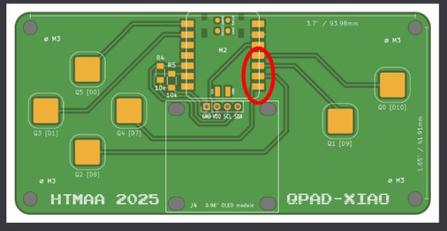
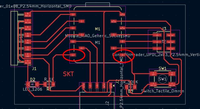
Initially, I connected two PCBs with their respective RP2040 through I2C. The PCBs are the Qpad – Xiao that I had already worked with previously and my own custom-made SKT board.
The physical connection is therefore simple: connect the SCL and SDA pins of both PCBs together along with a GND pin to stabilize the voltage between both boards.
Next, both Xiao boards have to be programmed separately, one as master (the Qpad) and the other as slave (the SKT).
The key point in I2C interconnections is to assign each slave device a unique hexadecimal address, so that even though the physical connection is shared by all devices, the master can communicate with each slave independently using that address.
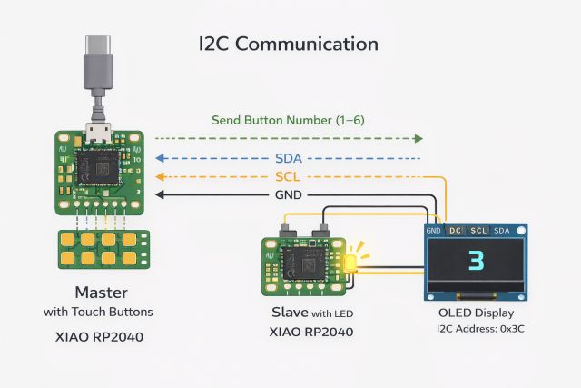
I programmed each Xiao so that the master Xiao requests the slave Xiao to turn on the LED integrated in its PCB as many times as the button number pressed on the master PCB. In this way, the master Xiao receives the information about which button has been pressed on the board where it is integrated, and sends the command to the slave Xiao to blink the LED the corresponding number of times.
Two Xiao and one OLED
Once I confirmed that the connection works, I added a third device to the network, an OLED display. The connection remains the same: the OLED display is connected in parallel to the same SCL and SDA lines along with GND. In this way, if we wanted to incorporate more devices, we would continue doing the same, creating a common three-wire line and connecting all the devices we need to it.
The only difference in this case is that, obviously, we had to power the display using a 3.3V line obtained from the slave PCB. The Xiao boards are already powered through their USB ports.
The key now lies in the programming. The slave Xiao configuration remains the same, since we had already assigned it the address 0x08. Now in the master Xiao we have to add a second device, the OLED display, to which we assign a different address, 0x3C. In this way, when the master Xiao sends the code for the LED, it does so to the slave Xiao address, while when it sends the code to the display, it does so to the display address.
Master code
#include
#include
#include

#define LED_SLAVE 0x08  LED Card Address
#define SCREEN_ADDRESS 0x3C  Screen Address

#define SCREEN_WIDTH 128
#define SCREEN_HEIGHT 64

Adafruit_SSD1306 display(SCREEN_WIDTH, SCREEN_HEIGHT, &Wire, -1);

const int buttons[6] = {D0, D1, D7, D8, D9, D10};

void setup() {

  Wire.begin();

  for (int i = 0; i < 6; i++) {
    pinMode(buttons[i], INPUT);
  }

  // Inicializar pantalla

  if (!display.begin(SSD1306_SWITCHCAPVCC, SCREEN_ADDRESS)) {
    while (true);
  }

  display.clearDisplay();
  display.setTextSize(3);
  display.setTextColor(WHITE);
}

void loop() {

  for (int i = 0; i < 6; i++) {

    if (digitalRead(buttons[i]) == HIGH) {

      int value = i + 1;

      // Enviar al LED slave

      Wire.beginTransmission(LED_SLAVE);
      Wire.write(value);
      Wire.endTransmission();


      display.clearDisplay();
      display.setCursor(50, 20);
      display.print(value);
      display.display();

      delay(300);
    }
  }
}
Slave Code
#include

#define SLAVE_ADDRESS 0x08  LED Card Address
#define LED_PIN D6

int receivedValue = 0;

void setup() {

  pinMode(LED_PIN, OUTPUT);

  Wire.begin(SLAVE_ADDRESS);
  Wire.onReceive(receiveEvent);
}

void loop() {
}

void receiveEvent(int bytes) {

  receivedValue = Wire.read();

  for (int i = 0; i < receivedValue; i++) {

    digitalWrite(LED_PIN, HIGH);
    delay(300);

    digitalWrite(LED_PIN, LOW);
    delay(300);
  }
}
UDP DATA TRAFFIC
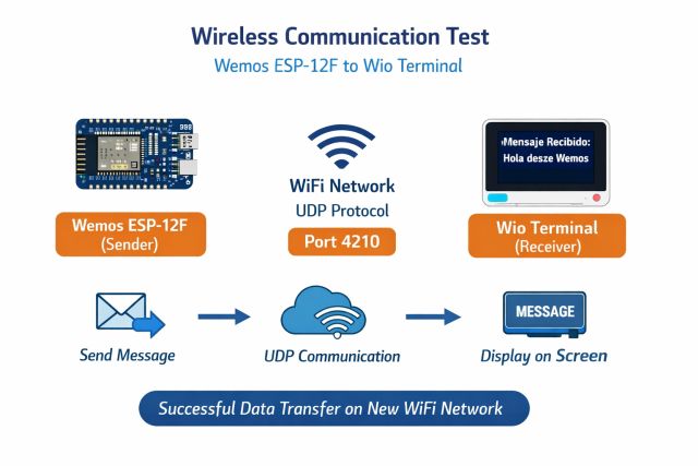
Having already established a wired local network using I2C and a wireless MQTT Publish-Subscribe connection during the group stage, I am now going to implement a local network via Wi-Fi. To do this, I will once again use the Wio Terminal D51R as the receiver and the Wemos D1 Mini as the transmitter. The idea is to send data packets through a local UDP architecture, where the transmitter sends messages directly to the receiver's IP address over a local Wi-Fi network, without any intermediaries.
This is a fundamental difference between the two data transmission architectures I am using:
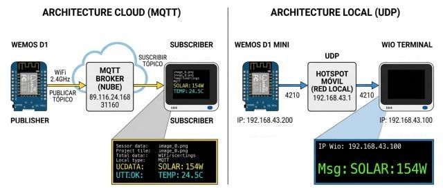
- Cloud Architecture (MQTT): The Wemos and the Wio communicate through an internet server. This is ideal for accessing data from anywhere in the world.
- Local Architecture (UDP): The Wemos and the Wio talk directly to each other "peer-to-peer" over the air, without intermediaries. This is ideal for speed, privacy, and total control within your own network.
The Key Difference:
- MQTT: You need a server (broker) to receive and distribute the messages.
- UDP: The Wemos sends the data packet directly to the Wio's IP address. If the Wio is "listening," it catches it. If not, the message is lost in the air—but that’s okay, because the next one will arrive in a few seconds. The Wemos continues to send messages at set intervals based on its programmed frequency.
Once I finished programming both units, I must admit I ran into a few issues:
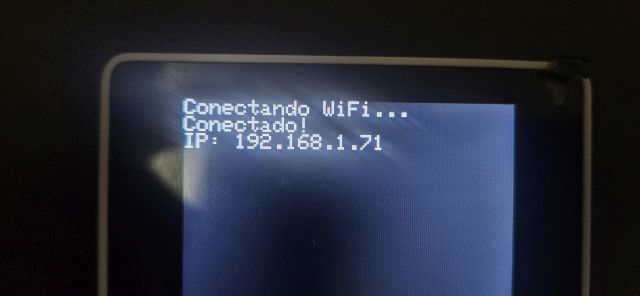
- The first step was to program the Wio as a receiver to set it to "listening" mode, while simultaneously having it provide its own IP address.
- Next, I programmed the Wemos as the transmitter, providing it with the Wio's IP address and setting the communication port to 4210, matching the Wio's configuration.
- Crucially, both devices must be connected to the same Wi-Fi network.
And this is where the problem appeared: the Wio wasn't receiving anything.
Aside from the typical issues—like not seeing what the Wemos was sending in the Serial Monitor because, in an oversight, I hadn't set it to the correct baud rate—the main problem was that the Wemos was transmitting correctly, but the Wio wasn't "hearing" anything.
After double-checking the entire code, I realized the problem wasn't there at all:
The issue was traced to network-level restrictions rather than software or hardware problems.
Both devices were initially connected to a guest WiFi network, which commonly includes security features such as:
- Client isolation
- Local traffic filtering
- Restricted device-to-device communication
The solution was to create a Wi-Fi hotspot with my mobile phone, which doesn't have as many restrictions.
The result was a total success: I was able to see the message sent by the Wemos perfectly on the Wio's screen. At the same time, I was able to verify on my phone that there was active data traffic between both devices.
BLUETOOTH CONNECTION - BLE Connection
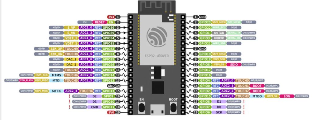
ESP32 WROVERTo establish a Bluetooth connection, I used an ESP32 Wrover, as the Wemos D1 I used previously does not have Bluetooth capabilities. The main features of this controller are:
| Feature | Wemos D1 Mini (ESP8266) | ESP32-WROVER |
|---|---|---|
| Wi-Fi | Yes | Yes |
| Bluetooth | ❌ No | ✅ Yes (Classic + BLE) |
| Cores | 1 (80/160 MHz) | 2 (Up to 240 MHz) |
| Extra RAM | No | Yes (PSRAM) |
| GPIO Pins | Few (9-11) | Many (approx. 22-25 available) |
Unlike other chips, the ESP32 features Dual Mode Bluetooth, which means it supports:
- Bluetooth Classic: The traditional standard (the one used for connecting speakers or transferring files). It is useful for applications requiring high data throughput.
- Bluetooth Low Energy (BLE): The modern standard for IoT. It consumes very little power and is used for connecting sensors to mobile apps or for allowing a device to "advertise" its presence without being permanently paired.
It also features:
- PSRAM: The "R" in WROVER stands for the inclusion of 4MB (or more) of external RAM (Pseudo-static RAM). This is vital if you are handling images, audio, or heavy network processes that the Wemos (ESP8266) simply couldn't handle.
- Dual-Core: It has two internal processors. You can assign one to manage Bluetooth/Wi-Fi while the other handles sensor readings or motor control, ensuring that nothing gets blocked or frozen.
TOOLCHAIN
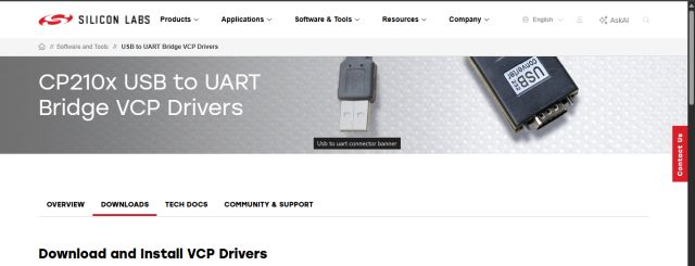
The first thing I needed for communicating with the ESP32-WROVER was, obviously, to connect it to my computer, and that's where the first issue arose. Although the USB-to-Serial CP2102 port was identified, it was necessary to install the VCP (Virtual COM Port) drivers from Silicon Labs to enable code uploading through the IDE.
The rest of the toolchain is the same one I explained at the beginning, and I encountered no further issues with it.
Once my Arduino IDE was prepared to work with both the ESP32-Wrover and the Wio Terminal, the next step was to develop the necessary code to send a message from the Wrover to the Wio and have it displayed on the Wio's screen.
Challenges arose quickly:
- First, as previously mentioned, I had to install the drivers to manage the Wrover
- Once both devices were up and running, nothing was appearing on the Wio's screen. Therefore, the priority was to ensure the Wrover was actually transmitting. To do this, I downloaded the nRF Connect app on my phone to detect the Wrover. The test was a success—the Wrover was right there!
- Multiple code revisions finally allowed the Wio to detect the Wrover:
- Type mismatches: Functions like setManufacturerData no longer accepted the C++ standard (std::string), requiring the Arduino String class instead
- Data Packaging: I had to create intermediate objects (BLEAdvertisementData) to wrap the information, a requirement that was missing from older tutorials
- "Dialect" Conflicts: I tried sending raw bytes, but the Wio Terminal and the ESP32 were speaking different "dialects":
- The Wrover would send a value, but the Wio received it as a memory pointer (uint8_t*). Attempting to read it as plain text caused the code to crash or display garbage data
- To bypass these compatibility issues, I implemented a creative workaround: encoding the data directly into the device name
- The Workaround: The ESP32 would dynamically rename itself as "W:1", "W:2", etc
- The Result: The Wio only had to read the device name—the most basic element of BLE—and extract the number. It finally worked!
- Final Hurdles: I eventually managed to get the Wrover's name to appear on the Wio's screen, but not without one last scare. The LCD screen had a very slow refresh rate; while the Wio was busy processing the display, the Wrover continued broadcasting. Consequently, even though the Wrover updated its name every second, the Wio was only catching about 1 out of every 40 messages
Conclusion: Wireless communication does not depend on the code alone; it relies on the correct environment configuration (drivers), the management of hardware latencies (screen vs. radio), and the ability to adapt to ever-changing library versions.
Regarding the screen refresh rate, I decided to leave it as is for this test. It was enough to prove the concept and verify that the data was being transmitted and parsed correctly.
Acknowledgments I must mention that all these code revisions were possible thanks to the invaluable assistance of Gemini (Google AI), as my current knowledge of Arduino programming is still in its early stages.
DIRECT WI-FI CONNECTION WITH A TEMPERATURE PROBE
To conclude, and having tested the most characteristic types of communication, we still need to test direct Wi-Fi communication without an intermediate network.
Unlike previous instances, here we create our own network infrastructure without depending on external routers:
Network Architecture: Access Point (AP) Mode
- ESP32-WROVER (Server/AP): Configured in Soft Access Point mode. It acts as the network's "router," assigning an IP address (192.168.4.1) and running a basic web server on port 80.
- Wio Terminal (Client/STA): Configured in Station mode, connecting to the Wi-Fi network generated by the ESP32 using credentials (SSID and Password).
In this way, I generate a Client–Server private network: the Wio sends a "GET" request (acting like a web browser) and the Wrover responds. The key feature is that this is an isolated network, establishing direct communication between the two components.
For the test execution, I connected a temperature probe to the Wrover's GPIO4. I used the same module from previous assignments, which already includes the built-in pull-up resistor required for the 1-Wire communication protocol.
Once connected, we can observe that in this case, the communication is nearly instantaneous, allowing the temperature value to be displayed on the Wio's screen immediately.
The conclusion, when comparing the two direct communication methods used (Bluetooth vs. Wi-Fi), is that:
| Feature | Bluetooth Low Energy (BLE) | Wi-Fi (AP Mode) |
|---|---|---|
| Reliability | High packet loss (in this setup). | Very high (TCP protocol with retries). |
| Ease of Use | Complex (profiles, UUIDs, advertising). | Simple (URL and text-based). |
| Speed | Slow update rate (due to scanning). | Nearly instantaneous (continuous flow). |
| Compatibility | Sensitive to library versions. | Universal (Web Standard). |
The use of a local Wi-Fi network eliminated the scanning latencies experienced with Bluetooth. The Access Point mode on the Wrover allows for the creation of an independent sensor ecosystem with immediate communication between devices.
AI Collaboration & Code Generation Insights
To obtain the Arduino code shared above, I collaborated with AI, specifically using Gemini. However, there is no single, specific prompt used to generate the code. Instead, the process relies on an ongoing, natural dialogue where I explain the logical ideas and specific tasks I want the microcontroller to execute.
Furthermore, with the memory and past activity features enabled, Gemini retains the context of previous project developments and adapts to my workflow preferences. As a result, the AI often anticipates my technical requirements, occasionally proposing relevant code structures even before they are explicitly requested.
CONCLUSION
Having seen and executed all these connections—and especially considering that I had never worked with networks at this level before—I can say that a world of possibilities has opened up for new projects. Given the vast variety of wired and wireless connections available, it is hard to imagine a project that wouldn't find a suitable fit.
At the same time, I am now aware that I have been wiring networks at work for many years—such as I2C and SPI (both in star configurations and daisy-chaining data lines), as well as UART connections. However, from my usual technical perspective, I was simply following manufacturer instructions. For instance, in technical documentation, we often see pins labeled as + and - instead of TX and RX.
Now, I can truly identify exactly what type of connections I am making.