Week3 Computer controlled cutting.
Group Assignment
link to the FabLab León group assignment
This week, the four students from FabLab León and FabLab Ponferrada worked together as a group. The task was to design something to cut on the laser cutter and then assemble it. The first step was to get to know the machine, its operation, and safety measures.
The safety measures for the laser cutter are detailed in the group documentation developed by my colleague Beni.
Safety MeasuresNext, we will discuss its operation, focusing specifically on the cutting process:
Like any tool, when cutting any type of material, some material is always lost. This means that when setting the dimensions and measurements in our design, we have to compensate for this material loss. To do this, we need to increase the dimensions of solid areas and reduce the dimensions of any holes we make. By how much? To determine this, we must perform a Kerf Test:
KERF TEST
The first step was to create a basic design of a 10 mm × 10 mm square:
A simple solid square was edited using RDWorks software and sent directly to the laser machine for production.
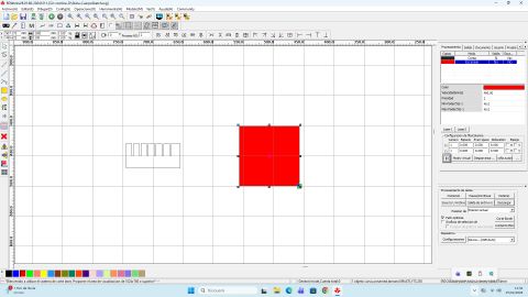
To make this piece, we used 2 mm thick wood as material, so we set the laser configuration to 60% power and a cutting speed of 200 mm/s
The result is as follows, where we measured the actual side length:
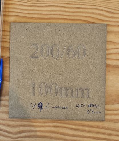
Once the material was cut, we used a digital caliper to measure its actual dimensions.
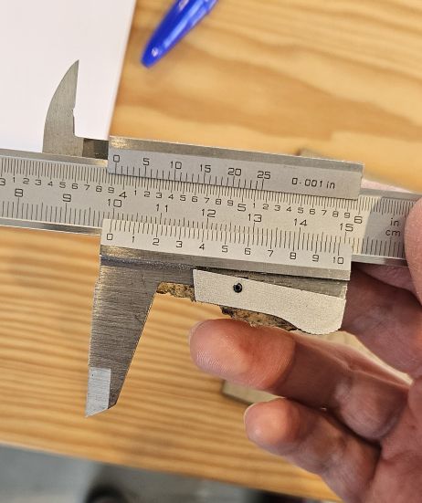
The measurement result, as shown on the caliper, is 99.8 mm, although in the photo there was a mistake in writing the measurement due to the excitement of the moment. That is, we lost 0.2 mm of material, 0.1 mm on each side of the square, so THE KERF is 0.1 mm.
Individual Assignment Part 1
The individual assignment for this week consists of designing a project for the laser cutter using parametric design. For this, I chose to work in FreeCAD, which I had already used for last week’s assignment.
On this occasion, I designed a lamp. Initially, it was going to be a pencil holder, but as I progressed with the design and faced the multiple challenges FreeCAD presented, I changed my idea and created this design. After adding the light fixture, it will become a desk lamp:
Comb and Design
Working in FreeCAD is honestly complex until you understand the program. At first, it seems easy, but the main difficulty lies in constraints.
Working in parametric design means that all important dimensions of the design must be referenced to a table (like Excel), so that later you can change the dimension values and the design automatically adjusts to the new dimensions without altering the rest of the structure. For this, there are constraint types such as perpendicularity, symmetry, or parallelism, which, once applied to the corresponding sketches, remain active even if the design dimensions change.
Before starting the design, it is necessary to know the width of the slots that will allow the pieces to fit together without coming apart. For this, I need to know the press-fit of the material I am using, which is 2.5 mm thick cardboard. Intuitively, one might think the slot width should be 2.5 mm, but it is important to remember that the joints must hold without any glue. Therefore, they need to be tight enough to stay together, but not so tight that the material breaks.
COMB
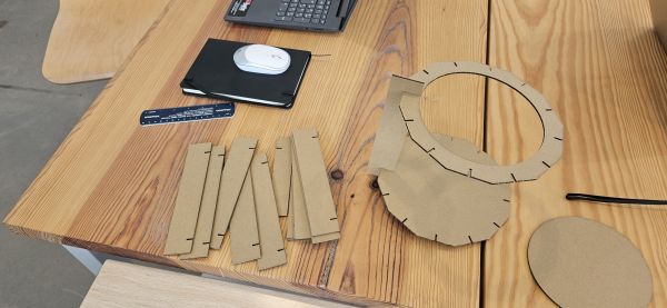
What I need to design first is a comb with slots of different widths. Starting from the theoretical material thickness of 2.5 mm, we create other slots with larger and smaller widths, which will then be used for real tests of the joint tightness.
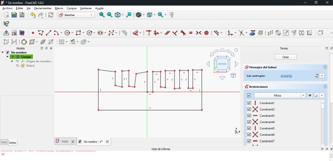
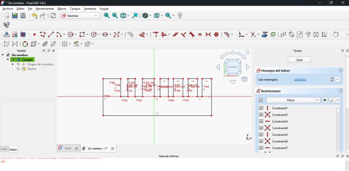
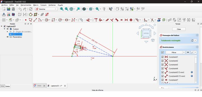
Next, we see how I designed the comb, first using the polyline tool and then applying the appropriate constraints and dimensions for the slots, referencing them in the corresponding table:
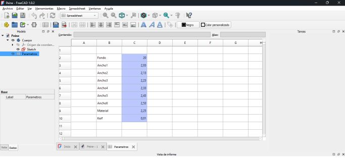
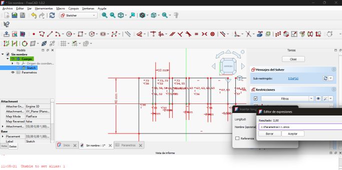
Here we can see the Kerf calculated during the group task, subtracted from the real value multiplied by two, to compensate for the material lost on each side of the slots.
We can observe that I deliberately changed the material thickness to 2.25 mm. This was done to manufacture a smaller comb and to achieve tighter joints.
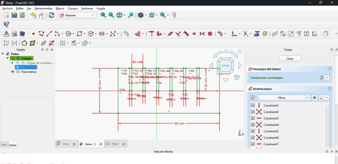
Design process of the laser-cut test comb
Once the comb was finished and after performing the corresponding tests, I decided to use a slot width of 2.13 mm, as I intended the joints to be tight.
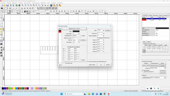
Cutting parameters and final result
DESIGN
Once we know the press-fit needed for the joints, we can proceed with the final design.
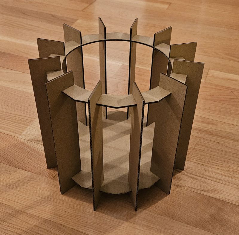
The initial concept is simple: we choose a dodecagon as the base, and on each face, we make a 1 cm deep slot. Then we create twelve beams with two slots each, and finally a top crown made from a dodecagon similar to the base, but with a hole in its center.
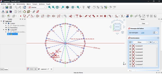
The initial idea was simple, but when I tried to create the dodecagon with the slots on each face, fully parametrized, problems arose.
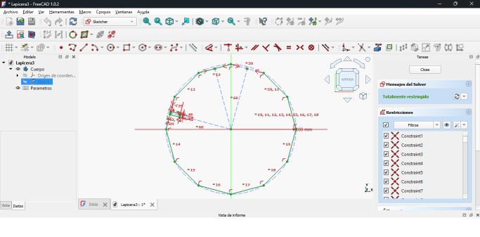
Initially, I made the dodecagon with the corresponding tool, and for the slots, I first thought of using perpendicular constraints. However, the slots need to be centered on each face, so I tried symmetry constraints. Initially, this seemed to work, but then I had to fix the slot to the radius. Otherwise, when changing the radius parameter, the slot stayed in the same place or the shape collapsed. I chose to anchor the bottom of the slot to a construction line from the center to the midpoint of the side. This solved most problems—until I needed to open a hole in the side for the slot. Now there was no midpoint of the side! The next step was to draw a construction line in the opened hole and reapply constraints of parallelism, equality, perpendicularity, and symmetry, and re-anchor the figure to the new construction line extending from the center to the center of the new line.
Up to this point, there were many headaches, but I learned how to use constraints, construction lines, and how to link dimensions to the parameter table.
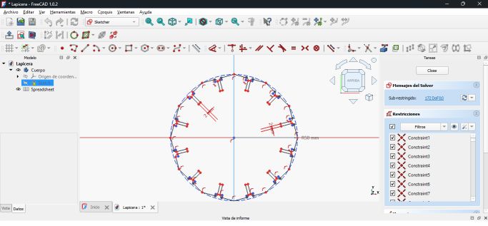
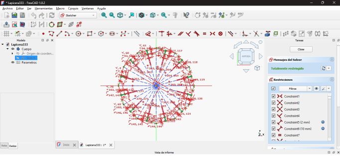
Designing a single edge of the dodecagon
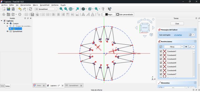
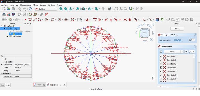
The biggest challenge came next. “I’m not going to do all this for each of the twelve faces,” I thought. While researching, I discovered the polar tool, which allows replicating the slot on each of the twelve faces. It worked, but this tool does not copy constraints. It applies an angular constraint relative to the original figure, but does not copy the original constraints. Total chaos! The figure would collapse when changing any parameter. Solving this took hours of videos, trials with AI, and many tests in FreeCAD.
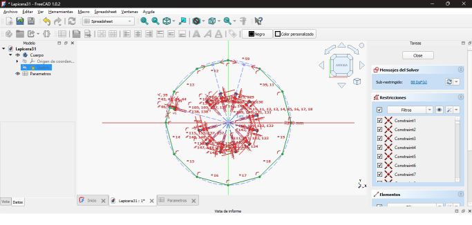
The solution came one Sunday morning, hours before going to the FabLab to cut what I didn’t have ready. Once one face was fully constrained, I deleted the rest of the dodecagon, leaving only the face, the slot in question, and a construction line acting as the dodecahedron radius. A constraint to the coordinate axis and a radius dimension on the construction line. Then I used the polar tool—and it worked! Some extra constraints appeared, which had to be deleted, but the result was as expected.
It was quite a learning curve, and I’m still getting the hang of it.
What I learned from this is that in FreeCAD, it is not advisable to draw over previously drawn sketches. Also, it is very important to always anchor everything to a common point; otherwise, problems will always occur.
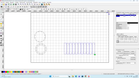
CUT
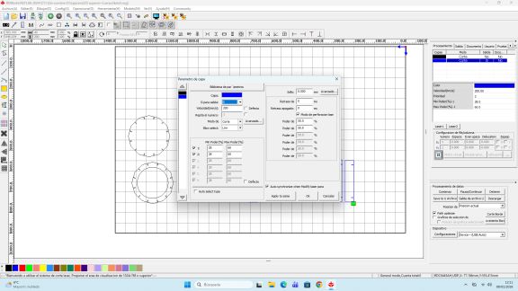
Once the design was completed, we moved on to cutting it using the laser cutter. To do this, the first step was to export the 2D design from FreeCAD to a vector file in .svg format, which is compatible with the software of our laser cutting machine. We then adjusted the cutting parameters and transferred the design to the machine.
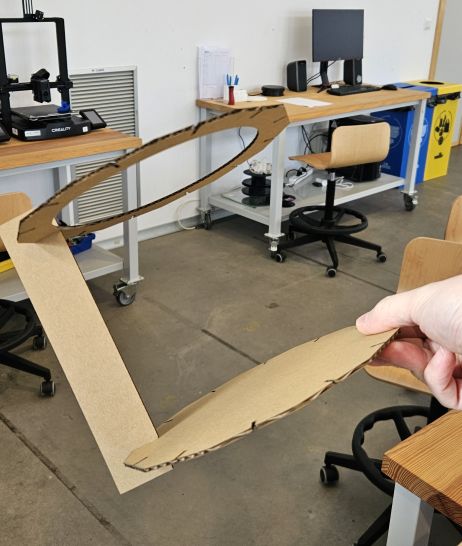
At the machine, we placed the material to be cut, adjusted the focal distance to 7 mm from the laser to the surface of the material, set the origin, and checked that the design fit correctly on the material by running several frame tests. After verifying all safety measures, we closed the lid, turned on the extraction system, and started the cutting process.
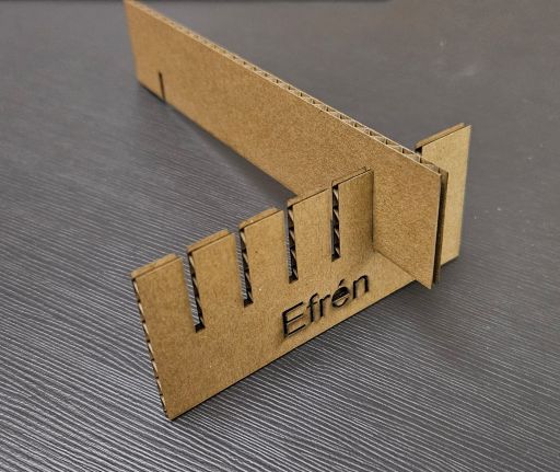
Once all the pieces were ready, the only thing left to do was assemble them and… I had my first creation in the Fab Academy!
Individual Assignment Part 2
Vinyl cutter
To finish this assignment, I had to make a sticker using the vinyl cutter. Although it is a much simpler machine than the laser cutter, it also has its own procedures that must be followed.
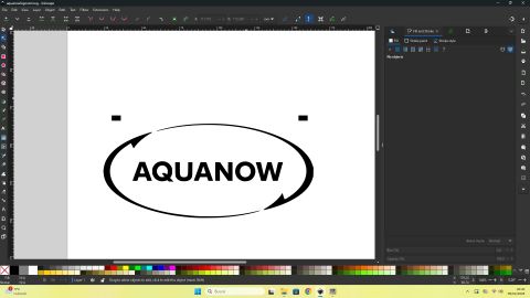
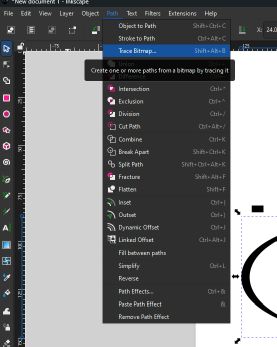
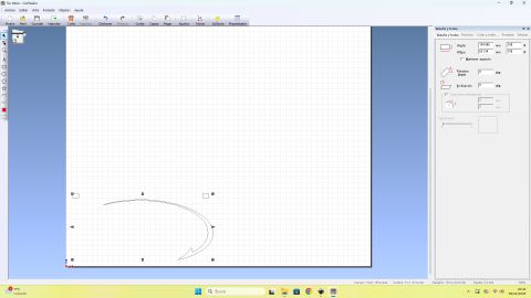
As always, the first step is to create a design. In this case, I decided to design what could be the logo of my final project. The design was created as a vector graphic using Inkscape and then transferred to the vinyl cutter computer. Once the design was loaded, and taking into account that it consists of three different colors, the steps to follow were the following:
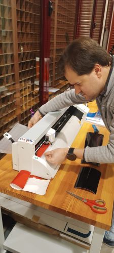
• We place the material in the vinyl cutter, securing it with the rollers after adjusting them to the width of the material.
• We select roll or sheet depending on whether we are using a roll of material or leftover pieces.
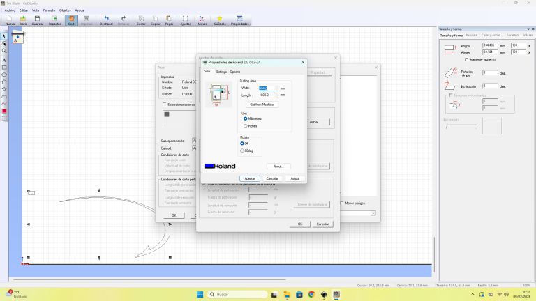
• We let the machine measure the material, and then import those measurements into the computer software to correctly adjust the design.
• We adjust the blade depth and set the origin.
• Once everything is ready, we start the cutting process.
The particularity in this case is that the design must be divided into three different parts, one for each color, repeating the previous steps for each one.
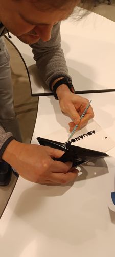
Finally, we obtain three stickers of different colors, each one corresponding to a section of the design. At this point, the “manual” part begins. We remove the excess material from each sticker, and using transfer tape, we collect the three colors and assemble them together into a single piece, recreating the original design.
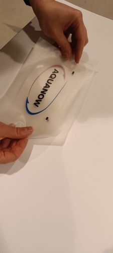
The key trick for this last step is that we drew two reference marks in the design, common to all three parts. This provides a guide to correctly align the different layers on the transfer tape.
And now, we have the final sticker!