Week 3
Computer-Controlled Cutting
Assignment documentation
Contents
Week questions/tasks
Starting Point
At the starting point of this assignment, I had previously seen vinyl cutting and laser cutting being used, but I had never operated either machine myself. I was familiar with the concepts at a very basic level, but lacked hands-on experience with the complete workflow.
Regarding parametric design, I had no prior experience at all and was not aware that this type of design approach was possible. This assignment therefore represented a completely new way of thinking about design, introducing me to the idea of creating models that can adapt automatically through parameters and constraints.
Group assignment
As part of the group assignment, I completed the lab safety training and collaborated in the characterization of our laser cutter, analyzing parameters such as focus, power, speed, cutting rate, kerf, joint clearance, and different joint types.
My part consisted of documenting the specifications, operation, and safety. The full process, tests, and results are documented on the group work page (linking to each one's individual pages parts). In any case, I have compiled all the characteristics of the laser cutter on this specific page: Framun Nova Elite 14s Page.
Group Page: FabLab León 2026 Group Page
Specific characterization of: Framun Nova Elite 14S - Beni's documentation
About safety in the Lab and me using digital cutting machines
During the lab safety training, I learned the importance of following clear procedures when using digital cutting machines, such as the laser cutter and the vinyl cutting plotter.
Before starting any job, I checked that the material was suitable for each machine and that the work area was clean and properly set up. For the laser cutter, I verified the focus and ventilation and made sure not to use unknown or hazardous materials.
While using the laser cutter, I always kept the machine under supervision, never leaving it unattended, and with the lid closed to avoid direct exposure to the laser. When using the vinyl cutter, I paid special attention to the correct placement of the material and to adjusting the cutting pressure properly, in order to avoid damaging the blade or the cutting surface.
After finishing, I waited for the machines to stop completely before removing the material and cleaned the work area. This experience reinforced the idea that lab safety depends not only on the machines, but also on the constant attention of the operator.
Individual assignment
Vinylcutter
1 Vinyl design
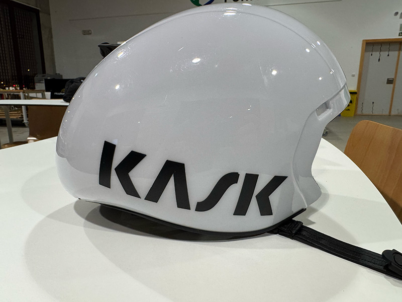
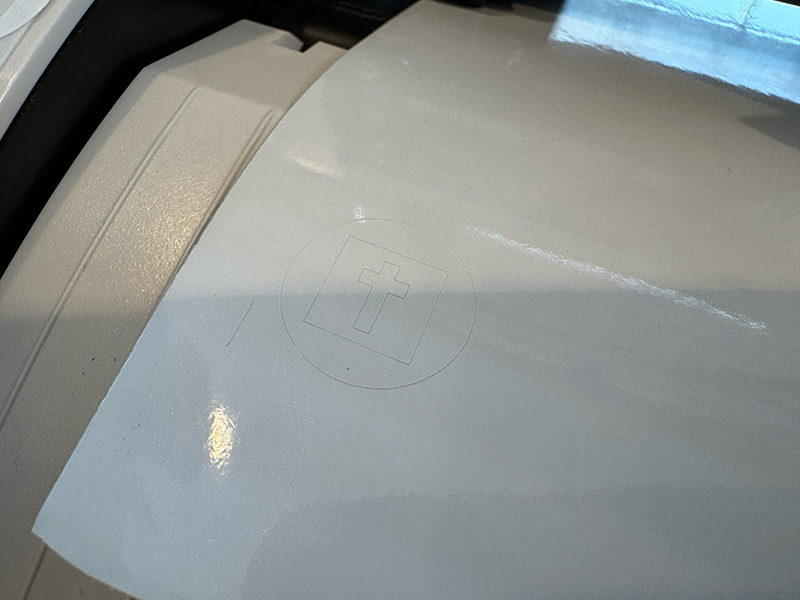
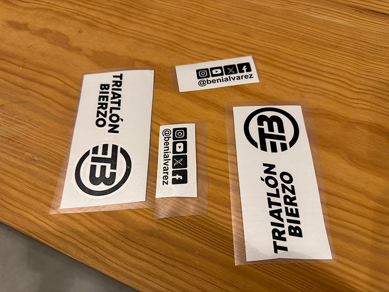
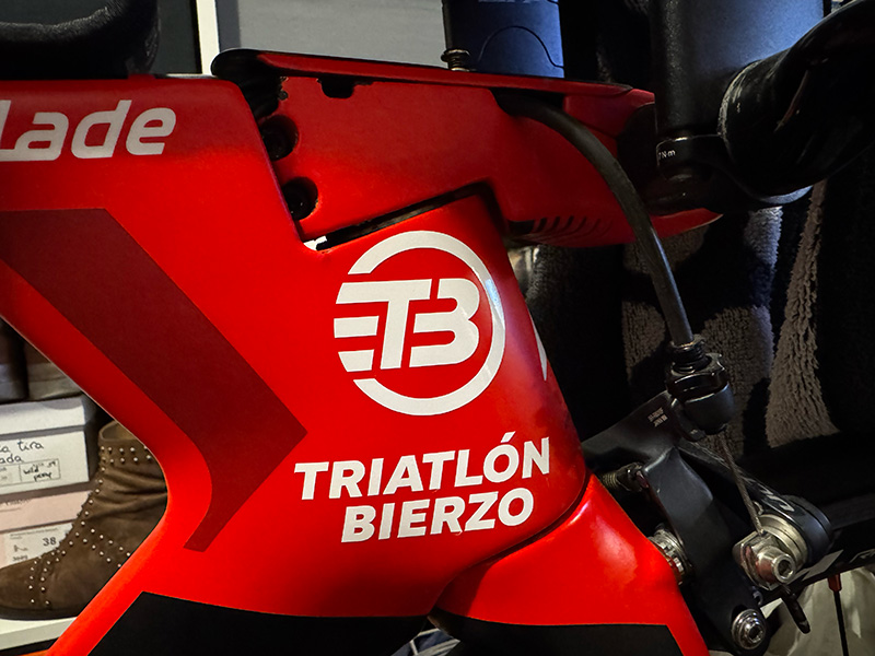
The goal of this exercise was to customize my triathlon racing helmet, replacing the original manufacturer decals with a custom design. To do this, I first removed the stock vinyls and then designed new ones including the logo of my triathlon club, additional logos, and my social media username.
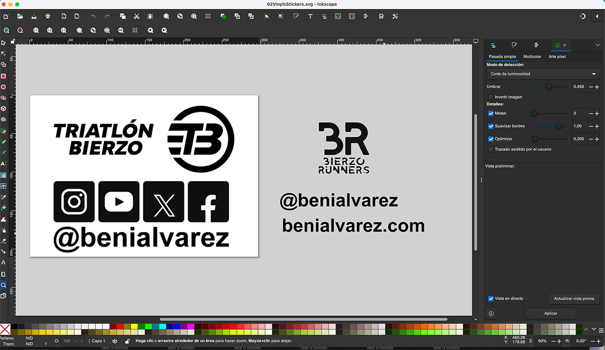
I created the design using Inkscape, working exclusively with vector graphics and using a single color suitable for vinyl cutting. During the design process, I avoided very small details and paid attention to line thickness to ensure a clean cut and proper application on a curved surface like a helmet. The final file was exported in .svg format
2 File preparation for the vinyl cutter
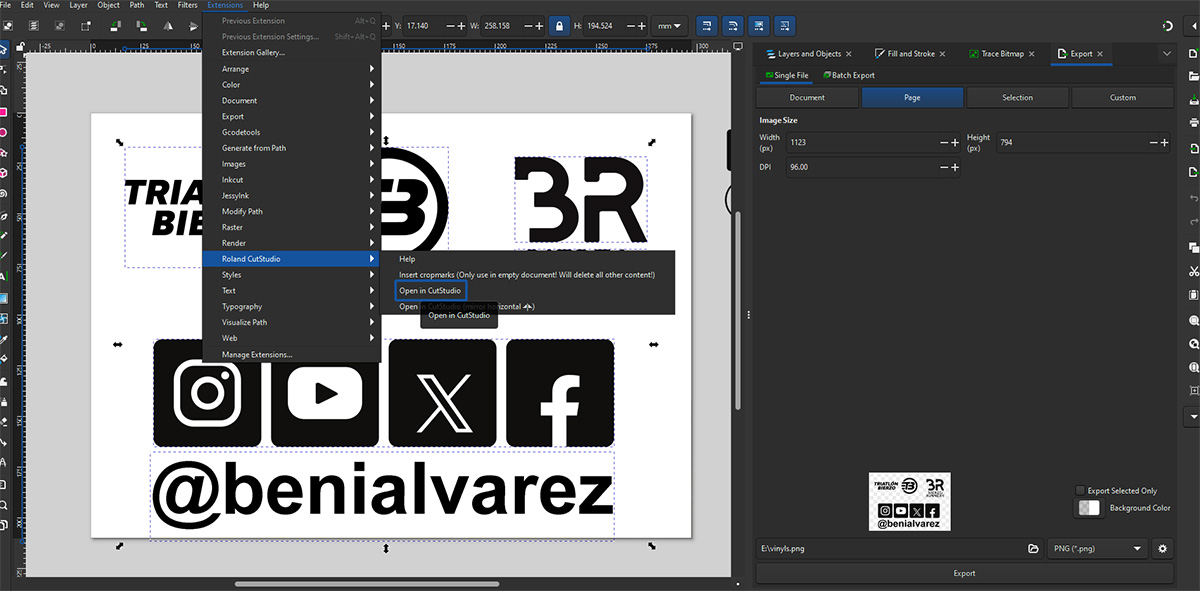
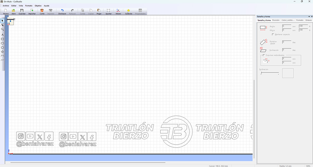
Once the design was finished, I prepared the file for vinyl cutting. From Inkscape, I selected the elements to be cut and sent them directly to Roland Cut Studio using an integrated extension, which allowed me to preserve the original scale and proportions of the design.
In Roland Cut Studio, I adjusted the final sizes and placement of each element, taking into account the geometry of the helmet and the final position of the logos and text. This step ensured that the file was ready to be sent to the vinyl cutter.
You can download the original file from the downloads section at the bottom of the page.
3 Vinyl cutter setup
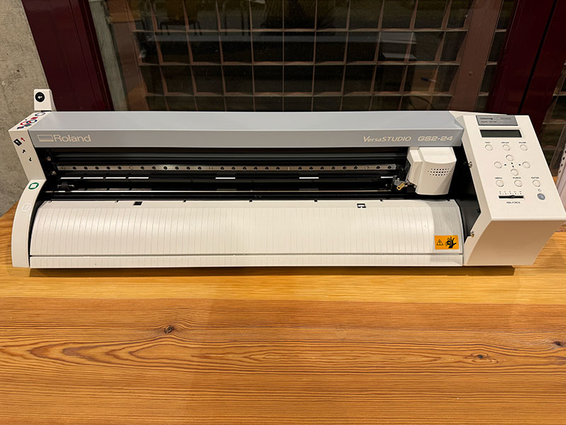
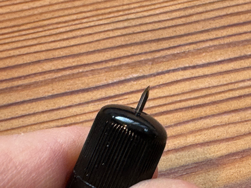
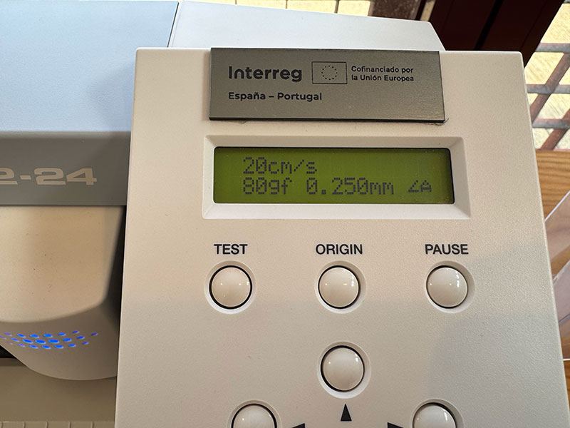
I performed the cutting using a Roland GS2-24 vinyl cutter with 45º cutting blade and loading a roll of black adhesive vinyl (I also used the white vinyl for other stickers). Before running the final job, I configured the cutting parameters suitable for this material, using a cutting force of 80 gf, which was enough to cut the vinyl cleanly without damaging the backing layer. Speed: 20cm/s. Blade displacement: 0.2500mm.
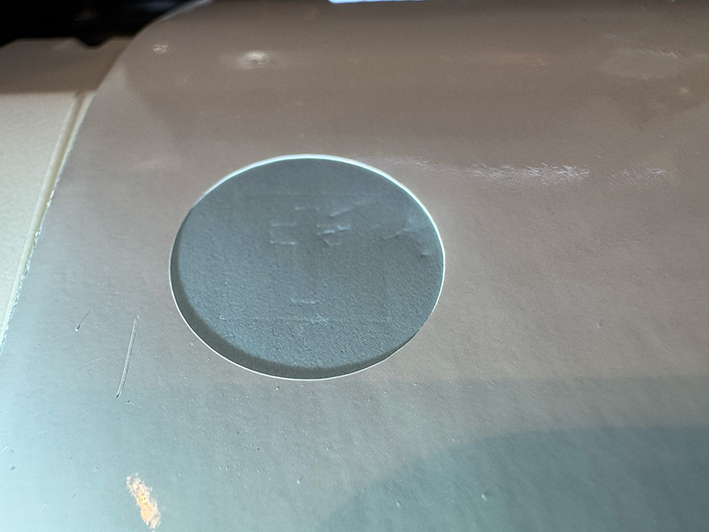
Before cutting the final design, I ran the built-in cutter test, which cuts small circles and a cross. This test allowed me to verify that the selected pressure was correct and helped ensure an easy weeding process afterward.
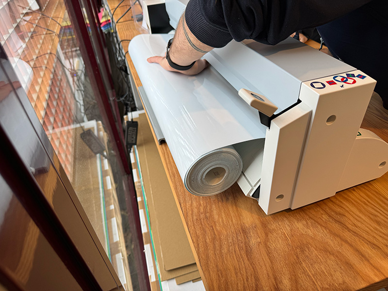
4 Cutting process
With the vinyl properly loaded and the file prepared in Roland Cut Studio, I started the cutting process. During the operation, the vinyl remained well aligned and the cut was precise and consistent.
Once the cutting was finished, I visually checked that all elements were correctly cut, paying special attention to the text and finer details before removing the vinyl from the machine.
High quality video available on my YouTube channel ↗️.
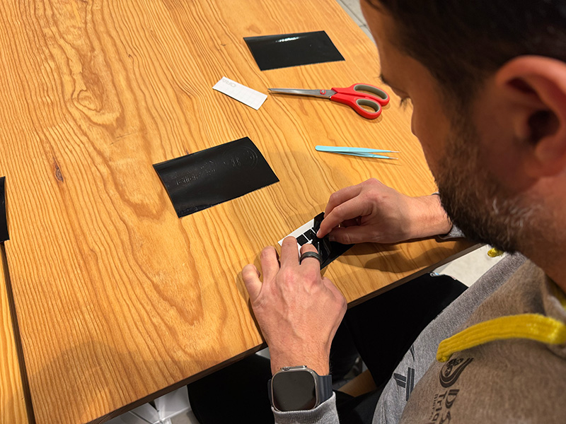
5 Weeding the vinyl
After cutting, I proceeded with the weeding process, manually removing the excess vinyl and leaving only the final design elements. I carried out this step carefully, especially around small details, ensuring that no part of the design lifted from the backing.
A properly adjusted cutting force made this step much easier, as the vinyl separated cleanly without tearing or deforming the design.
6 Applying the transfer tape and final application on the helmet
Once the vinyl was fully weeded, I applied a transparent transfer tape over the design. Using a transparent transfer allowed me to clearly see the position of all elements during the final application. I applied even pressure to ensure that all vinyl elements adhered properly to the transfer.
After that, I removed the original vinyl backing, leaving the entire design attached to the transfer tape and ready to be applied to the helmet.
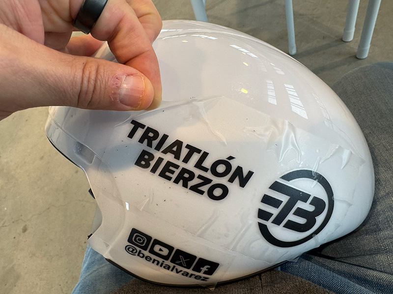
I applied the vinyl directly onto the triathlon helmet, which has a curved surface. I carefully positioned the vinyl and pressed it from the center outward to avoid air bubbles.
Once the vinyl was properly adhered, I slowly removed the transparent transfer tape, making sure that all elements stayed in place and aligned according to the original design.
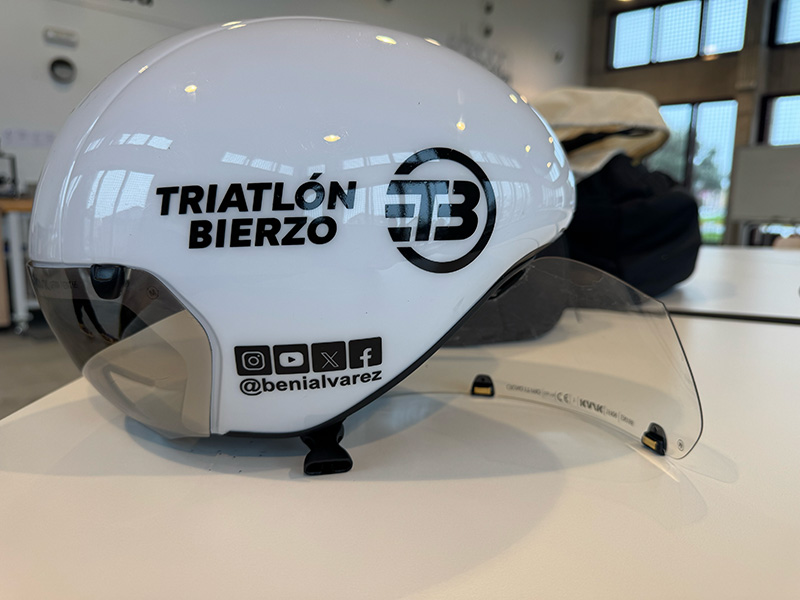
Result and reflection
The final result was a fully customized helmet with a clean and professional finish, suitable for competition use. In addition to the helmet, I also produced additional white vinyl decals to personalize my bike, following the same workflow and cutting process described above. This helped reinforce the repeatability of the method across different applications and materials.
This exercise allowed me to understand the complete adhesive vinyl cutting workflow, from vector design to final application on real objects. The main takeaway was the importance of performing test cuts and adapting the design to the surface where it will be applied, especially when working with curved or non-flat geometries.
For future work, I would like to experiment with different vinyl types and colors, as well as further refine the cutting parameters to achieve better results on more detailed designs or different surfaces.
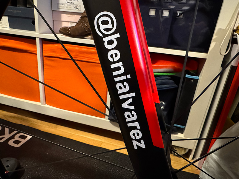
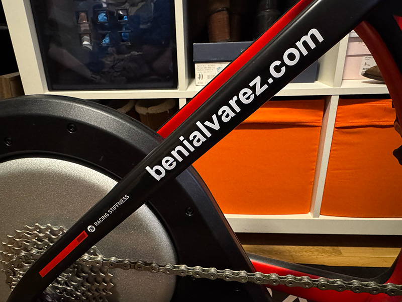
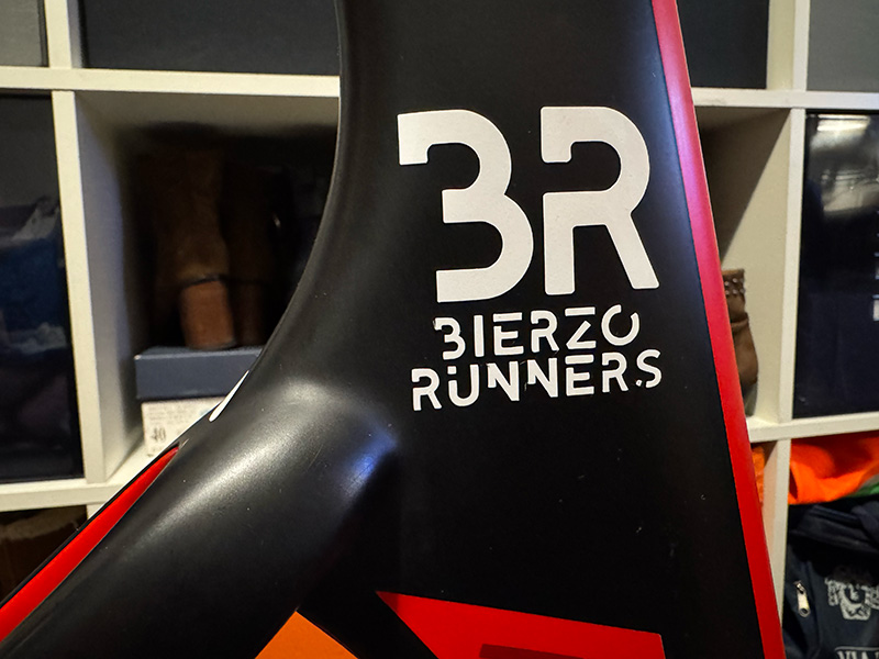
Extra. Customization of my triathlon bike
In addition to the helmet customization, I also produced white vinyl stickers to customizace my bike, including clubs logos I belong to, my personal website, and my social media username. These decals were designed and cut following the same workflow, which allowed me to easily adapt the process to different elements while maintaining a consistent visual identity across my equipment.
Parametric design. Measurement comb
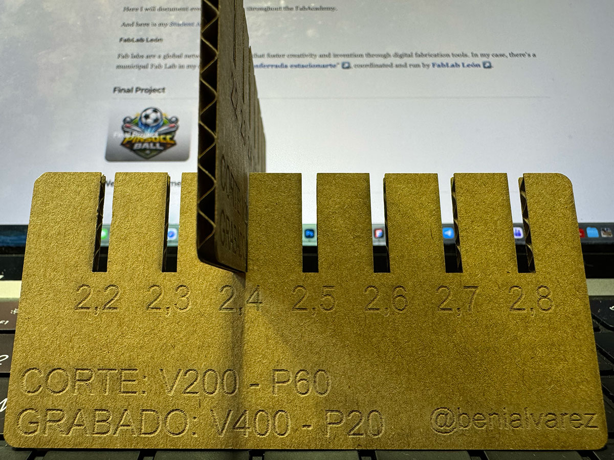
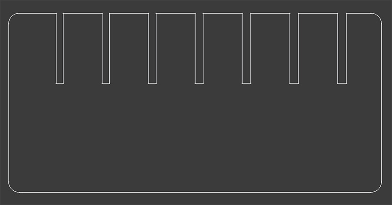
I designed this measurement comb as a calibration tool for press-fit joints using a parametric design approach. The material used was 2.50 mm cardboard, and the main goal was to compensate for the real laser cutting kerf, which in this case was 0.1 mm.
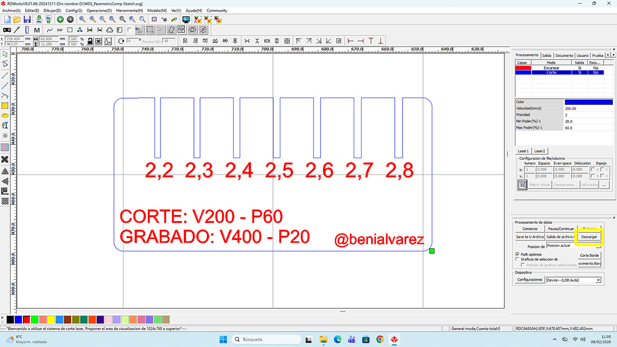
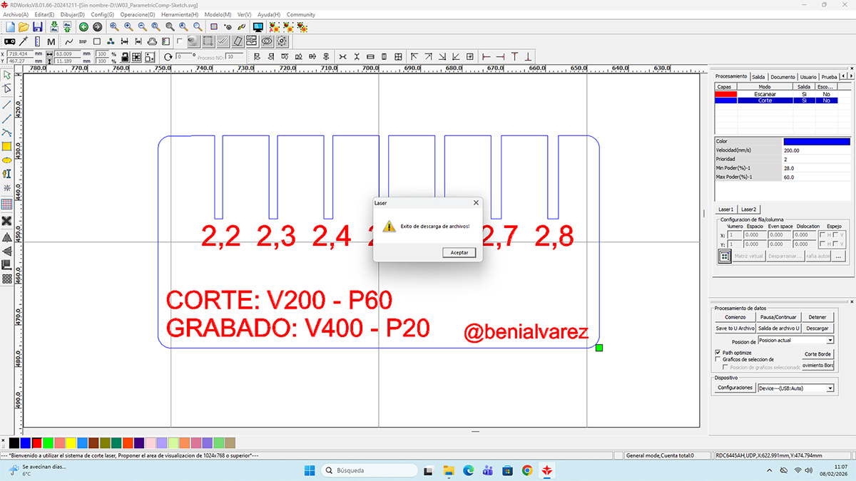
The design starts from the nominal material thickness and automatically generates a series of slots with progressive increments, ranging from 2.2 mm to 2.8 mm, allowing me to directly test which width provides the best fit. Thanks to the parametric setup, any change in material thickness or kerf value can be applied instantly without redesigning the entire part.
Each slot is engraved with its corresponding value, making it easy to visually identify the optimal fit. This turns the comb into a fast, repeatable tool for adjusting tolerances and validating press-fit joints before producing final parts.
Reference values
| Parameter | Value |
|---|---|
| Material | Corrugated cardboard 2.5 mm |
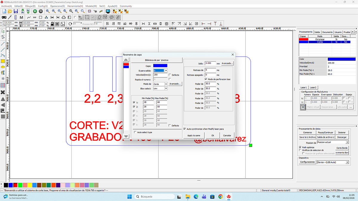
| Vector (Corte) | Speed: 200 || Power: 60 |
| Raster (Grabado) | Velocity: 400 || Power: 20 |
Parametric design
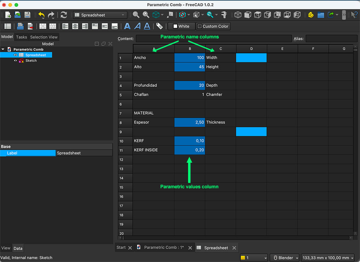
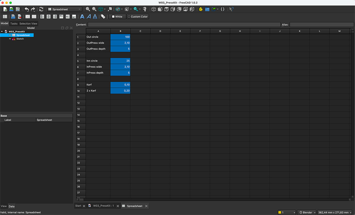
I started by creating a Spreadsheet in FreeCAD where I centralized the main parametric variables of the design. This allows me to control and modify the entire model from a single place.
In the Spreadsheet, I defined a variable for the real cardboard thickness, set to 2.50 mm, which I use as the base reference for sizing the slots.
I added a variable for the laser cutting kerf, set to 0.1 mm, and an additional variable for the double kerf, which I use to compensate for the material removed on both sides of the cut.
I also defined independent variables for the total width and total height of the comb, allowing me to adjust the overall size of the part without affecting the internal design logic.
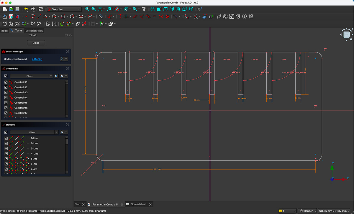
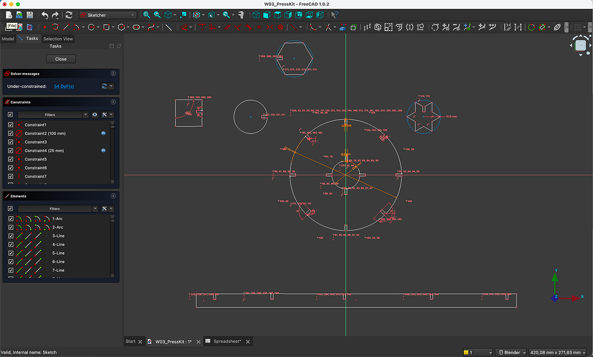
Once we have the parameters established, we proceed to draw the comb, applying restrictions to the strokes and angles, and then applying the dimensions linked to the parameters.
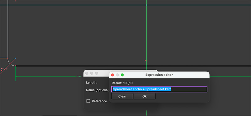
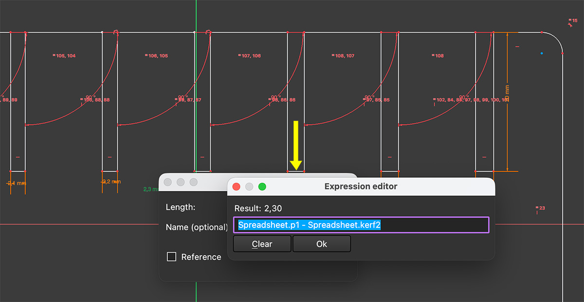
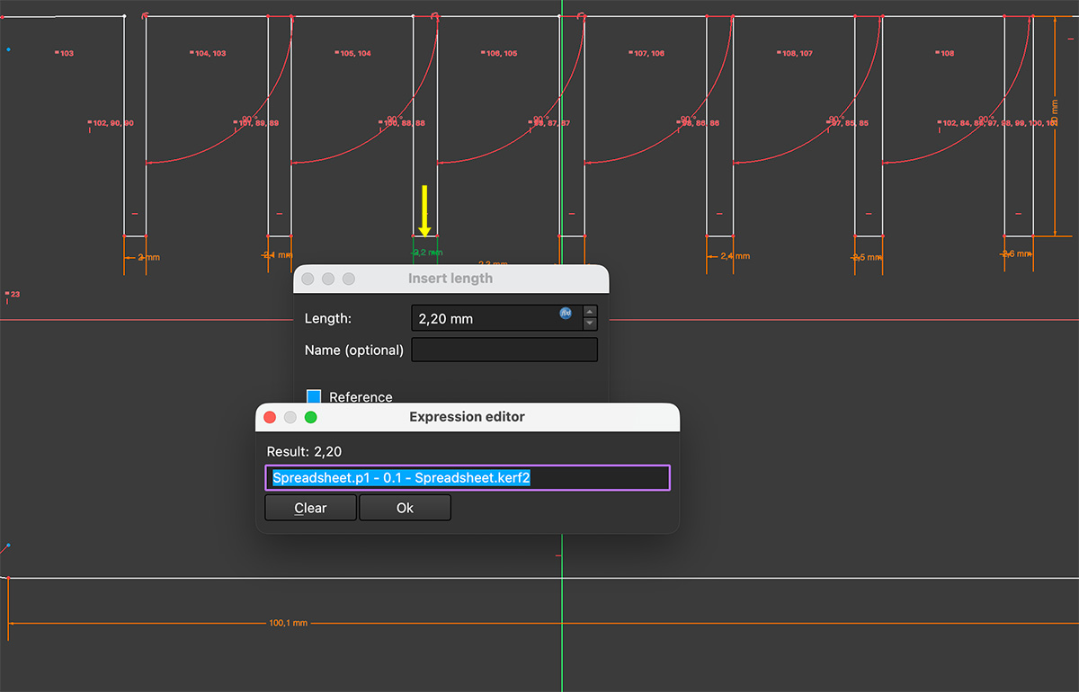
When defining the contraint distances, instead of defining each dimension independently, I used expressions directly in the design constraints, adding or subtracting progressive values to the thickness, kerf, and double kerf variables. For the central slot, I applied the material thickness value minus the kerf on each side, using the “Kerf inside (kerf2)” parameter (Kerf value x 2).
Each of the remaining slots was dimensioned by applying successive increments of +0.1 mm or −0.1 mm to the base value, allowing me to evaluate different press-fit adjustments without defining each width as an independent variable.
The constraints are therefore linked to expressions dependent on the Spreadsheet variables, so any change to the material thickness, the kerf, or the overall dimensions automatically updates the entire model.
You can download the original file from the downloads section at the bottom of the page.
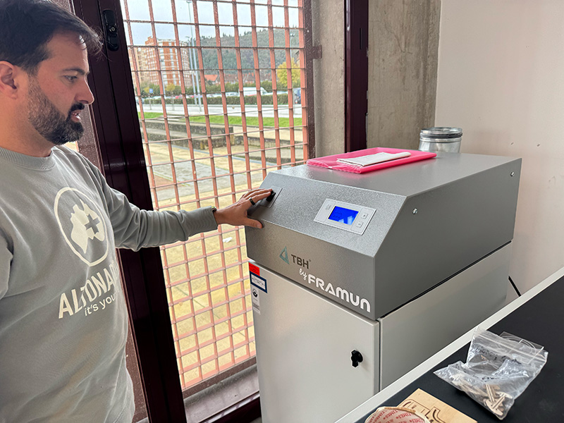
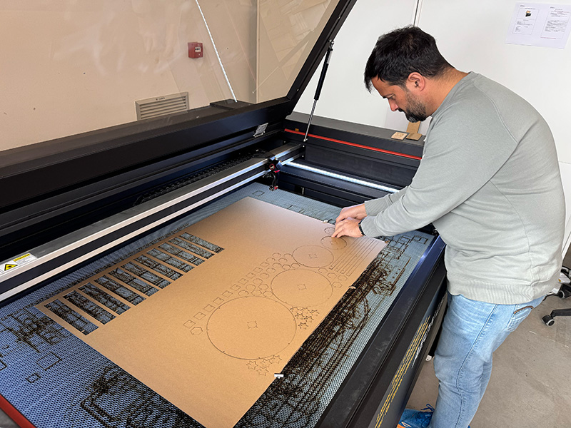
Production step using the laser cutter
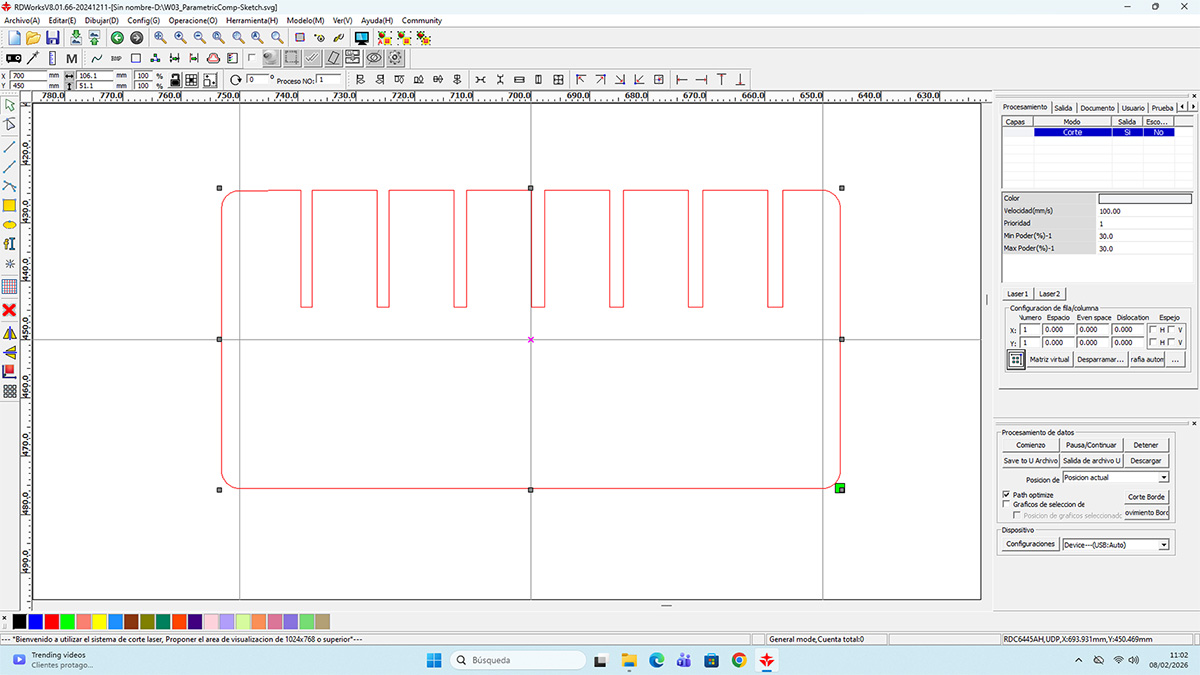
Once the parametric design of the comb was completed in FreeCAD, I prepared the file for fabrication using the laser cutter. Initially, I exported the model to .svg format to import it into RdWorks
Once the file was prepared in RdWorks, I added the engraved texts directly in this software, as they were not part of the original FreeCAD design. This allowed me to clearly separate Vector operations (cutting blue layer) from Raster operations (engraving red layer), assigning specific power and speed settings to each one.
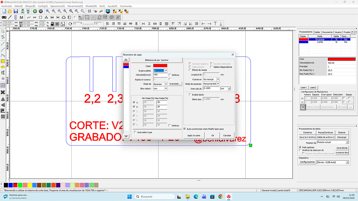
Before starting the job, I prepared the machine by setting the origin on the working bed, adjusting the material height to ensure proper laser focus, and checking that the extraction system was working correctly. Finally, I sent the job to the laser cutter by USB by clicking the download button in RdWorks, giving the file a name and supervised the entire process to ensure correct Vector cutting and Raster engraving.

Press-fit construction kit
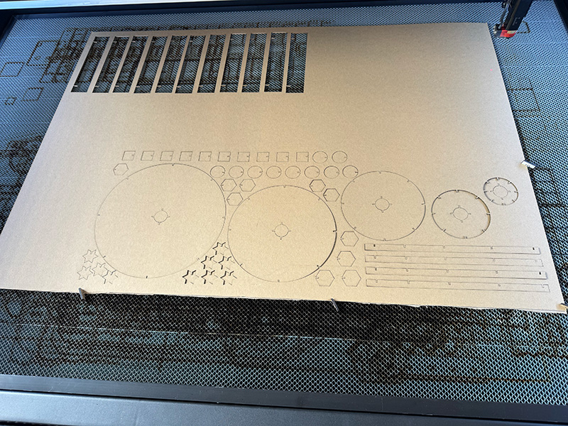
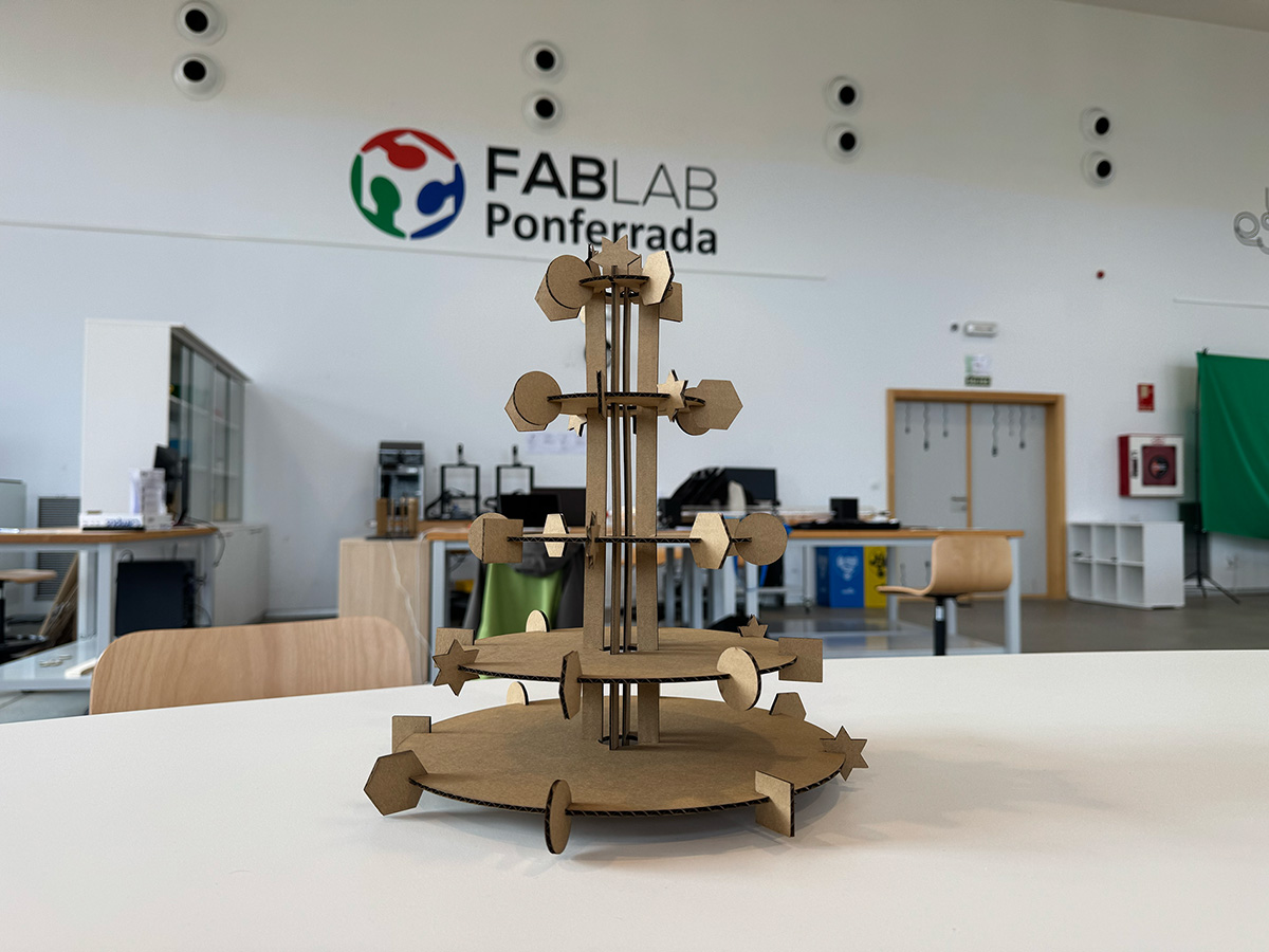
Once I had defined and validated the parametric design and the laser cutting workflow described in the previous sections, I applied the same approach to develop a press-fit kit in the shape of a Christmas tree, using cardboard as the material and a joint system without adhesives.
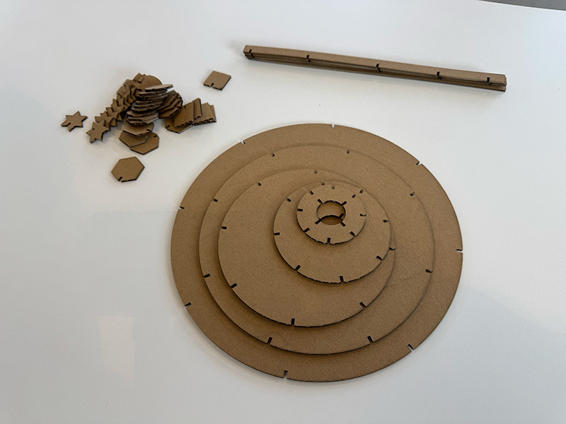
I created the design in FreeCAD starting from a single parametric model. From this base design, I adjusted the parameters to generate the different parts that make up the tree, varying the outer diameter of the rings to 60, 100, 150, 200, and 250 mm, corresponding to the different levels. Thanks to the parametric approach, all parts maintain the same fitting logic and proportions, automatically adapting to each size.
In addition to the main rings, I designed four decorative elements intended to be inserted into the different levels of the tree, as well as four internal parts that I designed to connect the rings together and act as a structural base, allowing the whole assembly to remain stable in a vertical position.
Reference values
| Parameter | Value |
|---|---|
| Material | Corrugated cardboard 2.5 mm |
| PressKit value | 2,3 mm (2,1 in design + kerf) |
| Vector (Corte) | Speed: 200 || Power: 60 |
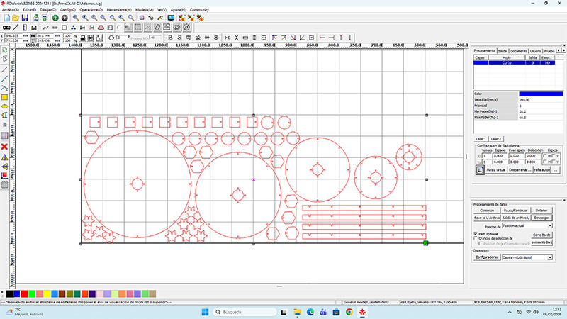
Once the final dimensions were defined, I exported the different parts from FreeCAD to .svg format, adjusting the parameters in each case to obtain the required sizes. I then imported all the files into RdWorks, where I arranged the parts on the working area and added the necessary repetitions for those parts that required more than one unit.
I configured the entire job as Vector, since this press-fit kit does not include any engraving operations.
For fabrication, I followed the same basic laser cutter preparation process described earlier: I set the origin on the working bed, adjusted the laser focus according to the material thickness, and checked that the extraction system was working properly.
High quality video available on my YouTube channel ↗️.
Finally, I assembled all the parts using only press-fit joints, checking that the fits worked correctly and that the resulting structure was stable without the need for screws or adhesives.
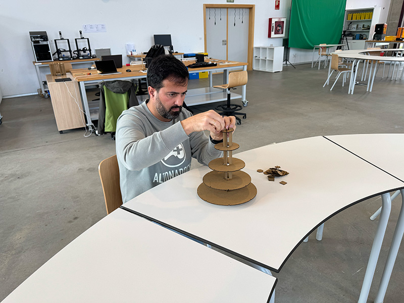
This process allowed me to validate the parametric design and confirm the effectiveness of laser cutting for manufacturing modular press-fit systems.
High quality video available on my YouTube channel ↗️.
Original design files for this documentation
Files for download
- Vinyls Stickers design (.SVG) SVG · 73 Kb
- Parametric Comb design (.FCStd) FCStd · 10 Kb
- Complete comb design in RdWorks (.rld) RLD · 670 Kb
- Parametric Press-fit Kit (.FCStd) FCStd · 50 Kb
- Parametric Press-fit Kit .svg individual parts (.svg) SVG · 12 Kb
- Complete Press-fit Kit design in RdWorks (.rld) RLD · 623 Kb
Credits
I would like to thank the instructors Nuria ↗️, Pablo ↗️, and Adrián ↗️ for their guidance and support throughout this assignment.
Also thanks to Javier ↗️ (FabLab Ponferrada Manager) for facilitating our access to the fablab and training us in the use of the machines.
I am also grateful to my FabAcademy’26 León group mates — Efrén ↗️, Íñigo ↗️, and Óscar ↗️ — for sharing knowledge, ideas, and troubleshooting together, making the learning process more collaborative and enriching.
The social media logos/icons were downloaded from:Vecteezy ↗️
All texts were written in Spanish and translated into English using Google Translate and ChatGPT.