Framun Laser · NOVA ELITE 14
Laser cutting — Operation & Safety
Base of this documentation by: Javier Bayón FabLab Ponferrada ↗️
Machine specifications
| Parameter | Value |
|---|---|
| Working area | 1400 × 900 mm |
| Laser power | 130 W |
| Laser tube | Glass CO₂ tube |
| Max cutting thickness | 0–30 mm (depending on material) |
| Software | RDWorks |
Cutting thickness and parameters always depend on the material and must be tested beforehand.
Compatible materials
- PMMA (acrylic)
- Wood
- Cardboard
- Polypropylene (PP)
- EVA foam
- Rubber for stamps
- Anodized aluminium (engraving only)
Machine operation
Power on and homing
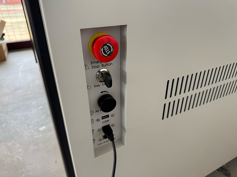
- Unlock the emergency stop by turning the red knob clockwise.
- The machine performs an automatic homing sequence, moving the head to the upper-right corner.
- Wait until the process finishes and the head returns to the last saved origin.
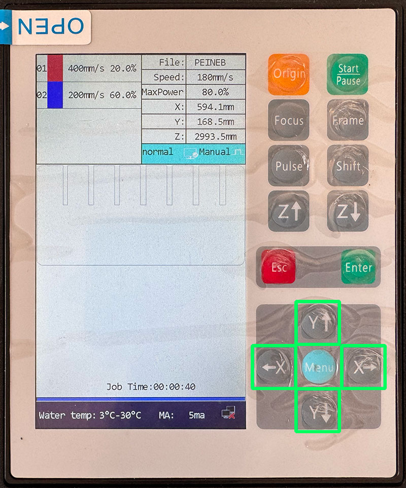
Material placement and origin
- Move the laser head using the control panel (X and Y axes).
- Place the material flat on the bed, aligned with the axes.
- Ensure the red pointer remains inside the material area.
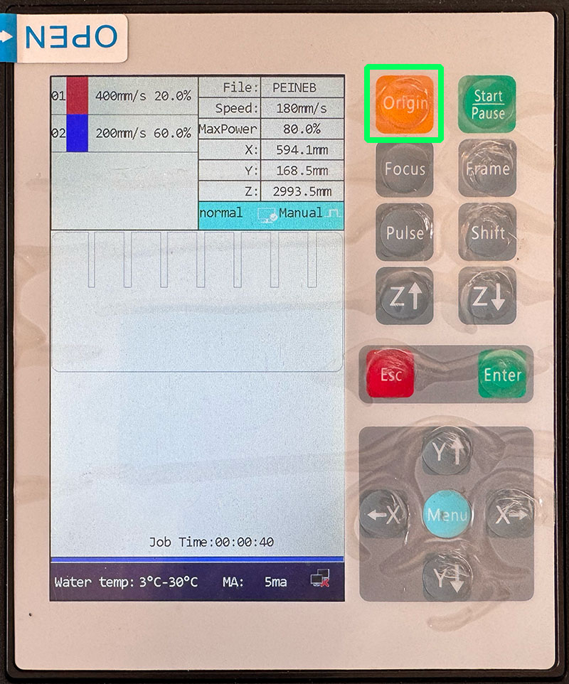
- Move the head to the desired starting point.
- Set this position as the origin.
The default origin of this machine is the top-left corner of the material.
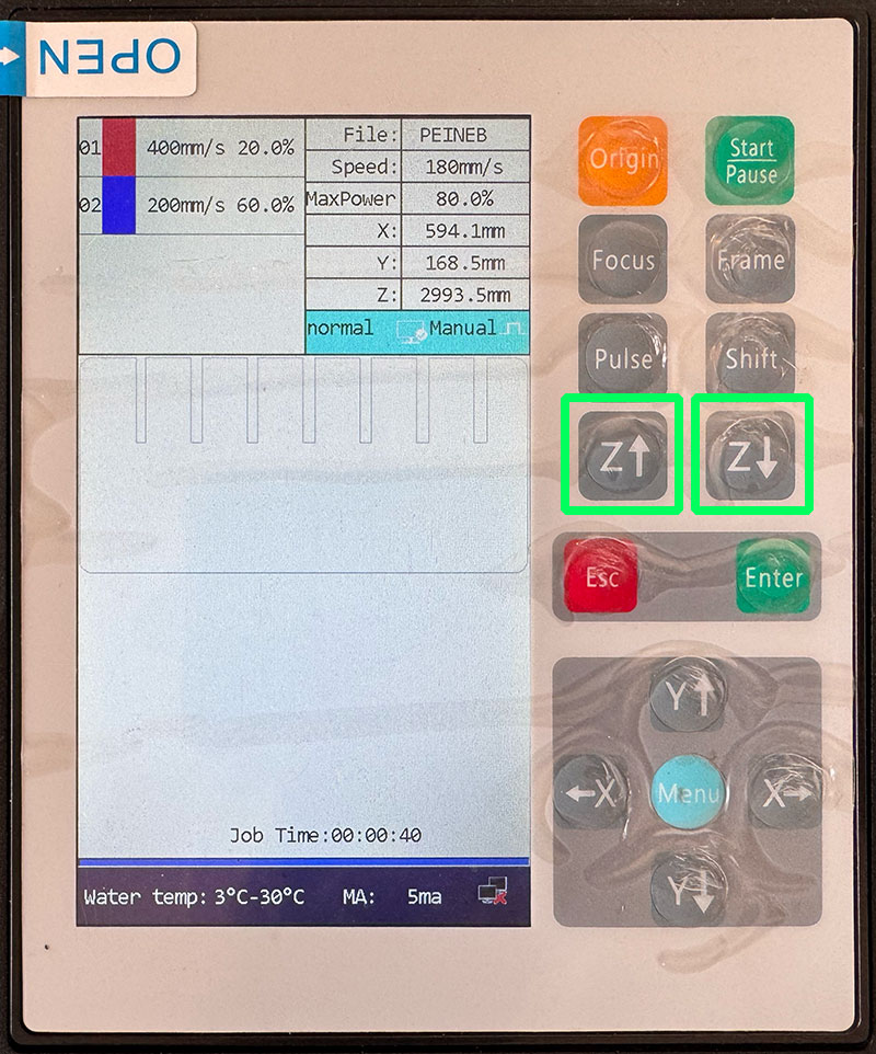
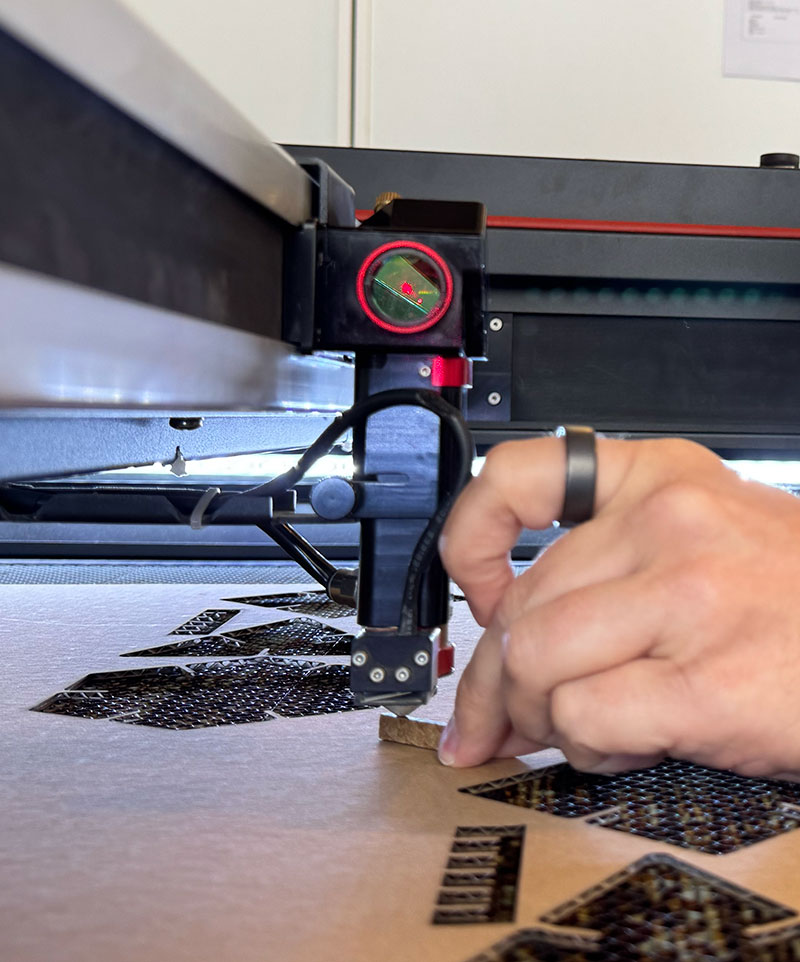
Focusing the laser
Focus distance: 7 mm
- Adjust the bed height using the Z up/down buttons.
- Check the distance using the 7 mm gauge.
- Fine adjustment using the lens tube is possible, but bed movement is recommended.
RDWorks workflow
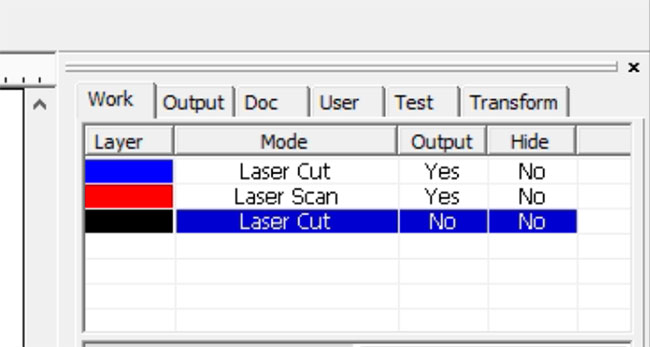
Layers and operations
- No process: reference geometry, output disabled.
- Scan/Raster (escanear): raster engraving.
- Cut/Vector (Corte): vector cutting.
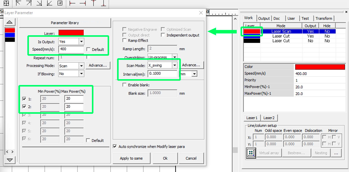
Engraving (Scan/Raster/Grabar)
- Mode: Scan
- Speed: approx. 20–600 mm/s
- Power: approx. 3–90%
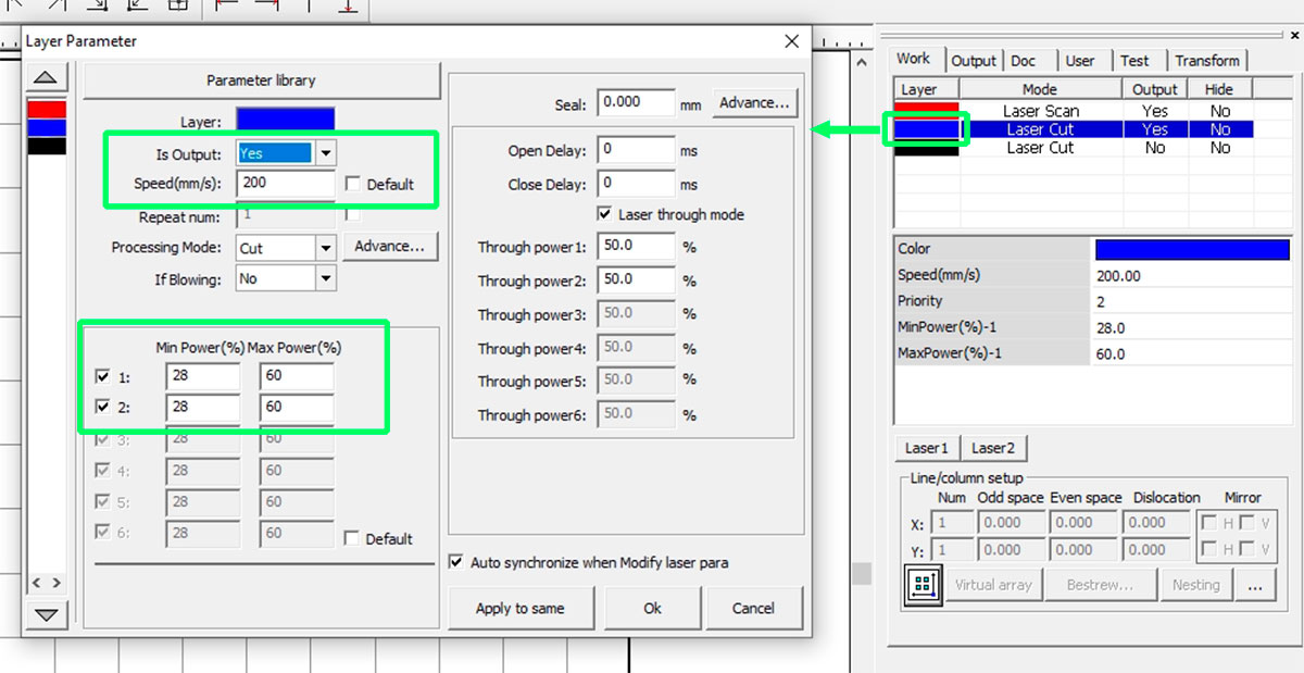
Cutting (Vector/Corte)
- Mode: Cut
- Speed: approx. 4–120 mm/s
- Max Power: straight lines
- Min Power: corners and curves
- Blow Select: LOW
All parameters depend on the material and must be validated with test cuts. To adjust Speed and Power according to the material being used, consult the table of parameters and materials in the FabLab or ask the FabLab. Manager
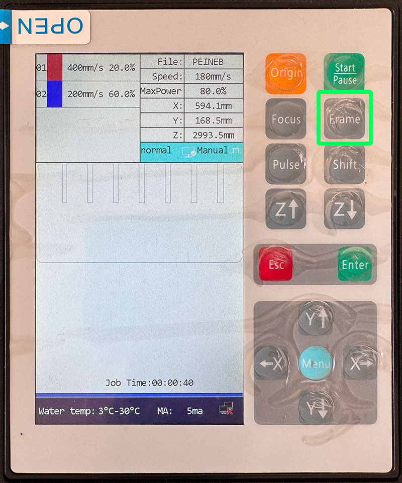
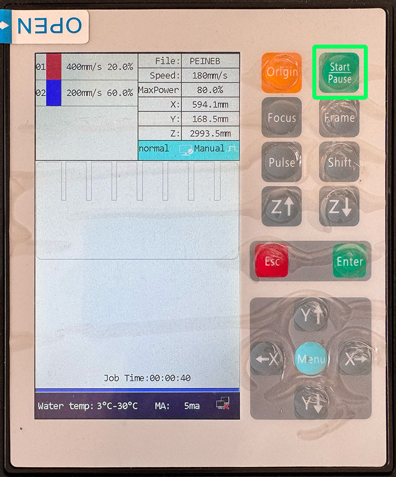
Sending and running the job
- Send the file from RDWorks using Download.
- File name must be a maximum of 8 characters.
- Set origin and focus on the machine.
- Run FRAME to verify the working area.
- Turn on extraction and filtration.
- Close the lid and press START.
To stop a job, press START/PAUSE and then ESC.
Kerf
Kerf documentation by: Efrén García ↗️
Kerf is the width of material removed by the laser beam during the cutting process. When the laser cuts along a vector line, it does not produce a perfectly zero-width cut: a small amount of material is vaporized, generating a measurable gap.
This means that the final dimensions of a cut part are slightly smaller (for external contours) or slightly larger (for internal slots) than the original design. For press-fit constructions and precise assemblies, compensating for kerf is essential.
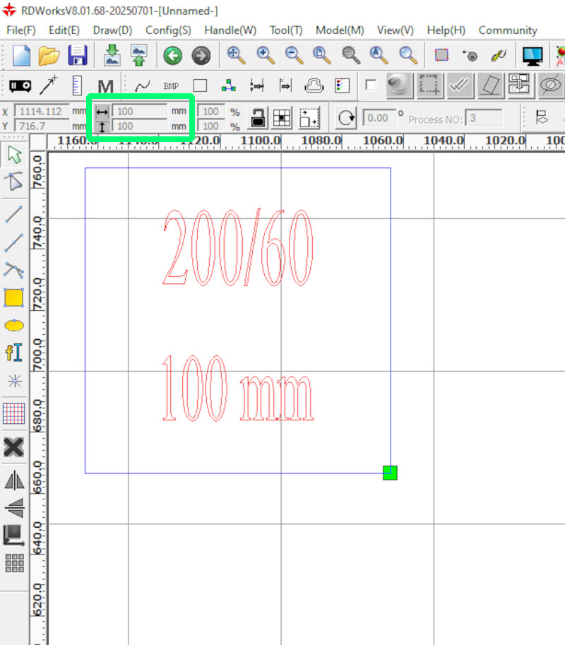
Kerf calculation on this machine
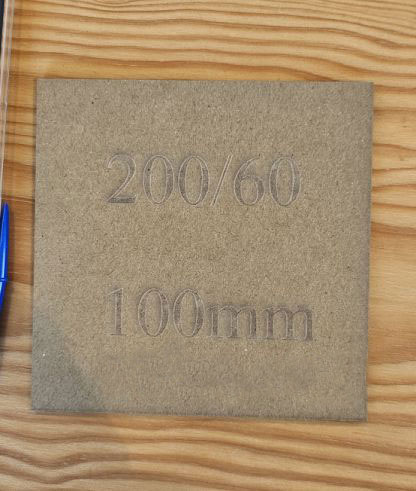
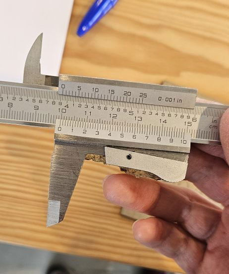
To calculate the kerf of the Framun Laser NOVA ELITE 14, we performed a simple test:
- Designed a square of 100 × 100 mm.
- Cut it in 3 mm wood.
- Measured the final piece using a digital caliper.
The measured result was 99.8 mm instead of 100 mm.
| Designed size | Measured size | Total difference | Kerf per side |
|---|---|---|---|
| 100 mm | 99.8 mm | 0.2 mm | 0.1 mm |
Since the total difference was 0.2 mm, and the laser removes material on both sides of the cut line, the kerf value is:
Kerf may vary depending on the material type, material thickness, focus accuracy, and speed/power settings. For this reason, it is recommended to repeat this test whenever changing material or significantly modifying cutting parameters.
In parametric design, the kerf value can be introduced as a variable so that any change in material or machine configuration can be automatically compensated.
Safety rules
A CO₂ laser cutter combines fire risk, toxic fumes, moving mechanics, and high voltage. Safe operation depends on following a consistent procedure and keeping constant supervision.
1) Fire prevention and response
- Stay next to the machine during the entire job. Small flames can escalate quickly.
- Use Air Assist and proper extraction to reduce flare-ups and keep the cut clean.
- Keep the bed clean: small offcuts and debris can ignite.
- Know where the emergency stop and the fire extinguisher are located.
- If you see a persistent flame or abnormal smoke: pause/stop the job immediately and follow the lab protocol.
2) Fumes, ventilation, and material hazards
- Always turn on extraction/filtration before starting the job.
- If you smell strong fumes in the room, stop the job and check the extraction system.
- Never cut PVC / vinyl / chlorinated plastics (toxic and corrosive gases).
- Avoid unknown materials. When in doubt: don’t cut it.
- After finishing, wait a few seconds before opening the lid to let fumes evacuate.
3) Laser exposure and interlocks
- Keep the lid closed while the laser is firing.
- Do not defeat or bypass safety interlocks.
- Do not stare at the beam impact point for long periods (even through the window).
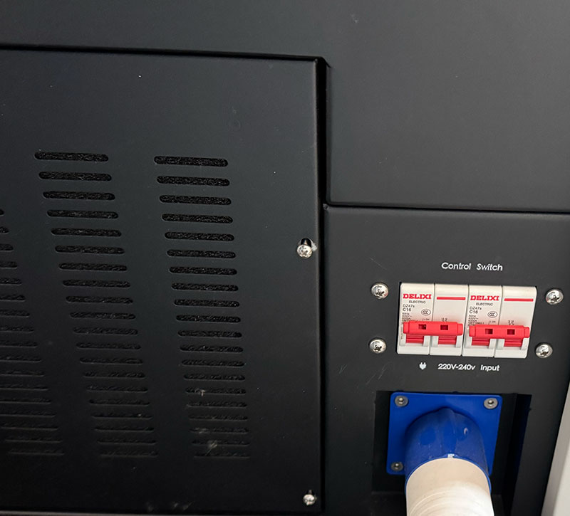
4) High voltage and maintenance boundaries
- Do not open electrical compartments: CO₂ laser systems use high voltage.
- Do not touch the laser tube, PSU, or internal wiring.
- Only trained staff should perform maintenance beyond basic cleaning.
5) Moving parts and workspace safety
- Keep hands clear of the gantry and belts when the machine is moving.
- Avoid loose clothing or accessories that could snag.
- Make sure the material is flat to avoid head collisions and focus errors.
6) Optics and bed cleanliness (safety + quality)
- Dirty lenses/mirrors can overheat, reduce cutting performance, and increase fire risk.
- Clean the bed and remove debris after each job.
- If you notice unusual smoke, weak cutting, or frequent flare-ups, stop and ask the lab manager to check optics/alignment.
Safety checklist (visual)
Quick checklist I follow before starting and while running a job on the laser cutter.