Roland monoFab · SRM-20
Compact CNC milling — Operation and Safety
Overview
The Roland monoFab SRM-20 is a compact 3-axis CNC milling machine designed for prototyping, small machining jobs, and detailed work. Compared with a large CNC machine, the focus here is not on removing large amounts of material or working on big boards, but on achieving precision, cleanliness, and control in small parts, molds, engravings, and especially, in a Fab Lab environment, PCBs and small-format components.
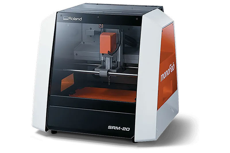
Another major advantage is that it is a very suitable machine for the classroom or laboratory: it takes up little space, works with a simple interface through VPanel, and makes the process easy to control. Even so, it is still a real milling machine, so it should be used with the same respect as any other CNC.
Machine specifications
| Parameter | Value |
|---|---|
| Model | Roland monoFab SRM-20 |
| Machine type | Compact desktop CNC milling machine, 3 axes |
| Maximum work area | 203 × 152 × 60.4 mm |
| Acceptable material | Resins such as chemical wood and modeling wax; machining substrates |
| Maximum spindle / rotor speed | 7000 rpm |
| Tool holding | Collet / collar system |
| Interface | USB |
| Commands | RML-1, NC code |
| Power consumption | Approximately 55 W |
| Noise level | ≤ 65 dB(A) while operating without cutting; ≤ 45 dB(A) on standby |
| Dimensions | 451.0 × 426.6 × 426.2 mm |
| Weight | 19.6 kg |
| Recommended environment | 5–40 °C, 35–80 % RH non-condensing |
| Associated software | VPanel, SRP Player, MODELA Player 4, iModela Creator, ClickMILL, Virtual MODELA |
The actual machining capability depends on the material, the tool, the cutting depth, and the chosen strategy. Although it is a precise machine, it is not intended for aggressive machining.
Compatible materials
- Modeling wax
- Chemical wood / modeling resins
- Machinable foams
- Acrylic
- Polyacetal
- Sheet ABS and PC
- PCB machining substrates
Machine operation summary
The full process is described in more detail below with examples
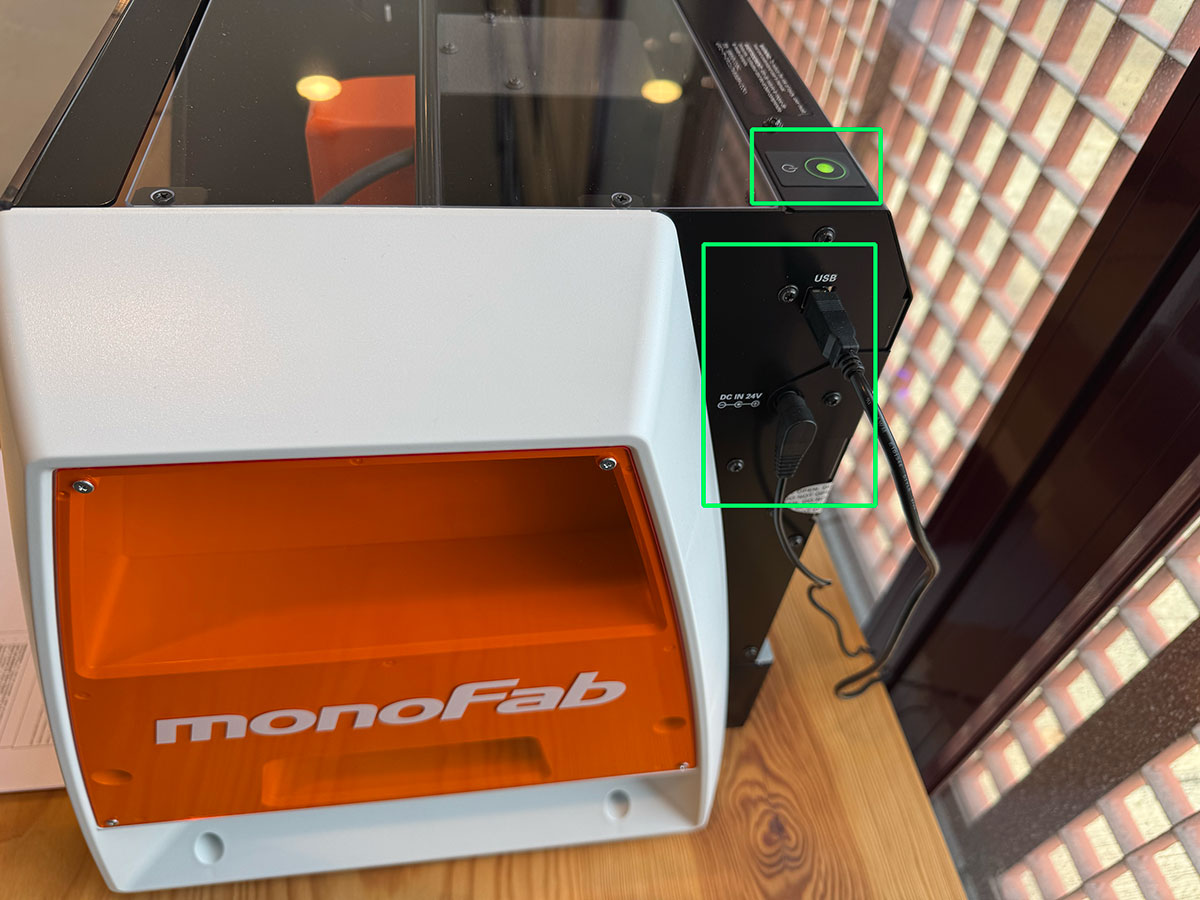
1. Initial startup
- Check that the work area is clean and that there are no loose tools inside the enclosure.
- Turn on the SRM-20 and connect the computer if it is being controlled externally.
- Open VPanel for SRM-20.
- Verify that the machine responds correctly to manual movements.
2. Material placement and fixing
- Prepare the base and clean both the bed and the underside of the material.
- Fix the material using double-sided tape, which is useful for thin pieces and PCBs, or with the appropriate clamping system.
- Check that the material is completely flat and does not move.
- Make sure the tool has enough travel without hitting clamps or edges.
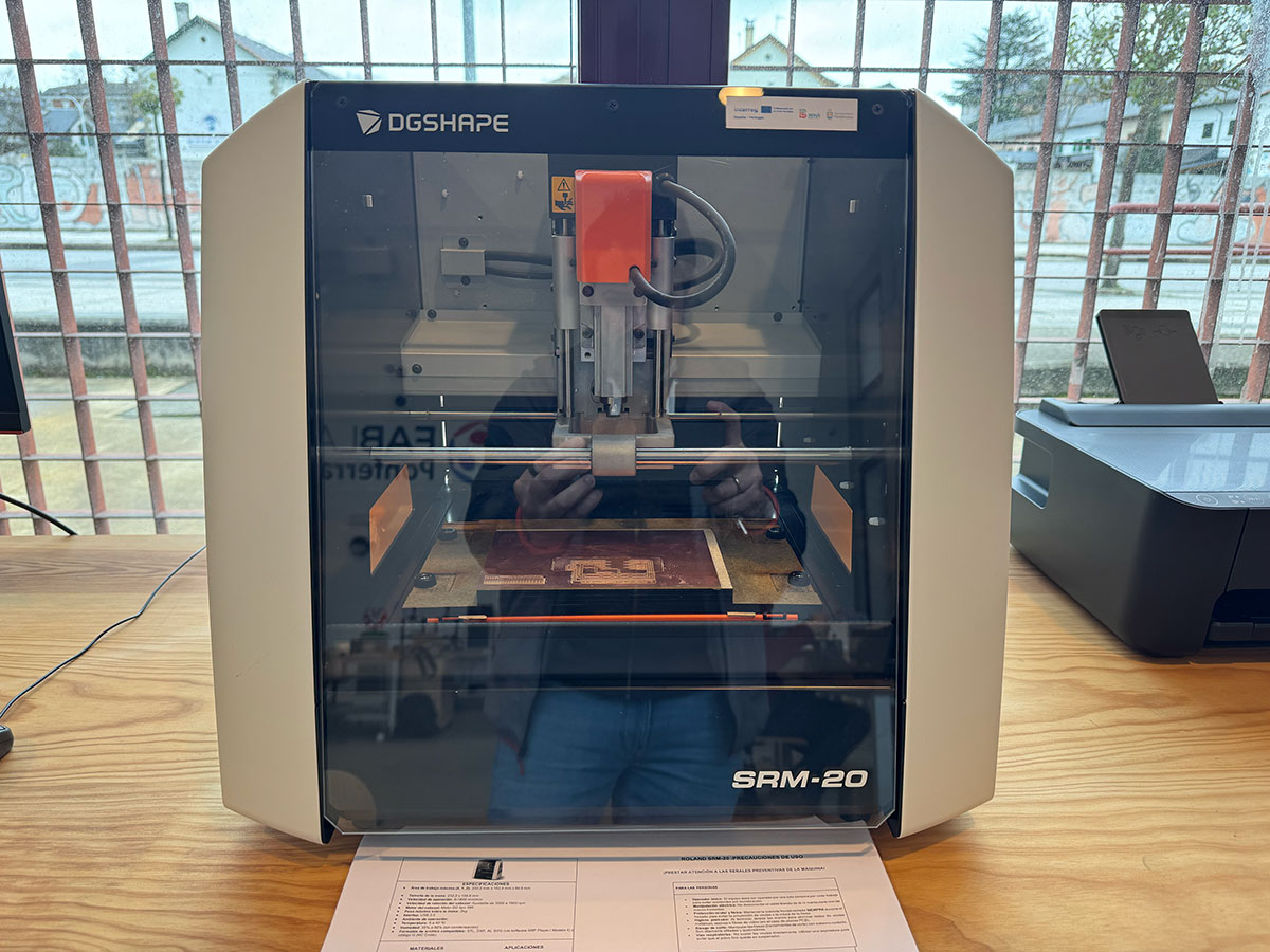
On this machine, clamping is critical. A poorly attached board or a slightly lifted part can cause the cutting depth to vary, which is especially critical when milling a PCB.
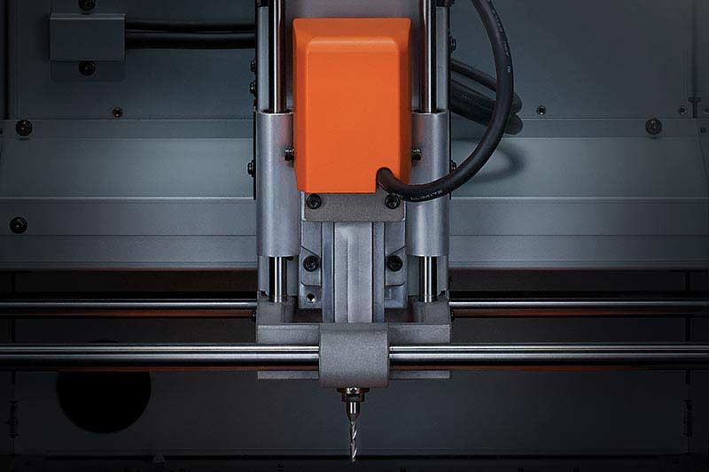
3. Tool placement
- With the machine stopped, loosen the collet and insert the appropriate tool.
- Leave enough useful length for machining, but avoid letting it stick out more than necessary.
- Tighten it properly before moving or starting the spindle.
4. Define the work origin
- Using VPanel, move the tool to the desired start position.
- Set the X/Y zero at the chosen corner or reference point.
- Carefully lower the Z axis until it approaches the surface.
- Slightly loosen the tool, let it touch the surface of the material, and tighten it again.
- Register the Z zero.
The Z axis is the most delicate point. If it is too high, the tool will not cut enough; if it is too low, the tool may break or remove too much material at once.
5. Start the job
- Load the previously generated machining file.
- Check that the tool, zero, material, and strategy match the file.
- Start the spindle and begin the job.
- Always monitor the first seconds of milling to detect whether the depth and the path are correct.
6. End of the process
- Wait until the spindle has completely stopped.
- Remove the material carefully.
- Clean any dust, chips, or fibers before leaving the machine ready for the next person.
VPanel and associated software
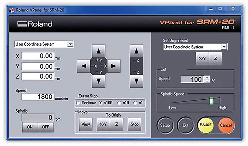
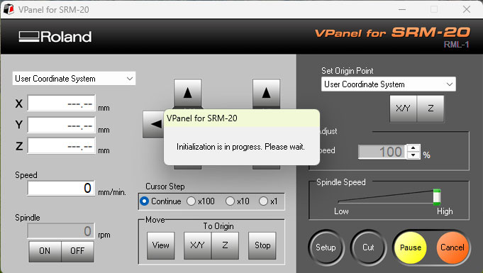
The SRM-20 uses VPanel as its main manual control interface. From there, it is possible to move the axes, define the origin, adjust the machine behavior, and launch or supervise the process. It is a simple interface, and precisely for that reason it is very convenient for learning and for repeatable jobs.
Roland also associates the machine with several programs for different needs:
- SRP Player: step-by-step CAM for 3D machining and path preparation.
- MODELA Player 4: intuitive CAM processing for STL files and cutting strategy control.
- iModela Creator: useful for drawings, text, and simple 2D work.
- Virtual MODELA: simulation and prior job estimation.
- ClickMILL: direct operations such as holes, pockets, or finishing without needing full CAD/CAM software.
PCB production
Start from a PCB previously designed in a CAD program, for example KiCad, from which the Gerber output files will be generated.
Example of the complete workflow from a PCB already designed in KiCad to the final processing:
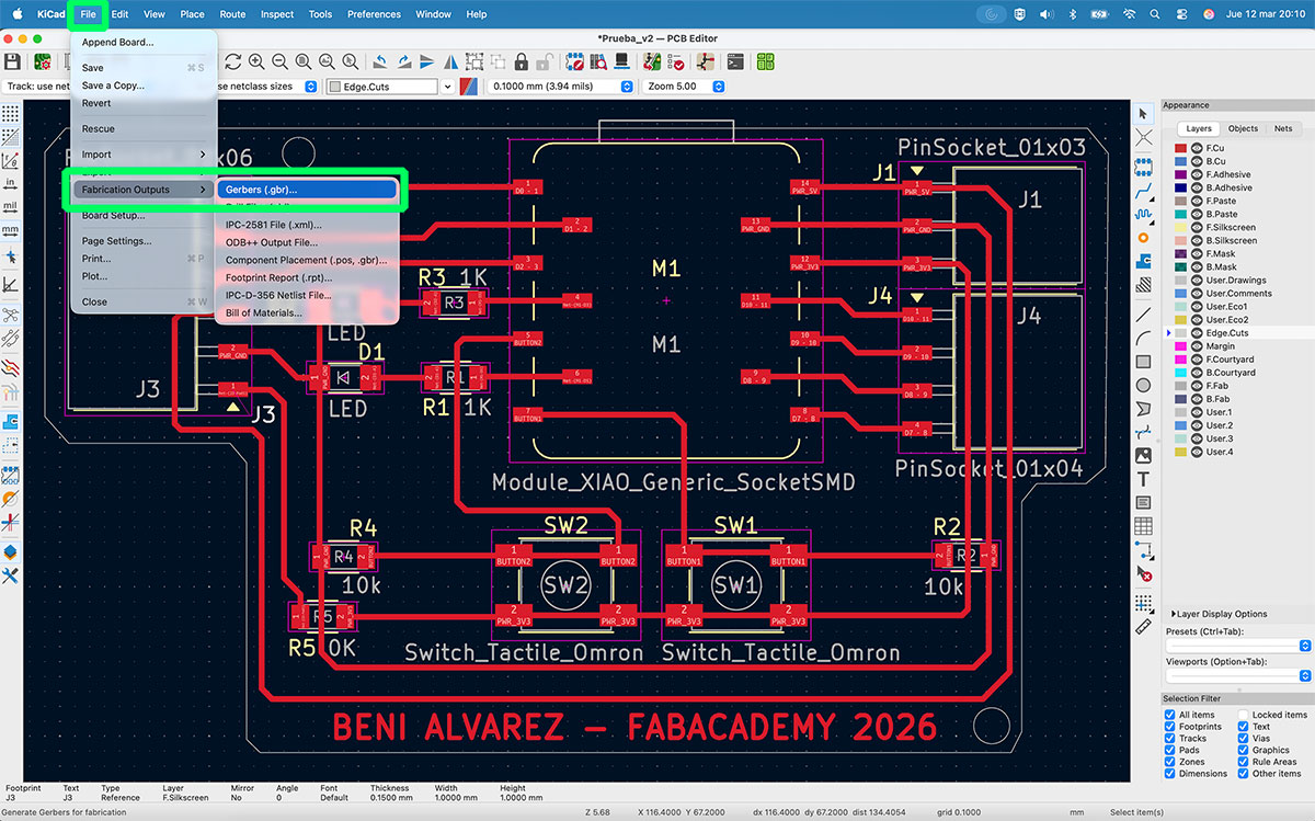
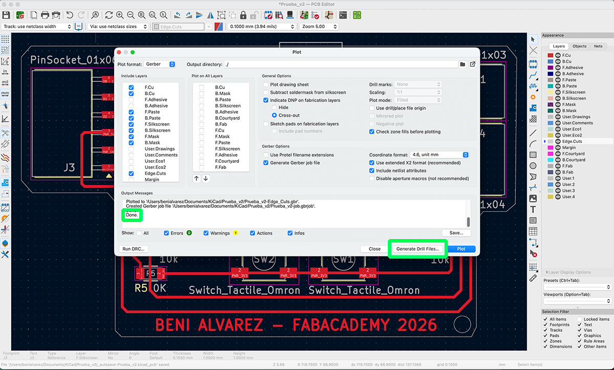
Start by opening the PCB project in KiCad and going to File → Fabrication Outputs → Gerbers (.gbr).
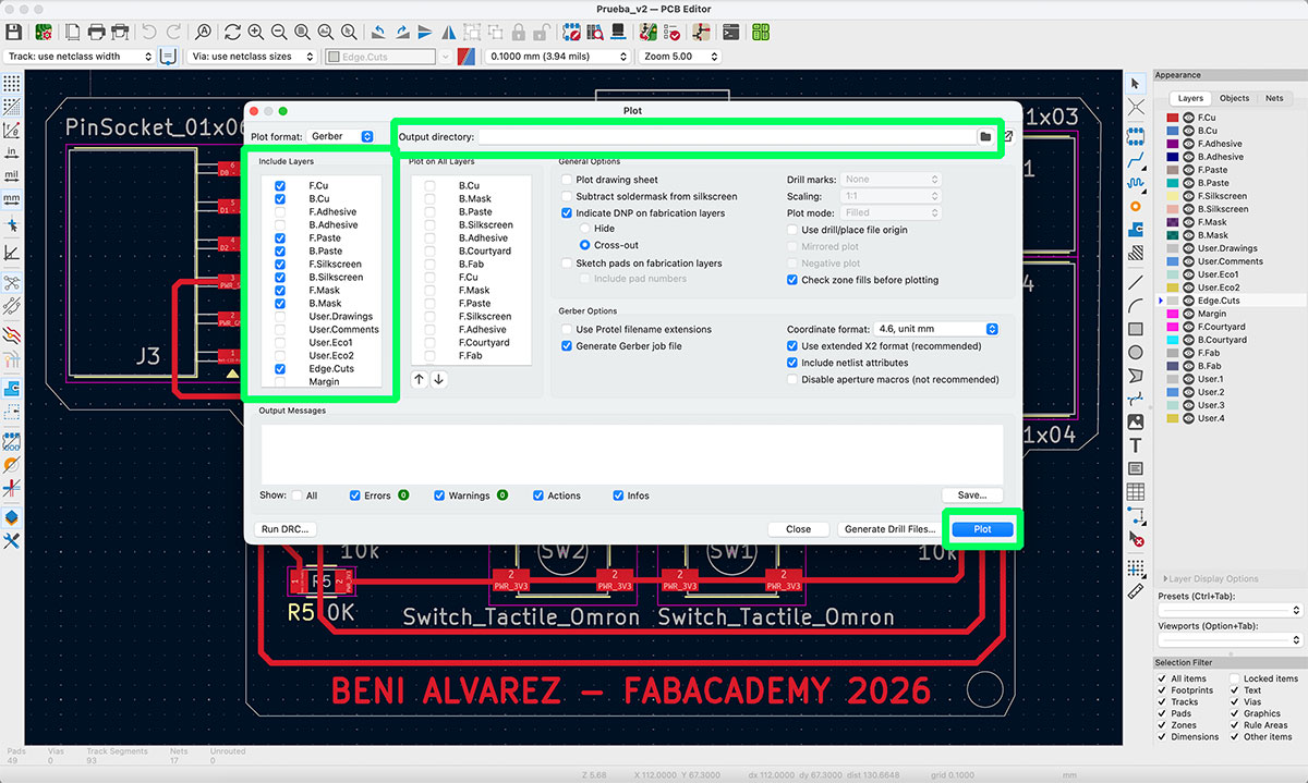
In the Gerber export window, select the destination folder where the files will be saved, choose the layers required for fabrication, and then click “Plot” to generate the Gerber files. Once the message “Done” appears, continue with the generation of the drill files.
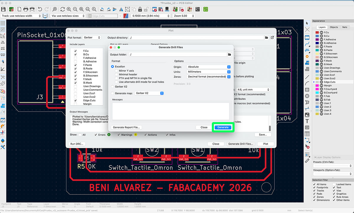
To generate them, click “Generate Drill Files…”. This will open a new dialog window where you simply need to click “Generate” so that KiCad also creates the drill data.
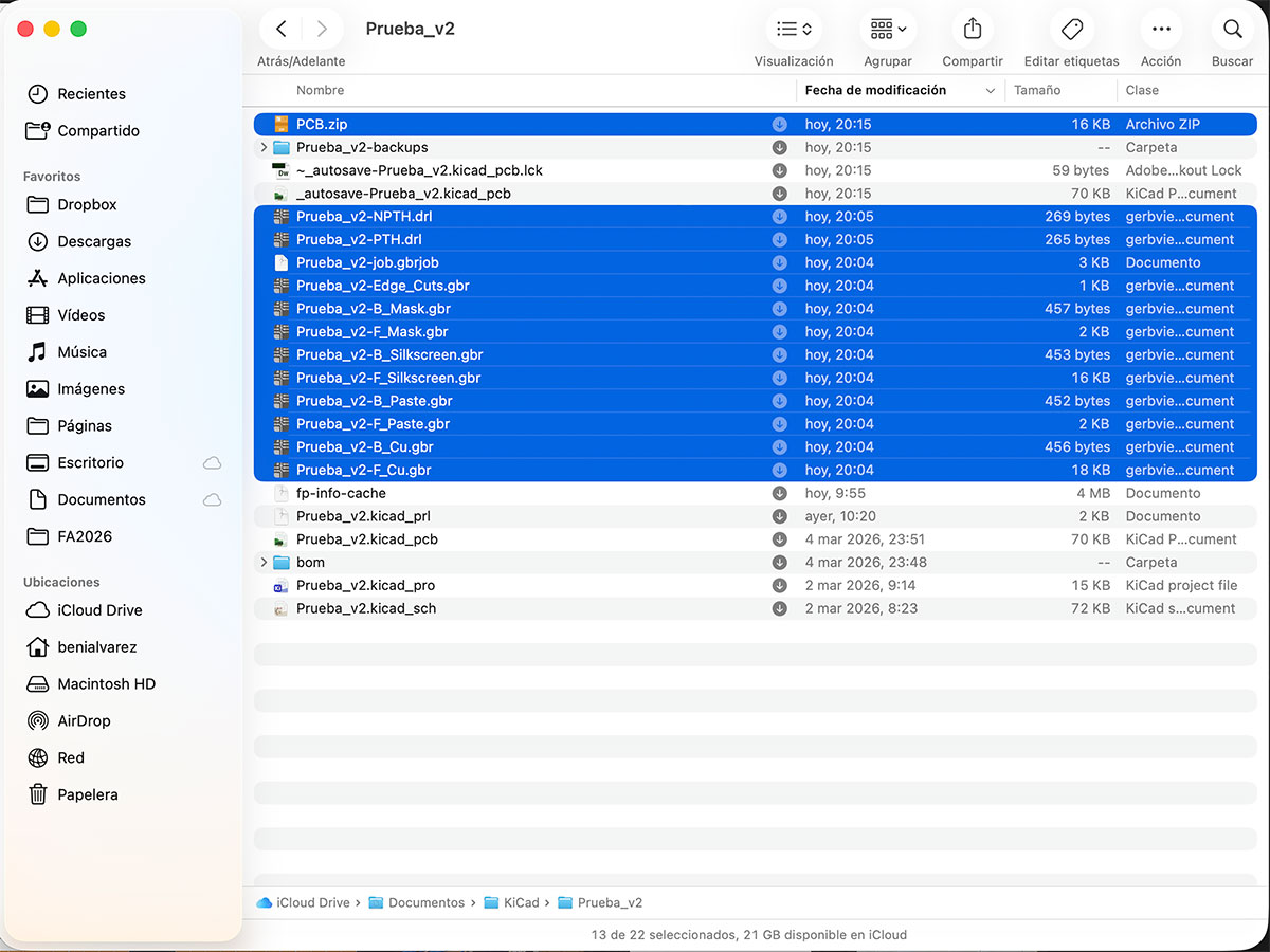
Then go to the output folder and check that the process has generated a total of 12 files. These files include both the different board layers and the drill information required for fabrication.
To make file uploading easier, compress all the generated files into a single .zip file. For example, it can be named “PCB.zip”.
This same .zip file will later be used in the different stages of the PCB fabrication process.
Generate images from the PCB Gerbers
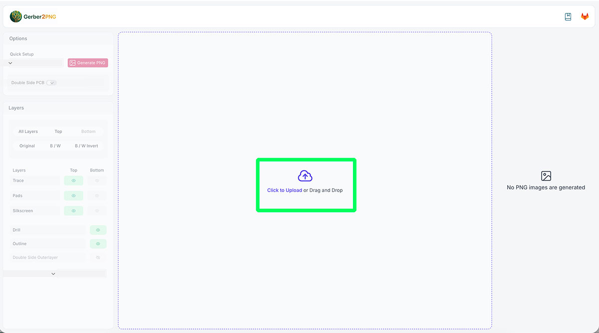
Once the Gerber files have been generated, the next step is to convert them into PNG images that will later be used to generate the PCB milling toolpaths.
For this step, use the Gerber2PNG tool, developed by FabLab Kerala, available at: https://gerber2png.fablabkerala.in ↗️
This tool allows you to upload directly the same .zip file previously generated in KiCad, which contains both the Gerber files and the drill files.
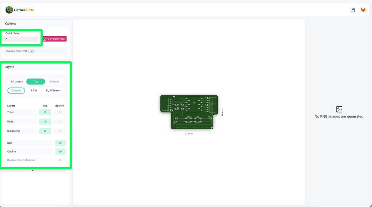
As soon as the compressed file is uploaded, the platform automatically displays a preview of the PCB. This makes it easy to quickly check that the design has been loaded correctly.
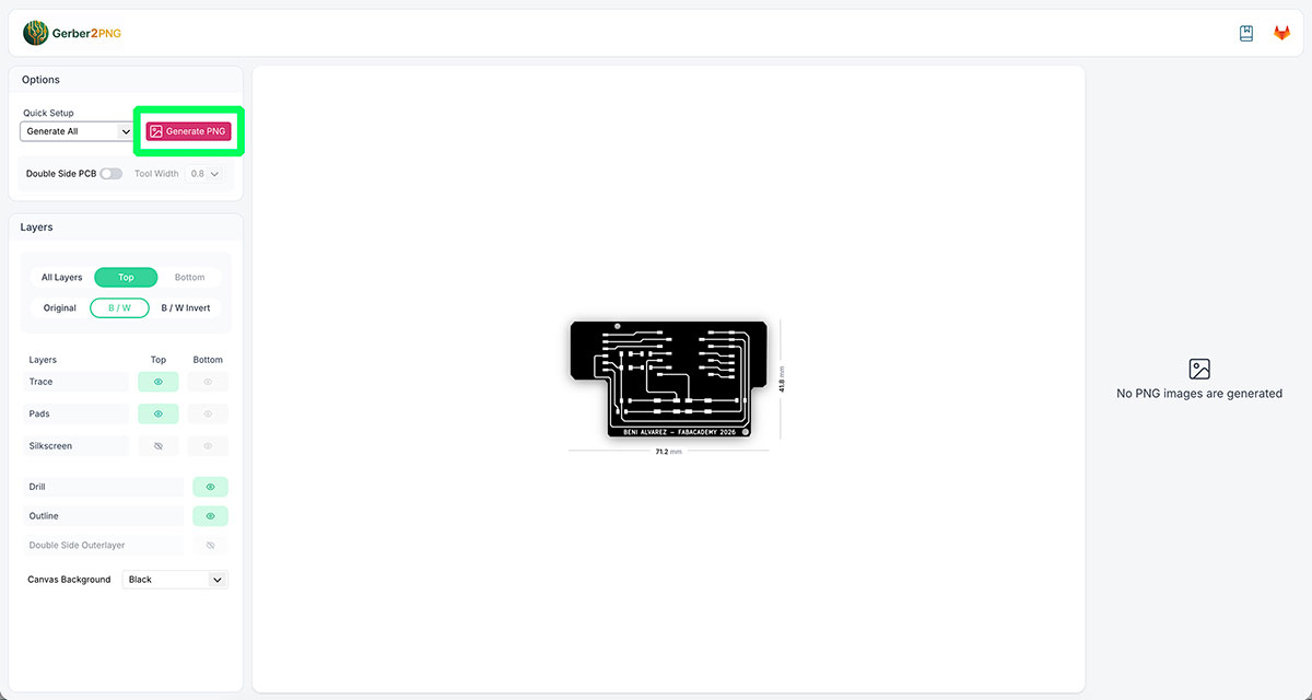
Next, configure the generation options. First select “Generate all” so that the system creates all the required files. In the Layers section, enable the “B/W” layer and disable “Silkscreen”, since in this case the component silkscreen will not be milled.
Also check that the “Quick Setup” section still has the “Generate all” option selected, since this setting may change automatically when modifying other parameters.
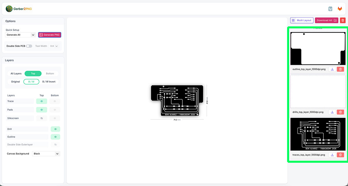
After configuring everything, click “Generate PNG”. A few seconds later, the right-hand column will display the three generated PNG files, corresponding to the outline, the drills, and the traces of the board. These are the files that will later be downloaded and used in the milling process.
In these images, the color code is important: the white areas represent the copper that will remain on the board, while the black areas correspond to the material that will be removed by the milling tool.
Later, when configuring the machining toolpaths, the number of tool passes will determine how much material is removed around the traces to isolate the connections correctly.


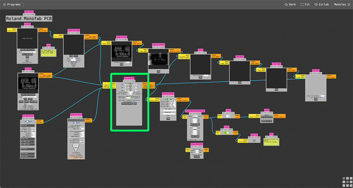
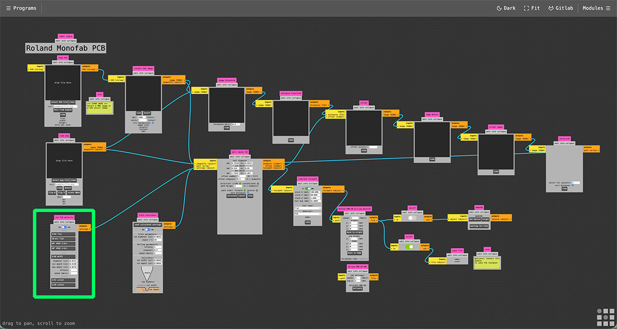
Mods Project
Once the PNG images have been downloaded, the next step is to generate the toolpath files that the milling machine will use to machine the PCB.
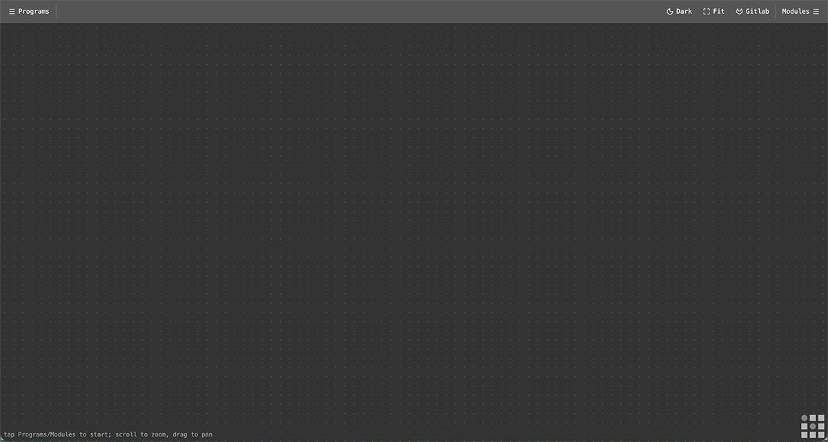
For this step, use the web application Mods Project,
available at: https://modsproject.org/ ↗️
This tool is designed to work with digital fabrication machines and is optimized to run in Google Chrome.
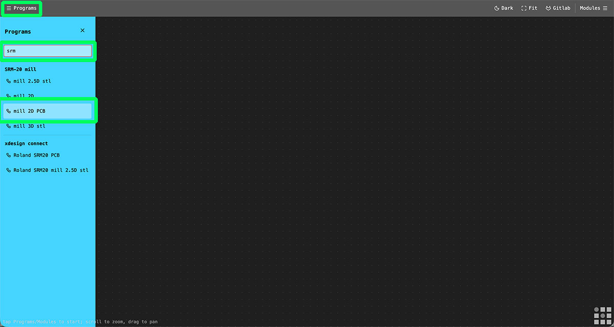
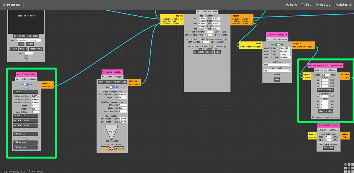
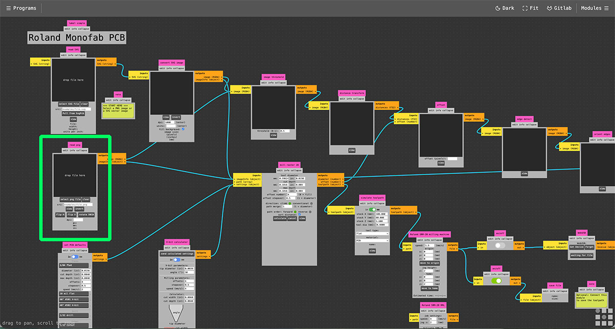
Once on the website, open the “Programs” menu. In the search field type “srm” so that the platform shows the available workflows related to Roland milling machines. In this case, select “mill 2D PCB”, which loads the workflow specifically designed for milling PCBs with this machine.
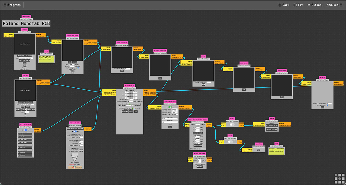
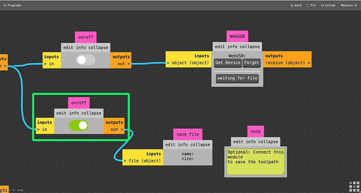
At the end of the workflow there are two output modules. One allows the files to be sent directly to the milling machine via WebUSB, while the other allows the generated files to be saved. In this case, it is better to generate and save the files, since they will later be loaded into the machine using the dedicated VPanel software. To do this, go to the end of the workflow and activate the “Save file” option.
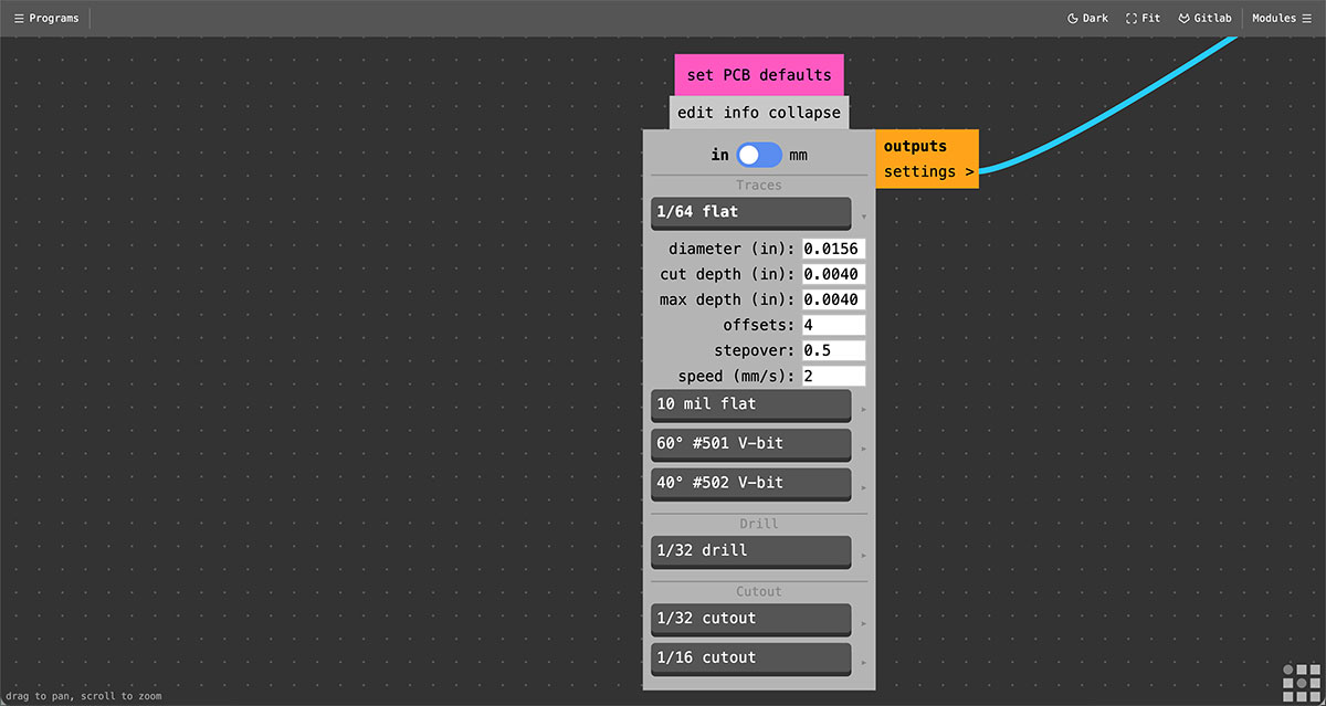
Then return to the first part of the workflow to configure the machining parameters. In the lower section of the corresponding module, it is possible to define the “Traces” parameters depending on the type of end mill that will be used.
In this case, select “1/64 flat” from the menu on the right. Once selected, the parameters associated with that tool appear automatically. Keep all the default values except for the speed, which can be adjusted to 2 mm/s. After changing the value, it is important to click the “1/64 flat” button again so that the configuration is applied correctly.
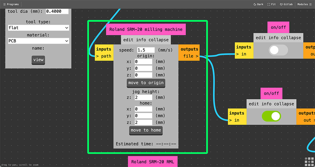
It is also necessary to adjust the speed in the “Roland SR-20 milling machine” module, which appears later in the workflow. In this module, set the toolpath speed to 1.5 mm/s.
The same module also defines the machine origin and home positions. A common configuration is the following:
Origin: X:0, Y:0, Z:0 mm
Jog height: 2 mm
Home: X:0, Y:0, Z:2 mm
Setting the Z axis to 2 mm in the Home position ensures that the milling tool starts slightly above the surface, preventing the bit from starting in direct contact with the PCB.
Generate the traces toolpath
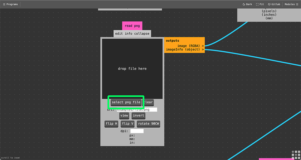
Once the parameters have been configured in Mods, the next step is to load the previously generated images in order to create the milling toolpaths. Start with the traces file.
At the beginning of the Mods workflow there are two image input modules: PNG and JPG. Load the file in the corresponding module and the workflow will automatically update to show the PCB image in the following modules of the process.
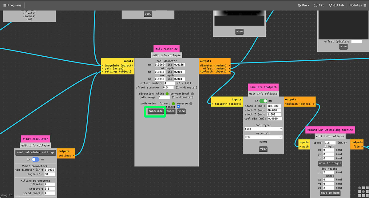
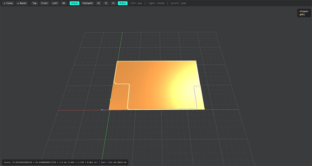
In the central part of the workflow is the “mill raster 2D” module, which is responsible for calculating the milling paths from the loaded image.
To generate the toolpath, click the “Calculate” button. After doing so, the system processes the image and generates several intermediate visualizations in the boxes above, such as “offset”, “edge detect”, and “origin edges”. These views help verify how the design is being interpreted before creating the final file.
At the same time, Mods generates the machine control file in .rml format. This file is automatically created using the same name as the loaded image. In this case, the generated file was:
traces_top_layer_1000dpi.png.rml
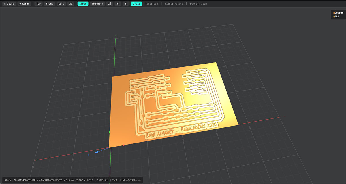
Once the file is generated, it automatically opens in a new browser tab or window, showing a preview or simulation of the milling path that the tool will follow on the PCB.
It is important to keep in mind that the first time this process is run, the browser may block the new window. In that case, it is necessary to allow pop-ups for the Mods website and repeat the process.
After generating the traces toolpath, the next step is to repeat the same process with the other two previously generated images: drills and outline.
In both cases, use a 1/32” end mill, suitable for drilling the holes and cutting the outer contour of the PCB. In the corresponding module, select “1/32 flat”, keeping all the default parameters except for the speed, which is adjusted to 2 mm/s.
As before, it is also necessary to configure the toolpath speed in the “Roland SR-20 milling machine” module. In this case, the speed is also set to 2 mm/s.
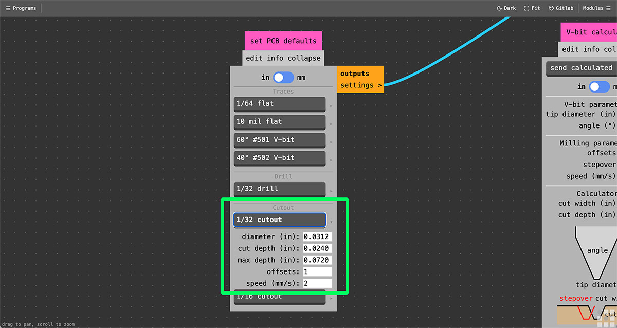
In the “Set PCB defaults” module, configure the specific parameters for each operation:
1/32” drills to generate the holes.
1/32” cutout for the outer PCB cut.
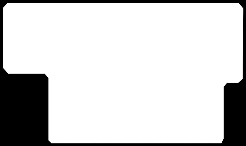
During this step, it can be seen that the outline image also contains the drill holes. To prevent the milling machine from interpreting both operations in the same file, it is best to separate them into two different images.
To do this, edit the image in GIMP. Create one file containing only the PCB outline (removing the drill circles) and another file containing only the drills.
In this way, independent toolpaths can be generated for each operation, allowing better control of the machining order and ensuring that the correct tool is used in each process.


Once the files are ready and the corresponding tools are configured, repeat the same procedure to generate the drilling toolpaths.
To do this, load the image corresponding to the holes and configure the tool parameters and machining type in the “Set PCB defaults” module, selecting the appropriate end mill and the drill toolpath option.
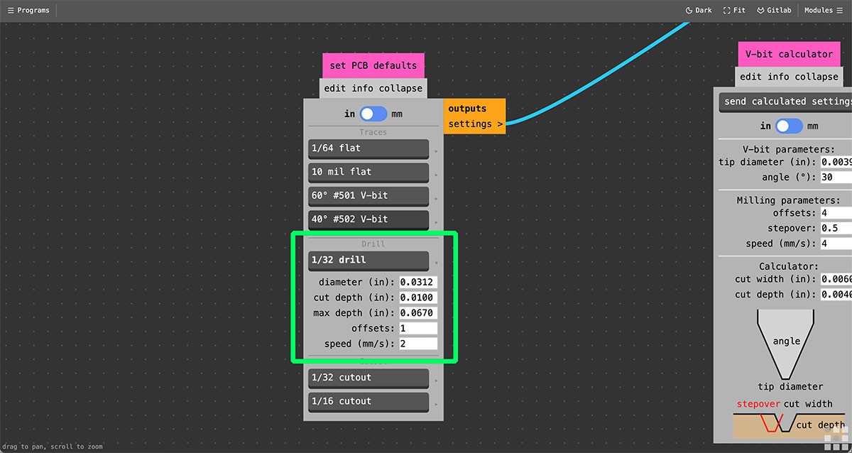
Then repeat the same process to generate the outline cut toolpath. Once again, load the image corresponding to the PCB outline and configure the parameters in the “Set PCB defaults” module, selecting the tool and the appropriate cutout toolpath option.
SRM-20 milling parameters
| Tool | Diameter | Feed rate |
|---|---|---|
| 1/32” End Mill | 0.8 mm | 2 mm/s |
| 1/64” End Mill | 0.4 mm | 1.5 mm/s |
| Micro End Mill | 0.3 mm | 1 mm/s |
SRM-20 machine parameters
| Machine parameter | Axis | Value |
|---|---|---|
| Origin | X | 0 mm |
| Y | 0 mm | |
| Z | 0 mm | |
| Jog height | Z | 2 mm |
| Home | X | 0 mm |
| Y | 0 mm | |
| Z | 2 mm |
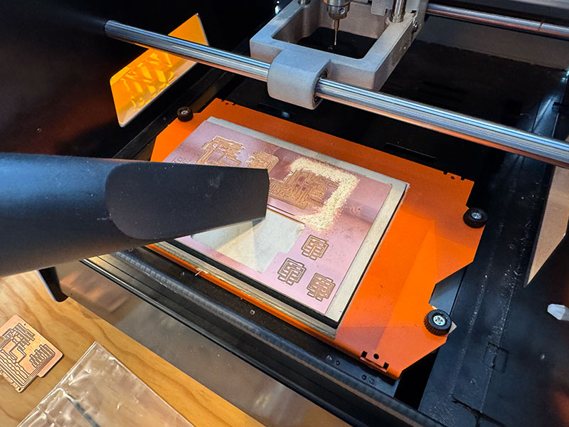
Milling the PCB on the Roland SRM-20
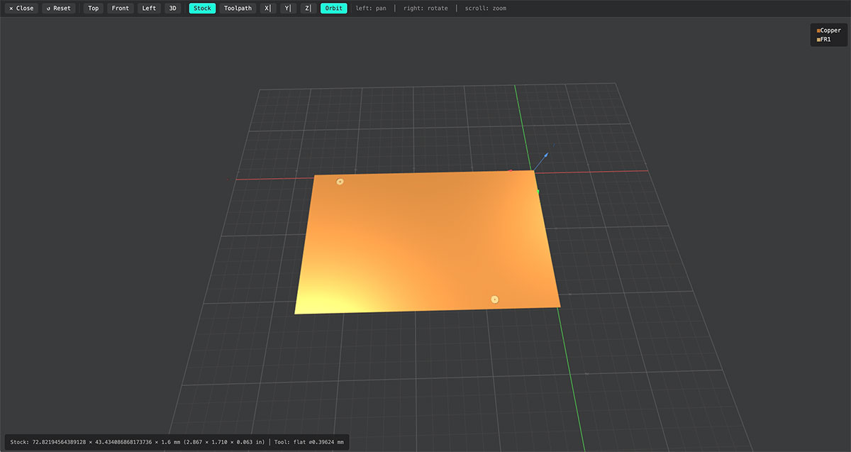
Once the .rml files have been generated in Mods, the next step is to mill the PCB using the Roland SRM-20. This process involves both the physical preparation of the machine and the job setup using the Roland VPanel software.
Physical preparation of the machine
The first step is to prepare the work surface. Fix the PCB to the machine bed using double-sided tape, placing it on top of the sacrificial layer to ensure that the board is firmly held during milling.
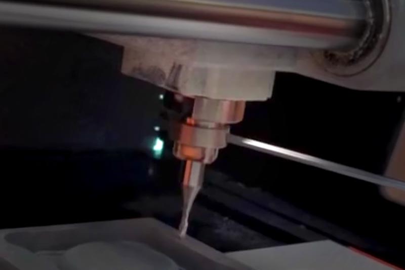
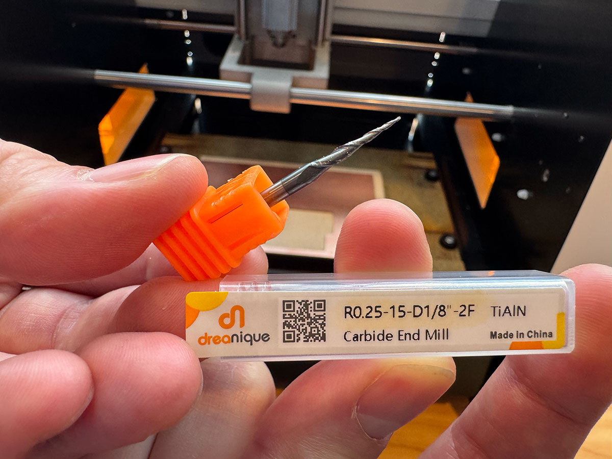
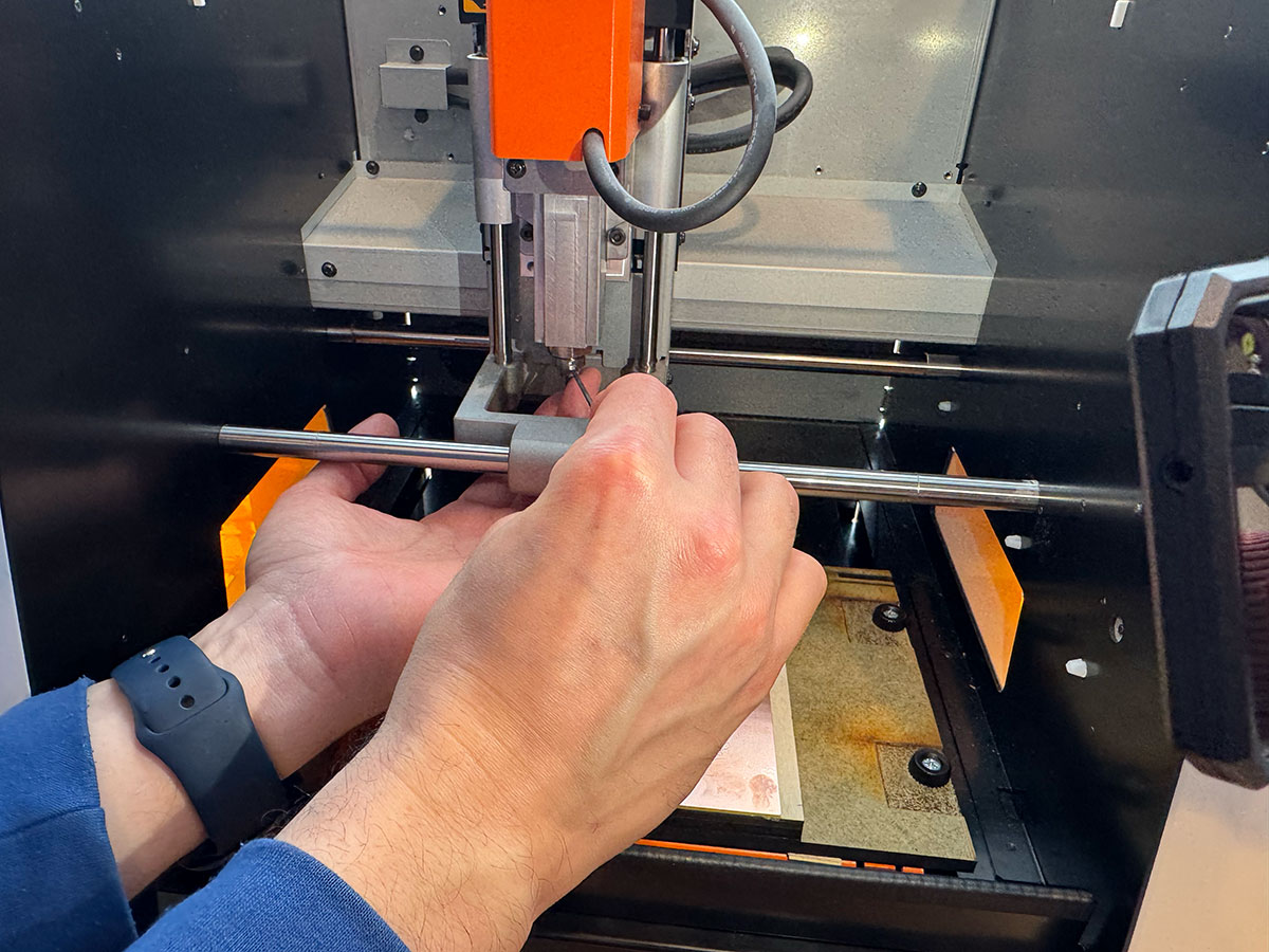
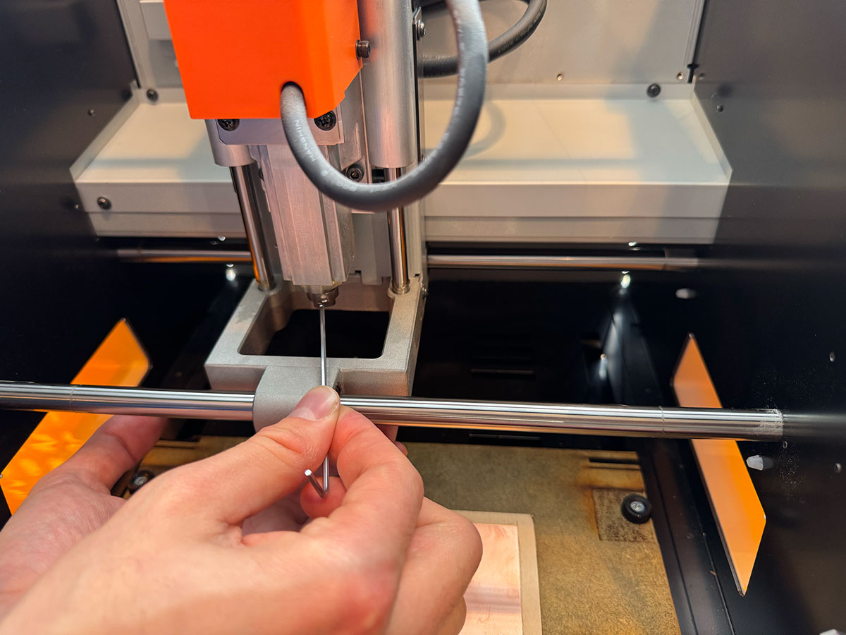
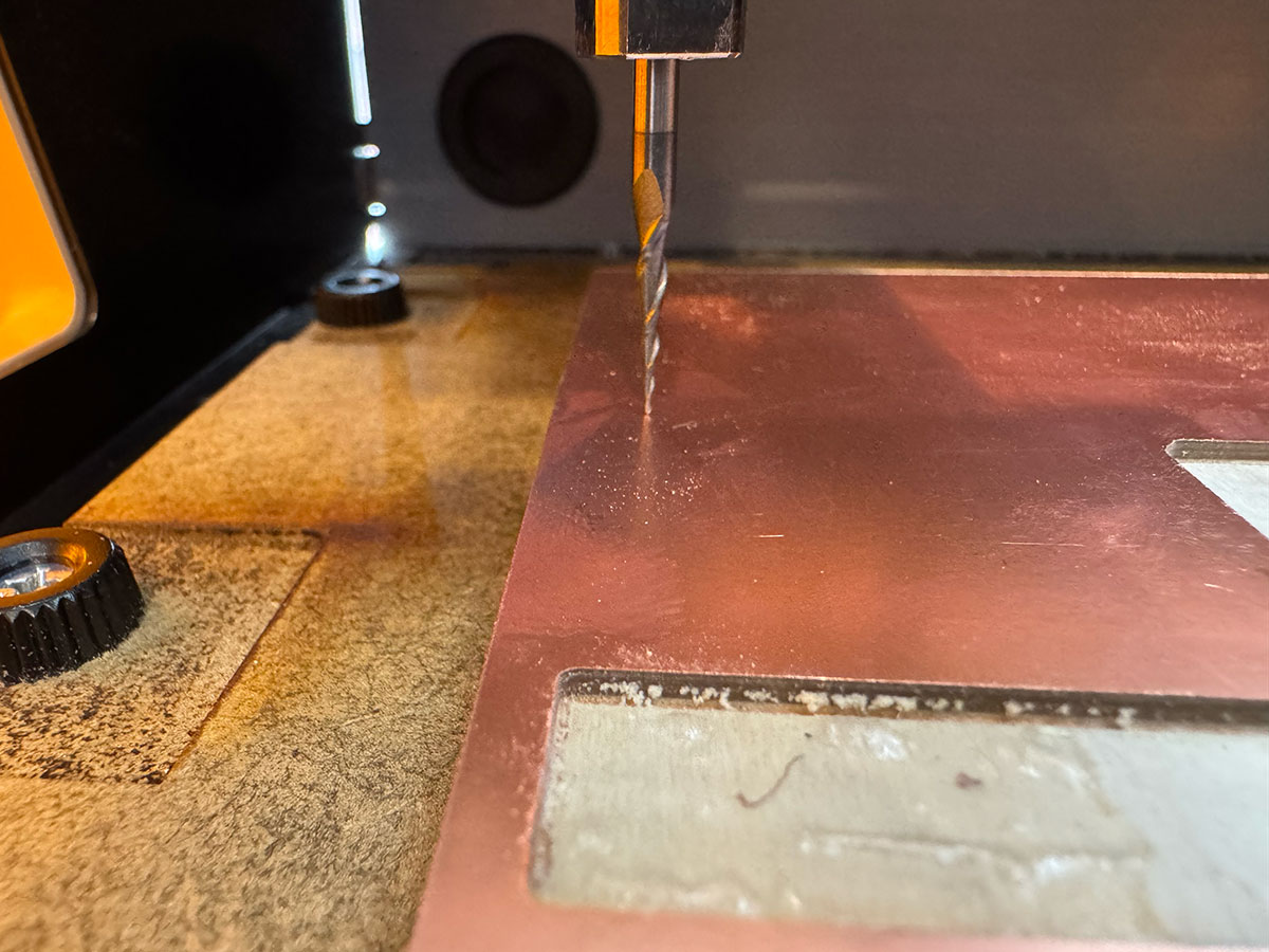
Then install the 0.4 mm (1/64”) end mill, which is used to mill the PCB traces. The tool is inserted into the collet and secured by tightening the fixing screw. It is important that only one person handles the tool during this step to avoid unexpected movement or possible accidents.
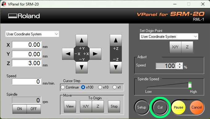
Set the origin in VPanel
With the machine prepared, the next step is to define the milling origin using the Roland VPanel software.
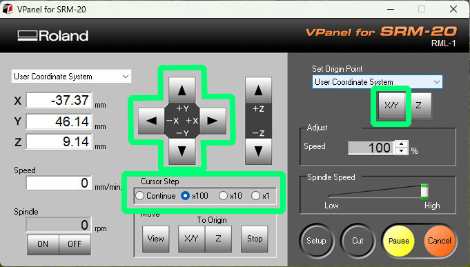
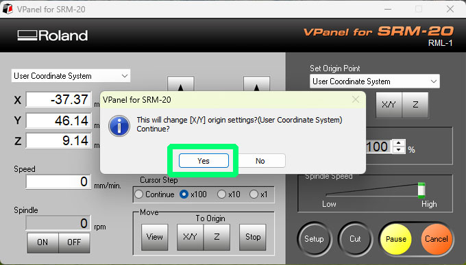
First set the X and Y origin. Using the movement controls in VPanel, position the tool over the desired point on the PCB and click “Set Origin Point – XY” to save that position.
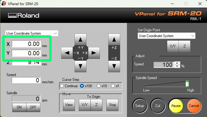
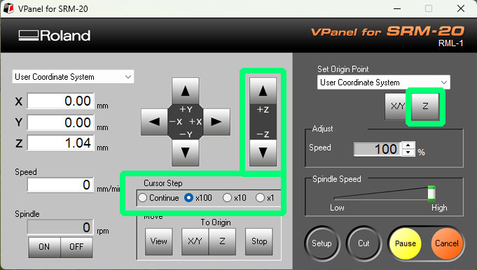
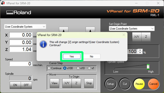
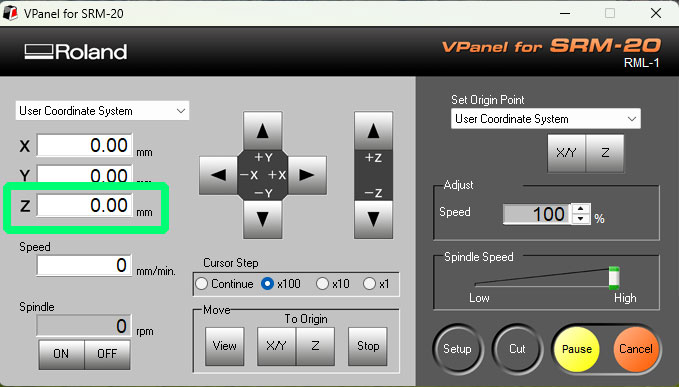
Then set the Z origin following the usual procedure:
1. Lower the Z axis until the tool is as close as possible to the PCB surface using the movement controls.
2. Slightly loosen the tool screw and let the bit rest gently on the PCB surface.
3. Tighten the screw again to fix the position and click “Set Origin Point Z”.
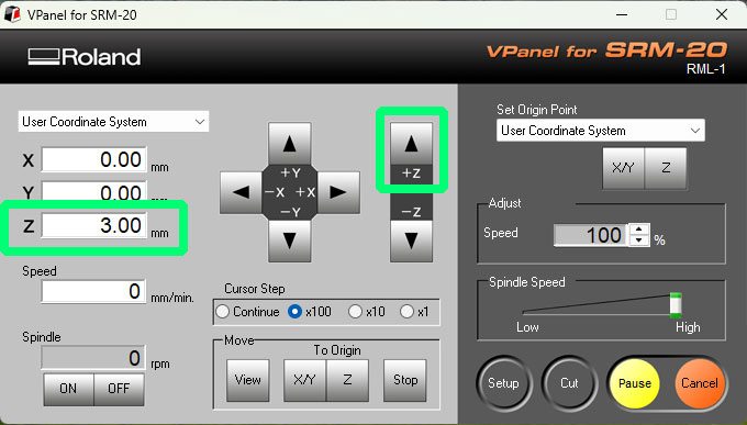
4. Raise the Z axis about 3 mm (using Cursor Step x100) before starting the job.
Milling process
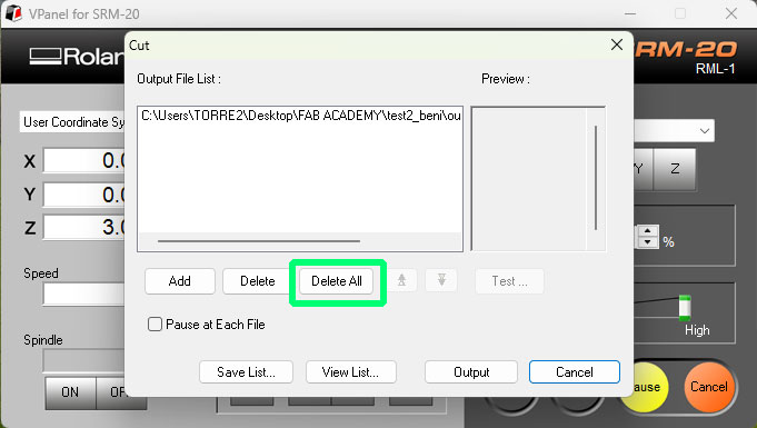
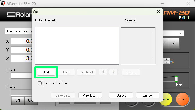
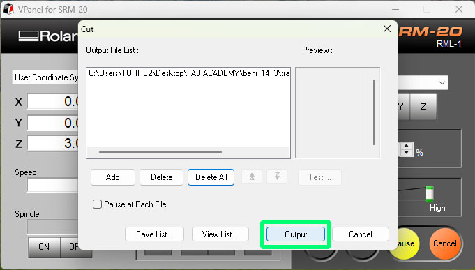
Once the origins have been configured, the next step is to send the milling file to the machine.
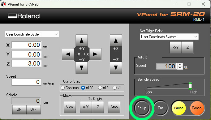
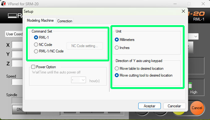
First open the Setup menu in VPanel and check that the RML-1 → Millimeters and Move cutting tool options are enabled. After confirming the configuration, continue with the job setup.
Then press the Cut button to load the milling file. Before adding a new one, delete any previous jobs using “Delete All”. Then select “Add” and load the corresponding .rml file.
For safety, start the job with the speed reduced to 20%. After pressing Output, the spindle will start rotating and the machine will begin milling the board.
During the first moments of the process, check that everything is working correctly. Once the milling operation is stable, increase the speed to 100%.
After finishing the traces, change the tool to a 0.8 mm (1/32”) end mill to perform the drilling and the outer cut. When changing the tool, it is necessary to recalibrate the Z origin, but the X and Y coordinates remain unchanged because the PCB position does not move.
Finally, repeat the loading and execution process with the remaining .rml files corresponding to the drills and the outer cut, thus completing the PCB milling process.
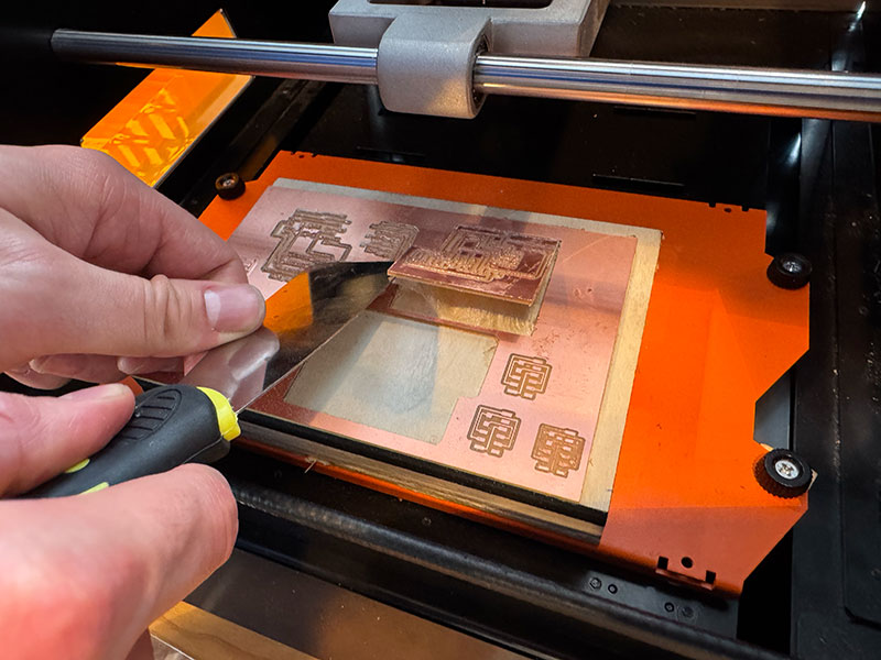
PCB cleaning and finishing
Once the milling process is finished, the next step is to clean the work area and prepare the board for use.
First vacuum the milling debris, removing the dust and small particles of material left on the surface of the machine. Then remove the PCB from the sacrificial layer by gently lifting it with a spatula, taking care not to bend the board or damage the base surface.
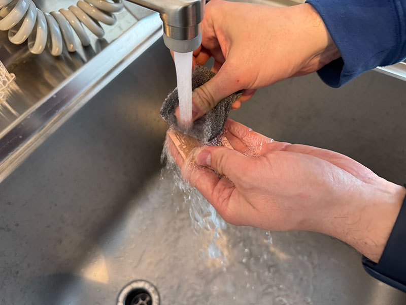
After separating the board, clean it more thoroughly using water and a metal scouring pad. This step helps remove any material that may not have been removed by the vacuum cleaner, as well as small burrs that may remain around the traces or edges after machining.
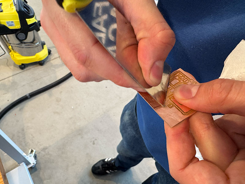
Finally, use a spatula to go over the edges of the PCB, slightly chamfering them to make them smoother. Also pass it over the front surface of the board to remove any burrs that may still remain after cleaning.
After this, the PCB will be clean, with smoother edges, and ready for the next step: component assembly.
Maintenance and good practices
- Clean the bed and the inside area after each use.
- Remove chips, dust, and adhesive residue from the base.
- Check the condition of the tools before each job.
- Do not force worn or damaged bits.
- Keep the cover and viewing area clean for better process supervision.
- Always store collets, wrenches, and bits in their proper place.
Since it is a compact and quite precise machine, it benefits greatly from basic maintenance. Nothing complicated is needed: cleanliness, order, and tool checking usually make a big difference in the final quality.
Safety rules
- Do not start the machine without the material being properly fixed.
- Do not put your hands in the work area while the spindle is moving.
- Keep the cover closed during machining whenever possible.
- Do not use the machine if the front cover is damaged or cracked.
- Do not use it in humid environments or with wet hands.
- Do not leave flammable objects or aerosols near the machine.
- Disconnect immediately if smoke, unusual smells, sparks, or abnormal behavior appear.
- Always use the correct power supply and cables in good condition.
- Closely supervise the first movements after setting a new zero or changing the tool.
Safety checklist (visual)
Recommended quick checklist before, during, and after using the Roland SRM-20 milling machine.