Week 7
Computer-Controlled Machining
Contents
Week questions/tasks
Starting Point
I can say that Computer-Controlled Machining wasn't new to me. I had seen many videos of CNC machines in operation because it's always something I've enjoyed watching, although I had never operated one and therefore didn't know the workflow or the safety considerations.
Group assignment
This week's group assignment was not only very satisfying but also very practical. It's truly a pleasure to work on group assignments with the instructors and colleagues at FabAcademy.
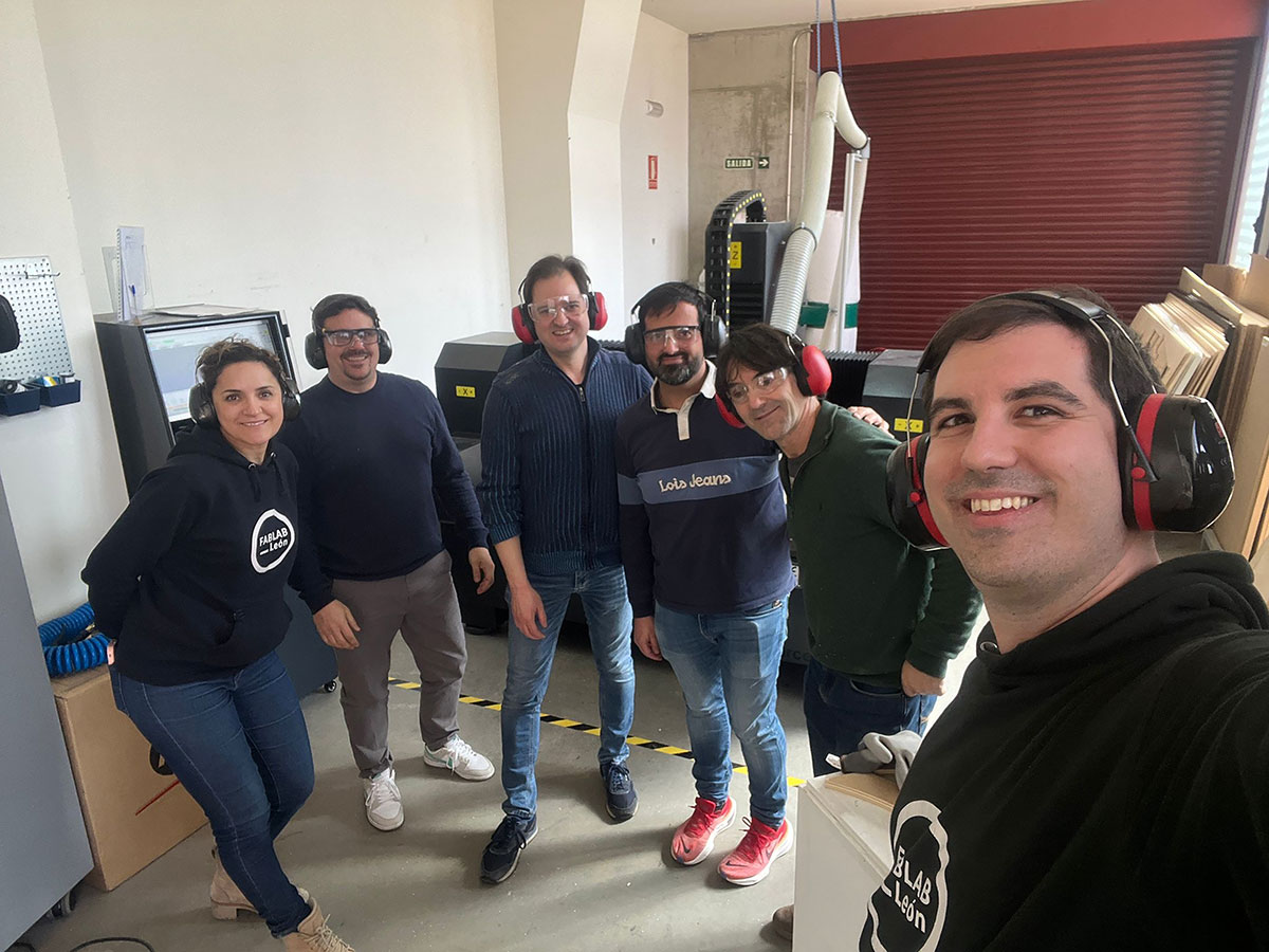
Complete your lab's safety training
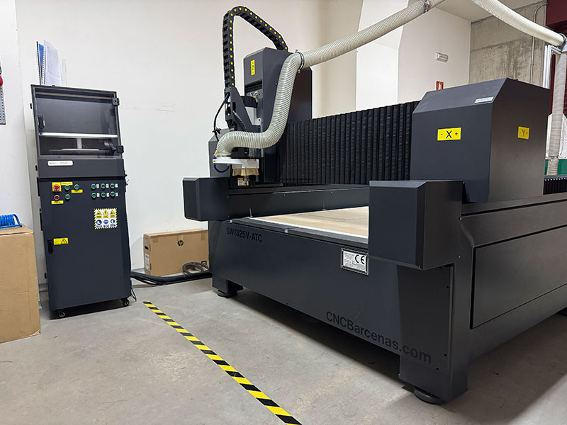
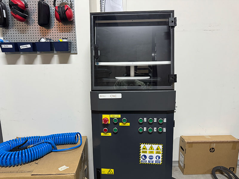
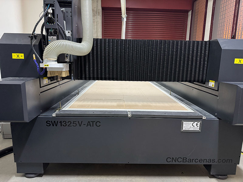
CNC specifications, Safety and Workflow: CNC Bárcenas · SW1325V-ATC - Beni's documentation
As part of the initial training, I reviewed the safe operation of the CNC Bárcenas SW1325V-ATC, including machine startup, homing procedure, material fixturing, emergency stop location, personal protective equipment, and workspace cleaning after machining. The full safety documentation can be found in the Safety section and the Safety checklist.
Test runout, alignment, fixturing, speeds, feeds, materials and toolpaths for your machine
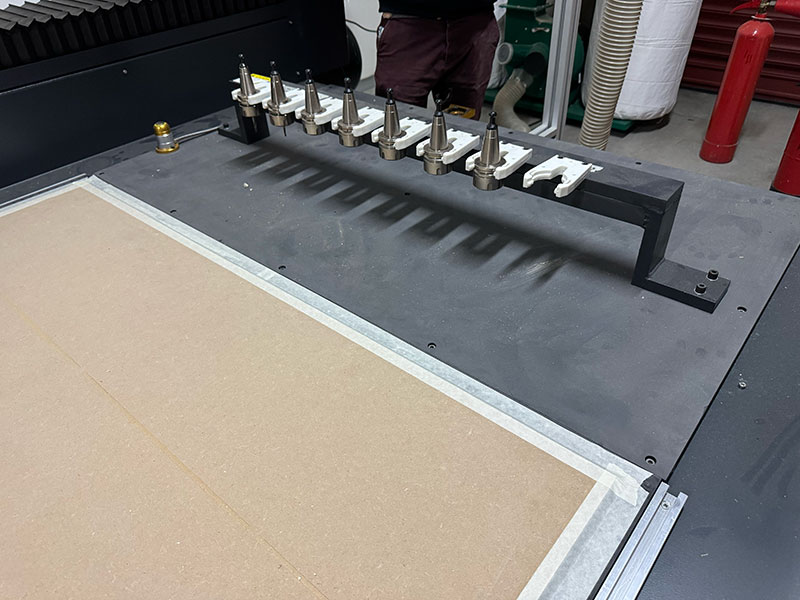
As a group we analyzed the main factors that influence machining quality on the CNC router, including tool runout, material alignment, fixturing methods, toolpath strategies, and machining parameters such as RPM, feed rate, depth of cut, and tool selection depending on the material. This work is documented in the Machining parameters section and the Runout, fixturing, alignment and toolpath strategy section.
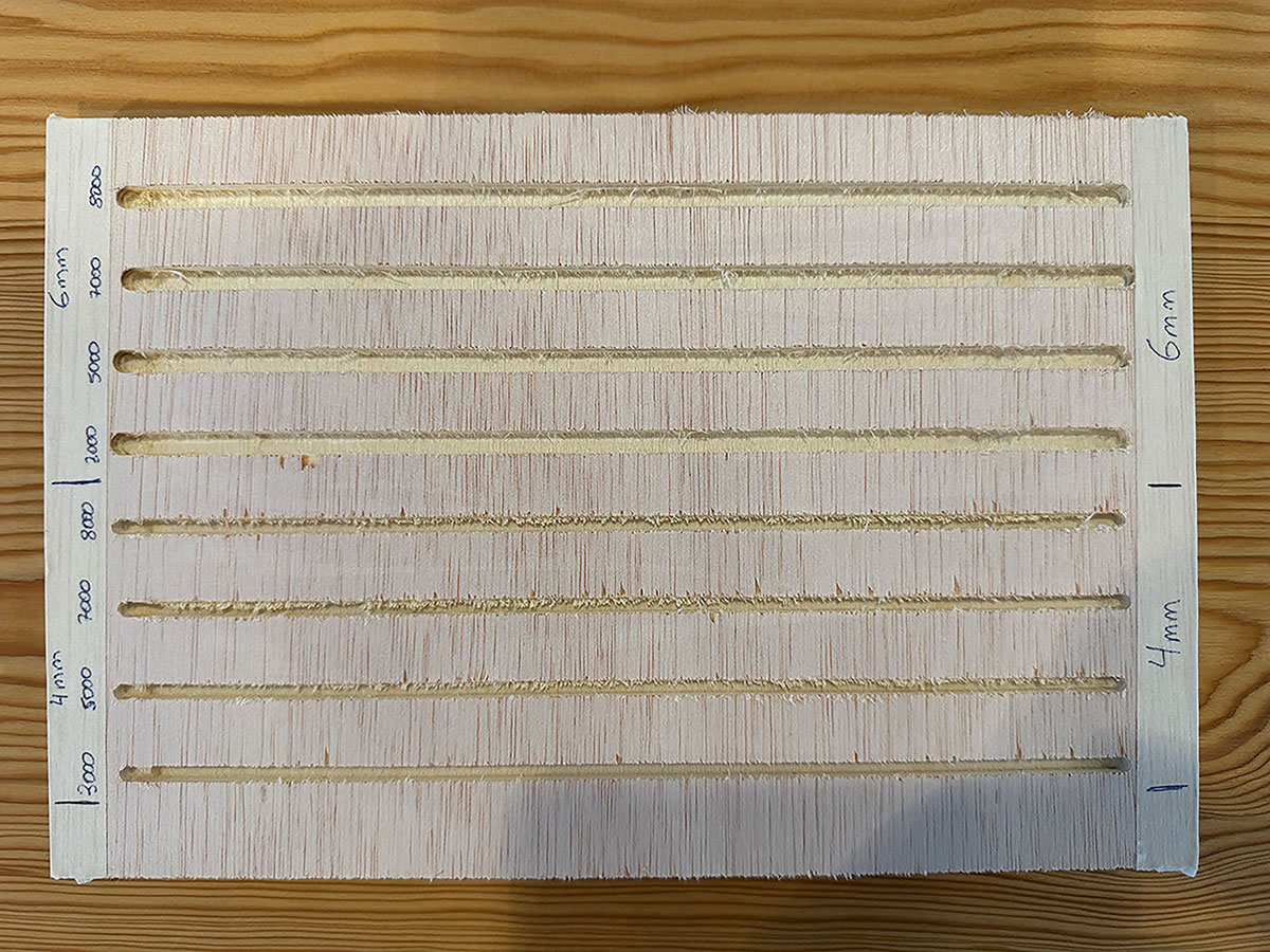
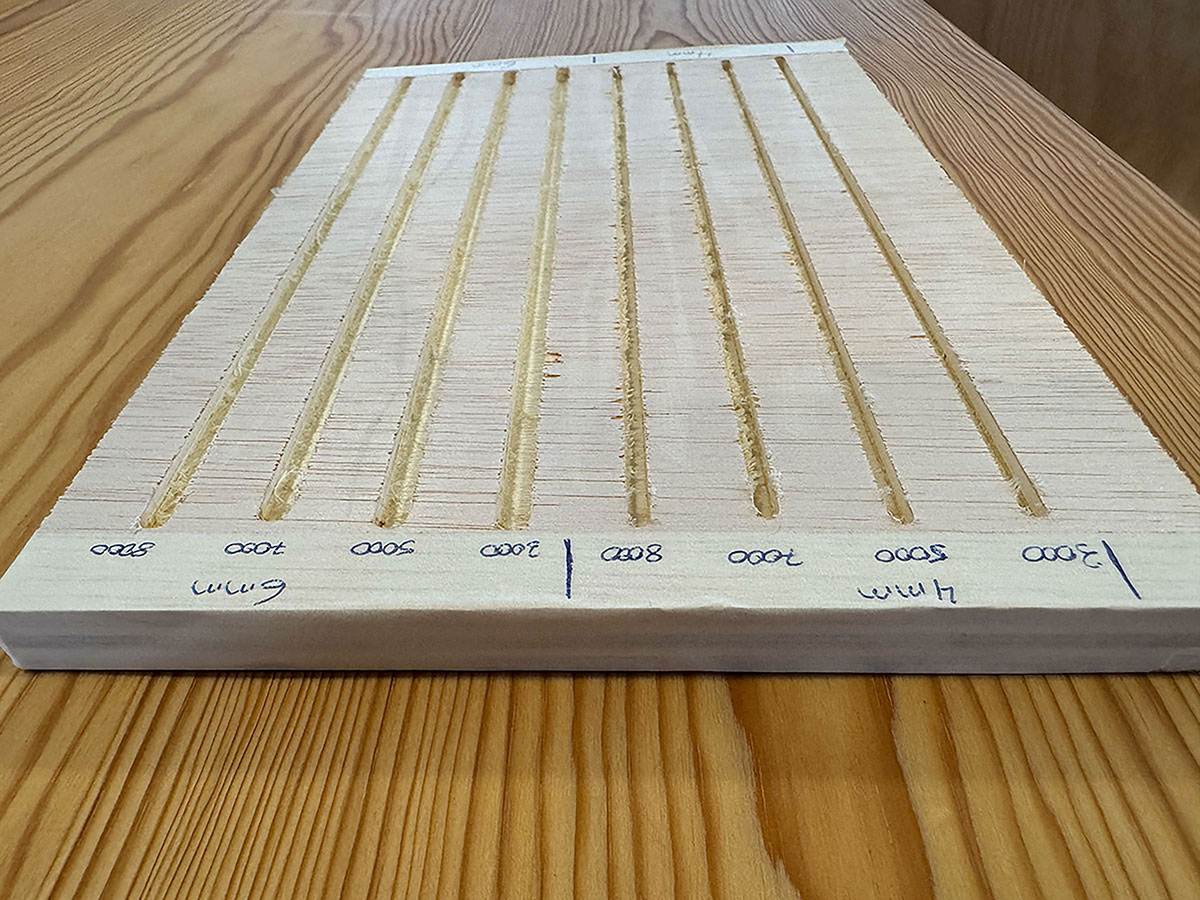
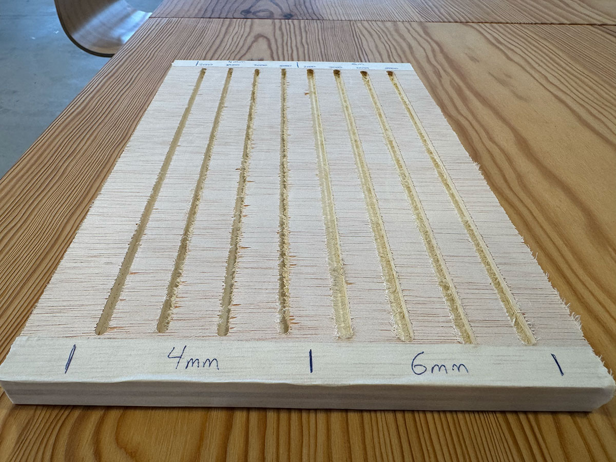
Tool specifications and milling parameter
| Tool Parameter | Value |
|---|---|
| Tool Type | End Mill |
| Diameter | 4 & 6 mm |
| Material | 15 mm Pine Plywood |
| Pass Depth | 4 mm |
| Stepover | 2.4 mm (40%) |
| Spindle Speed | 18000 rpm |
| Feed Rate | 3000, 5000, 7000 and 8000 mm/min |
Document your work on the group work page and reflect what you learned on your individual page
The general machine documentation and workflow were compiled in a dedicated reference page including specifications, compatible materials, workflow, tooling, machining parameters, and safety rules. Based on this group work, my individual page reflects what I learned about material preparation, setting the work origin, selecting end mills, adjusting machining parameters, and applying good CNC machining practices. The complete documentation can be found here: CNC Bárcenas SW1325V-ATC documentation.
Individual assignment
Make (design+mill+assemble) something big
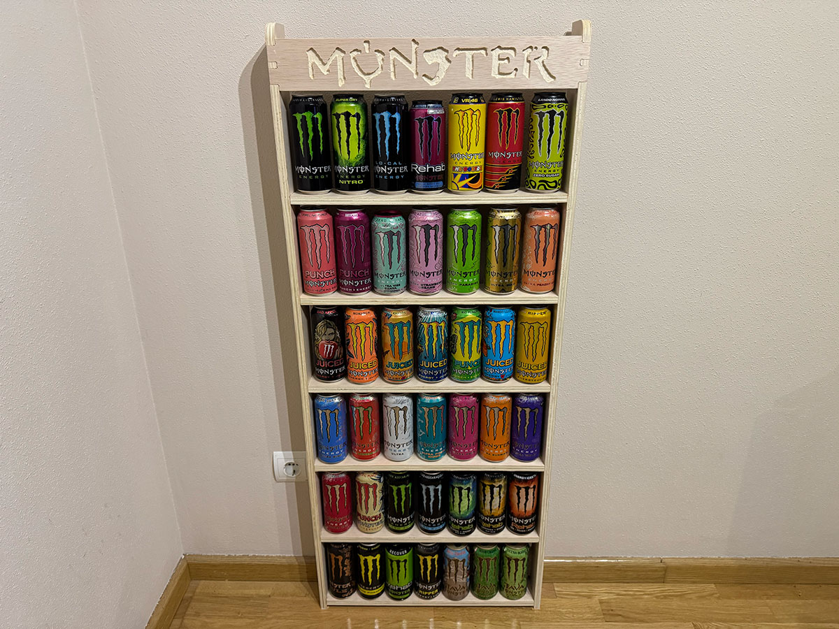
For this assignment I have decided to build a shelf to display part of my cans collection of Monster Energy drink.
Design
Parametric Design of the Shelf
To design the shelf I only needed to model two different types of parts: the vertical side panels and the horizontal shelves. In the case of the vertical pieces, both sides are exactly the same, with one simply being the mirror of the other. Because of that, it is enough to design only one of them.
I decided to include six shelves in the structure. Since all of them share the same dimensions, I only needed to design a single shelf and reuse that geometry for the rest.
In addition to the six shelves, I added two extra pieces identical to the shelves. These additional parts will help increase the structural rigidity of the furniture. One will be placed at the top front of the structure and the other at the lower rear part, helping stabilize the whole assembly.
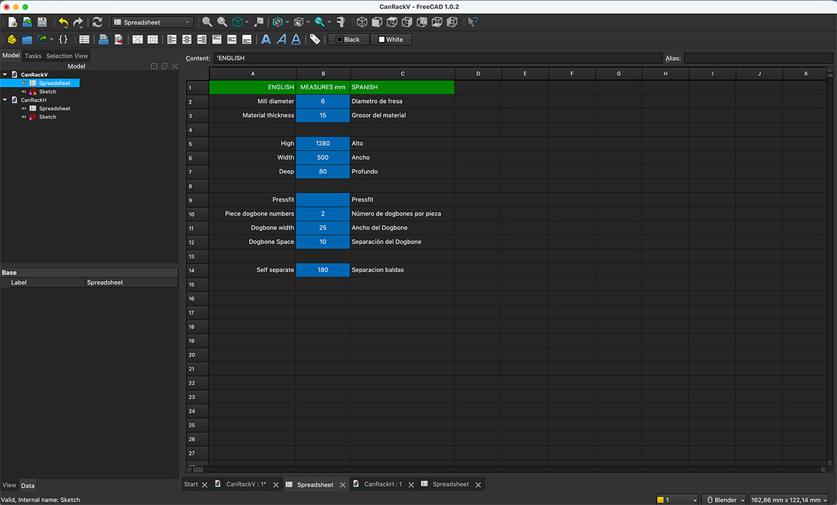
The design was created in FreeCAD using the same parametric design methodology that I already used in Week 03. The first step was creating a Spreadsheet where I defined all the parameters I would need: height, width, depth and material thickness, as well as the dimensions and spacing of the press-fit joints. I also included the tool diameter and a few additional parameters that might be useful later during the design process.
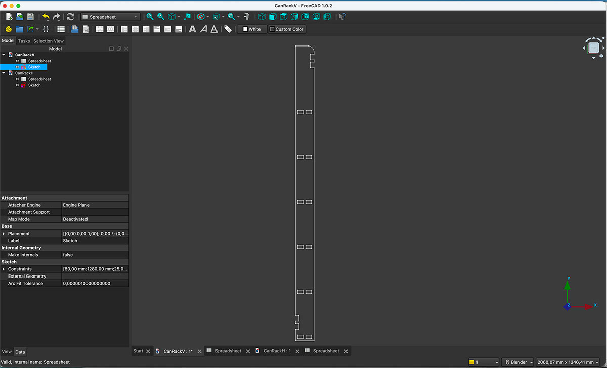
Once all the parameters were defined, I started modeling the two parts that make up the shelf.
For convenience, I created each part in a separate FreeCAD file, but both files share the same parametric values defined in the spreadsheet. This approach makes it easy to modify any dimension later if adjustments are needed.
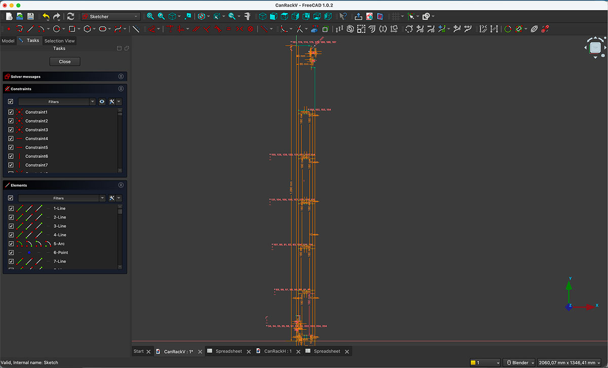
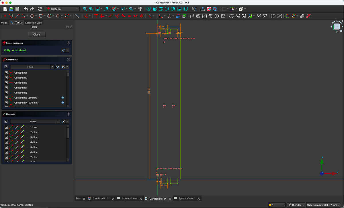
For each part, the overall dimensions are linked directly to the values defined in the parameter table. The press-fit joints were also designed using those same variables, ensuring that the entire design remains fully parametric.
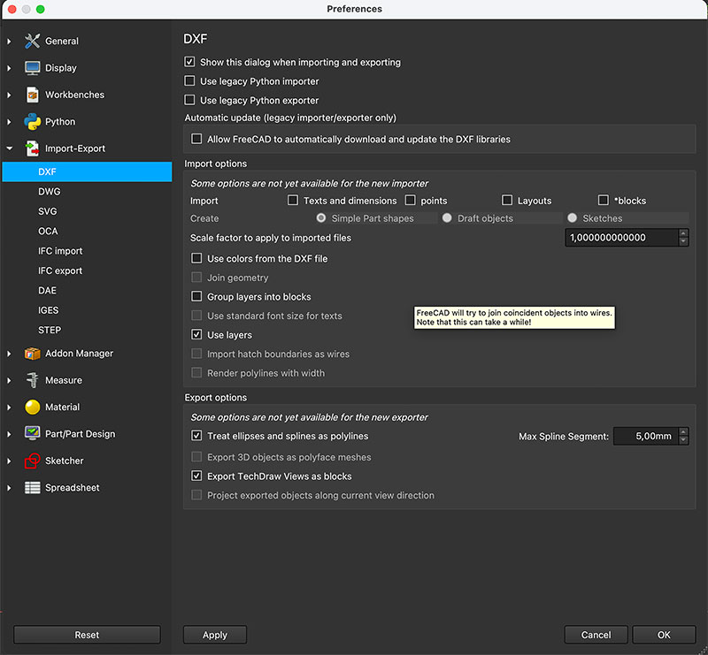
After finishing the design and verifying that all the constraints were correctly defined, I exported each part as a .DXF file, which will be used later to generate the machining toolpaths for the CNC.

Preparing the CNC Toolpaths
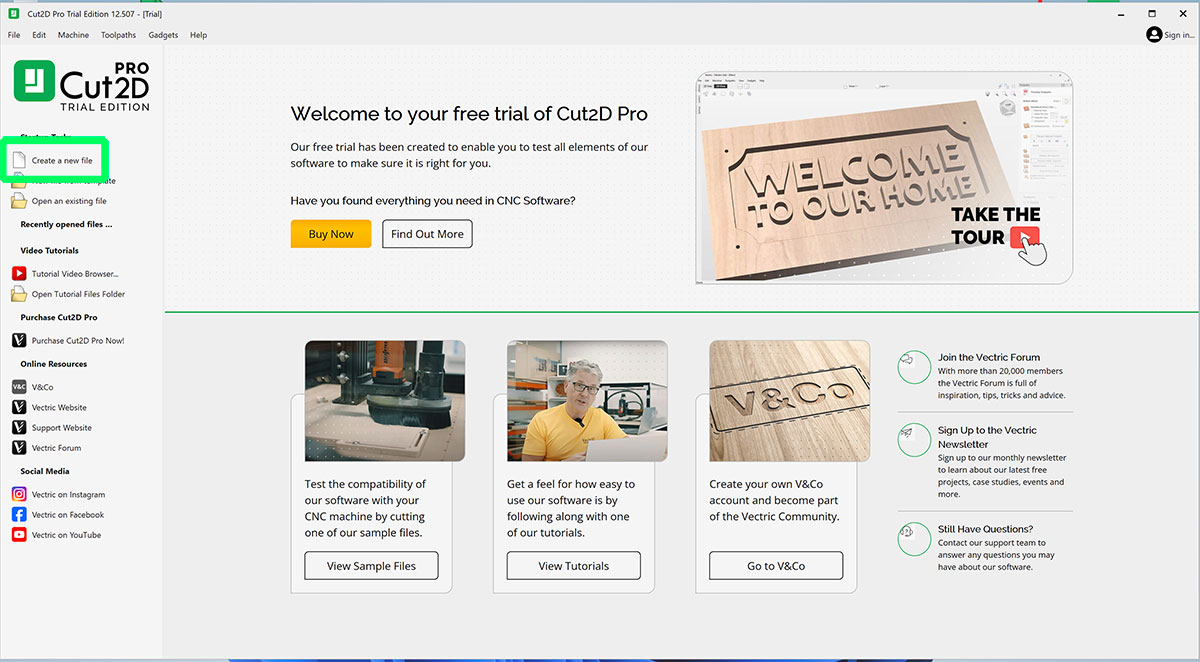
Once the design of the parts was finished, the next step was preparing the CNC machining toolpaths. For this task we used Cut2D Pro, which is the software available in our FabLab for generating toolpaths.
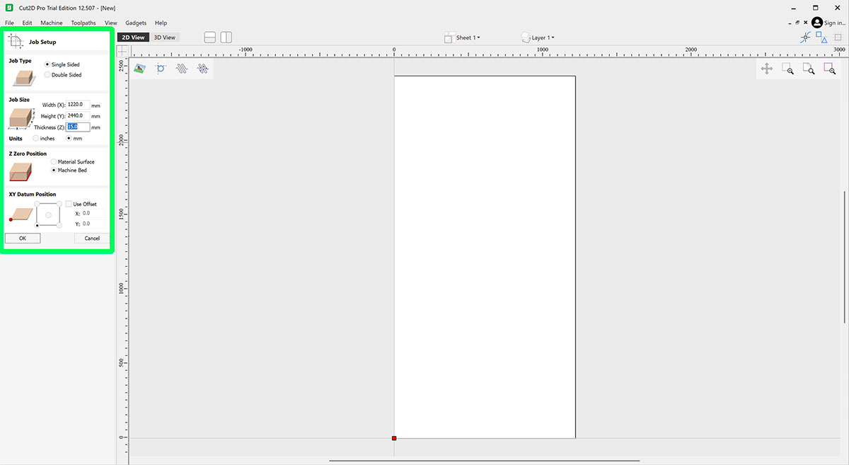
After opening the program, the first thing to do is define the size of the material we are going to use. In my case I worked with a sheet of pine plywood measuring 1220 × 2440 mm with a thickness of 15 mm, which corresponds to the standard boards available in the lab. These values define the working area inside the software.
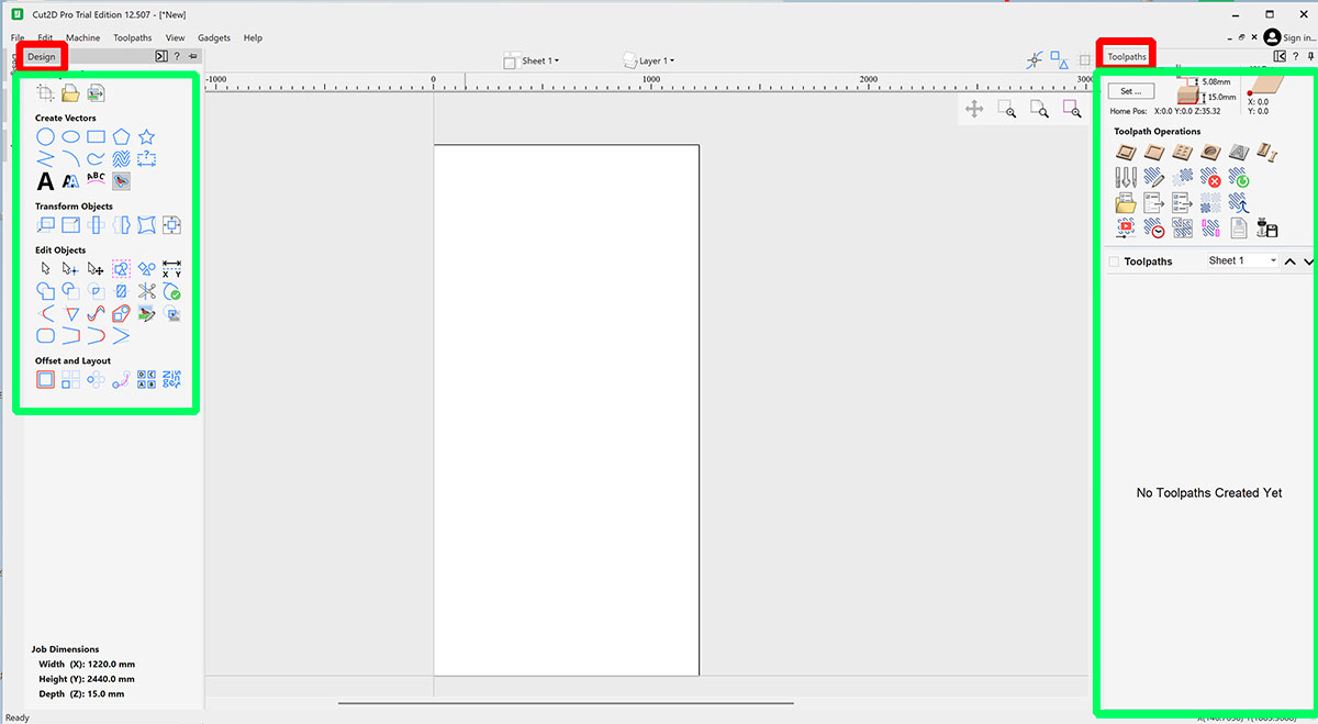
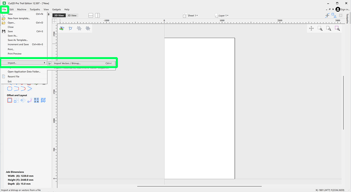
Next, I imported the parts from the .DXF files previously exported from FreeCAD.
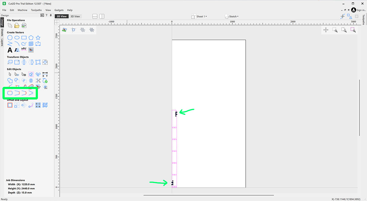
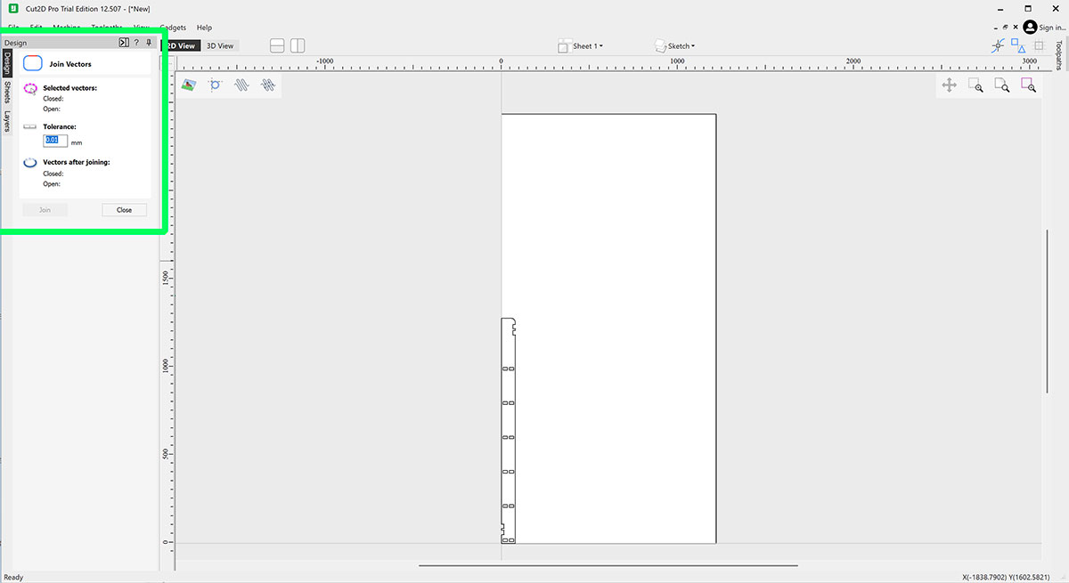
After inserting the vectors into Cut2D, it is important to verify that all geometries are properly closed. The software highlights any open vector endpoints in black, making them easy to identify. If this happens, the solution is simple: select all the vectors and use the “Close / Join Vectors” tool to connect the open segments.
This check is important before creating the machining toolpaths, since open vectors may cause errors during the toolpath calculation or result in incomplete cuts on the CNC machine.
Preparing the Layout and Toolpaths
Next, I inserted the second part into the working file and repeated the same vector check process. In this case it was also necessary to use the join vectors tool to make sure all the geometries were properly closed before continuing.
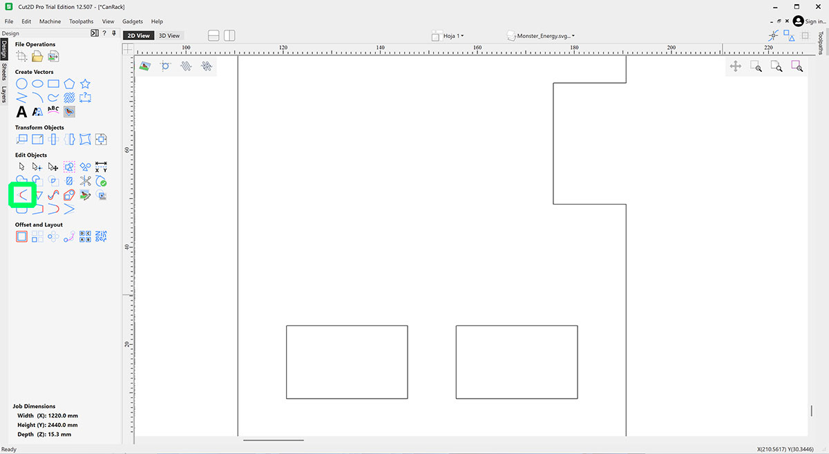
Once all vectors were closed, the next step was to create the dogbones (3mm -radius of the milling cutter-). For this I used the Fillet tool available in Cut2D. It is important that the geometries are not grouped at this stage, because dogbones need to be applied individually to each internal corner where another piece will later fit.
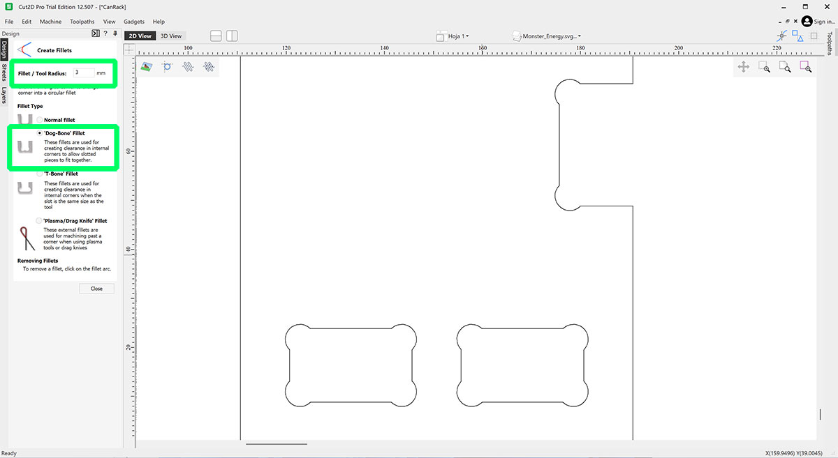
After creating all the necessary dogbones, I grouped the geometries corresponding to each part. Then I duplicated the pieces to generate the number of units required for the shelf. For the vertical sides, I used the mirror tool to obtain the symmetrical piece.
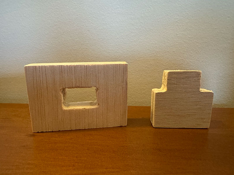
Before moving forward, I also added two small test pieces. These allow me to check the press-fit tolerance and verify that the dogbones work correctly before machining all the parts from the board.
Once the layout of all parts on the board was ready, I moved on to creating the machining toolpaths.
It is generally recommended to create the toolpaths following this order:
- Pocket toolpaths
- Inside profile cuts
- Outside profile cuts
Following this order helps ensure a more efficient machining process and prevents parts from moving while they are still attached to the board.
I select each of the pieces that will follow the same path and create the path in the right-hand column. I create each of the three paths (Pocket → Inside → Outside).
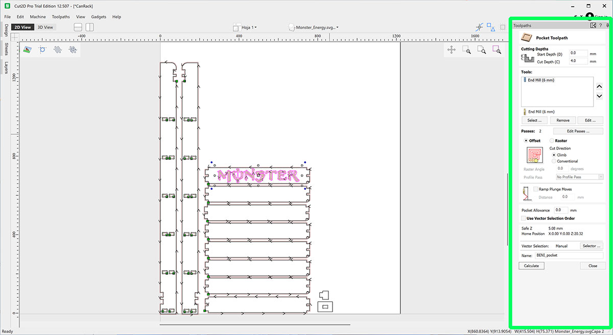
In my case, I used the following parameters:
Toolpaths
| Parameter | Pocket Toolpath | Inside Profile | Outside Profile |
|---|---|---|---|
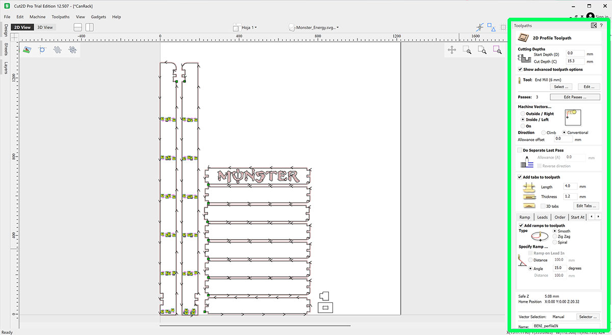
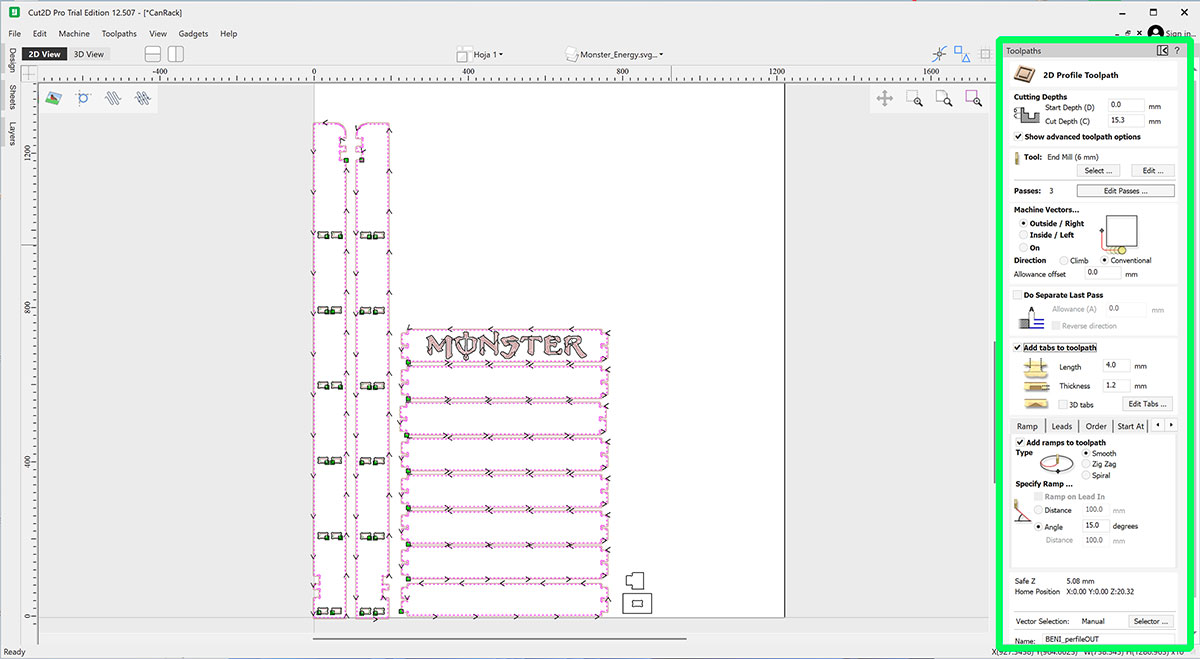
| Start Depth | 0.0 mm | 0.0 mm | 0.0 mm |
| Cut Depth | 4.0 mm | 15.3 mm | 15.3 mm |
| Passes | 1 | 3 | 3 |
| Machining Type | Profile | Profile | |
| Vector Side | Offset | Inside / Left | Outside / Right |
| Cut Direction | Climb | Climb | Conventional |
| Add Tabs | No | Yes | Yes |
| Tab Length | — | 4.0 mm | 4.0 mm |
| Tab Thickness | — | 1.2 mm | 1.2 mm |
| Add Ramps | No | Yes | Yes |
| Ramp Type | — | Smooth | Smooth |
| Ramp Setting | — | Angle: 15° | Angle: 15° |
Tool specifications and milling parameter
| Tool Parameter | Value |
|---|---|
| Tool Type | End Mill |
| Diameter | 6 mm |
| Flutes | 2 |
| Material | 15 mm Pine Plywood |
| Pass Depth | 2 mm |
| Stepover | 2.4 mm (40%) |
| Spindle Speed | 10000 rpm |
| Feed Rate | 5000 mm/min |
| Plunge Rate | 1000 mm/min |
| Chip Load | 0.25 mm |
| Tool Number | 8 |
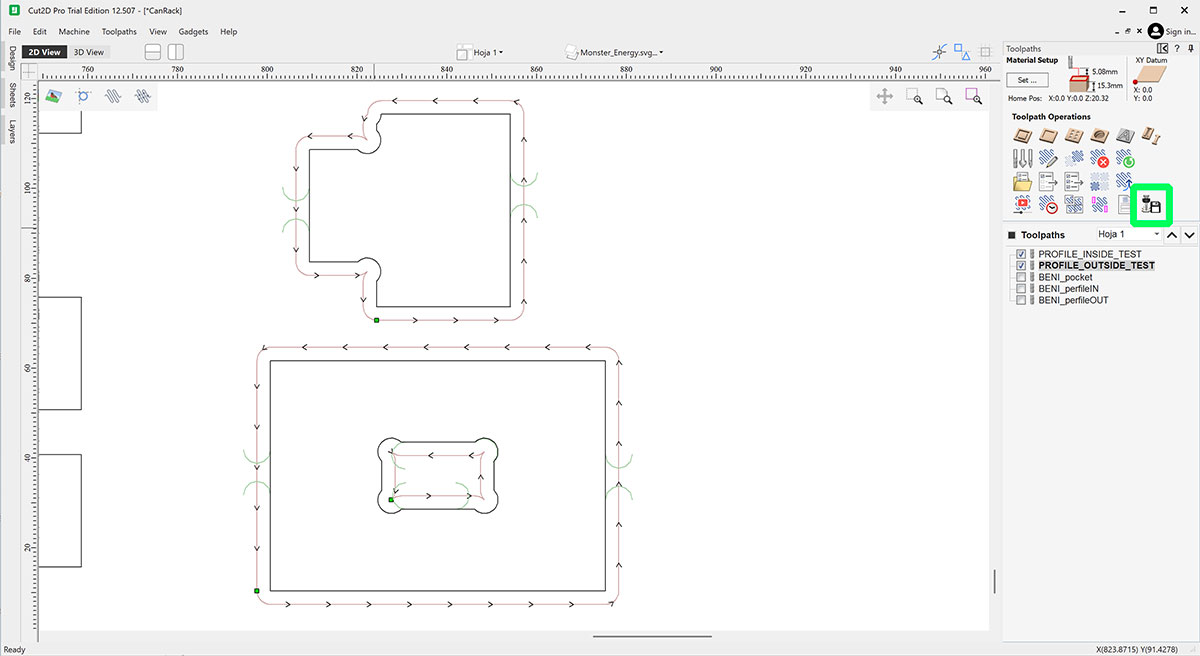
Exporting the Toolpaths
In my case, I created a total of five machining toolpaths. Two of them were intended for a press-fit test, while the other three were used to machine the final shelf parts. This way, I could first mill the test pieces and check whether the joints needed any adjustment before machining all the final parts.
This step is important because the press-fit tolerance can vary slightly depending on the material, the end mill, or even small machine deviations. By making a quick test first, I could verify whether the fit was correct or if I needed to adjust the slot dimensions before continuing with the full job.
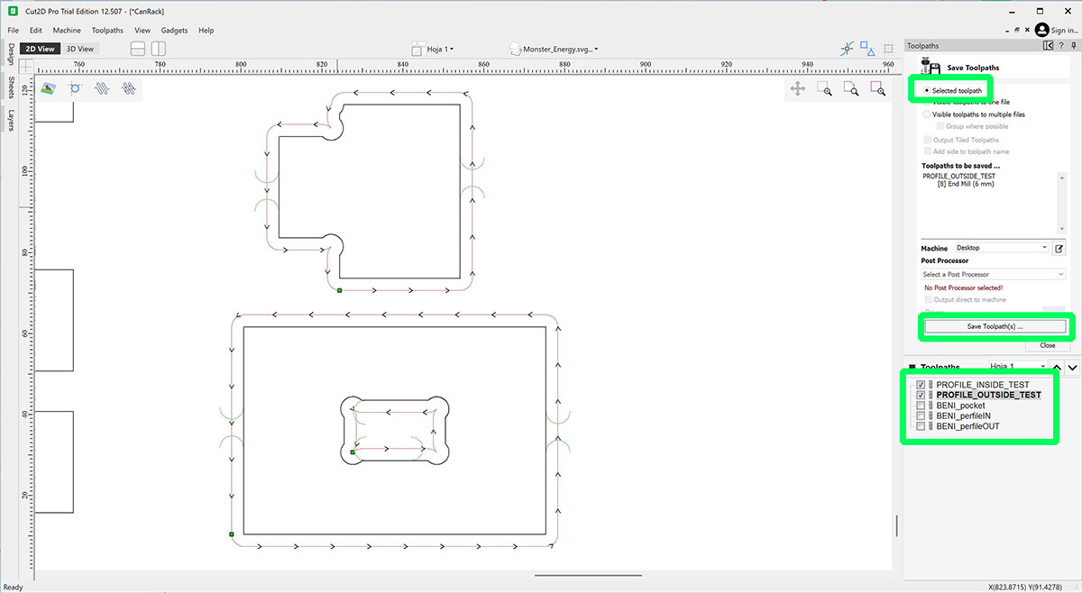
To export the toolpaths as G-code files, I selected the ones I wanted to save from the list of toolpaths created in the project. In this first case, I selected only the two test toolpaths and clicked the “Save Toolpath” button.
Before saving, it is important to make sure that only the desired toolpaths are selected and that the “Selected toolpath” option is enabled. This ensures that the software exports only the chosen toolpaths.
The toolpaths are exported in the same order in which they appear in the list. This order can be changed by moving them within the panel, although in general it is best to keep the logical machining sequence: Pocket → Inside → Outside.
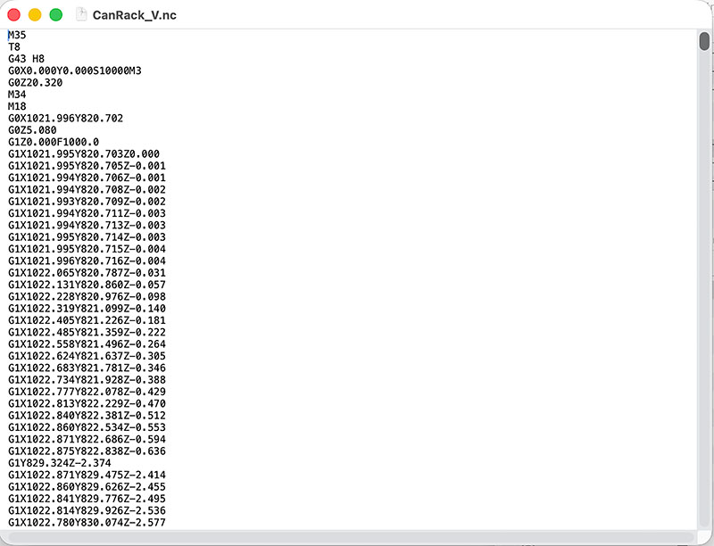
Once everything was checked, I clicked “Save Toolpath(s)” to generate the G-code file (.nc G-code file format).
After that, I repeated exactly the same process to export the three toolpaths corresponding to the final shelf parts.
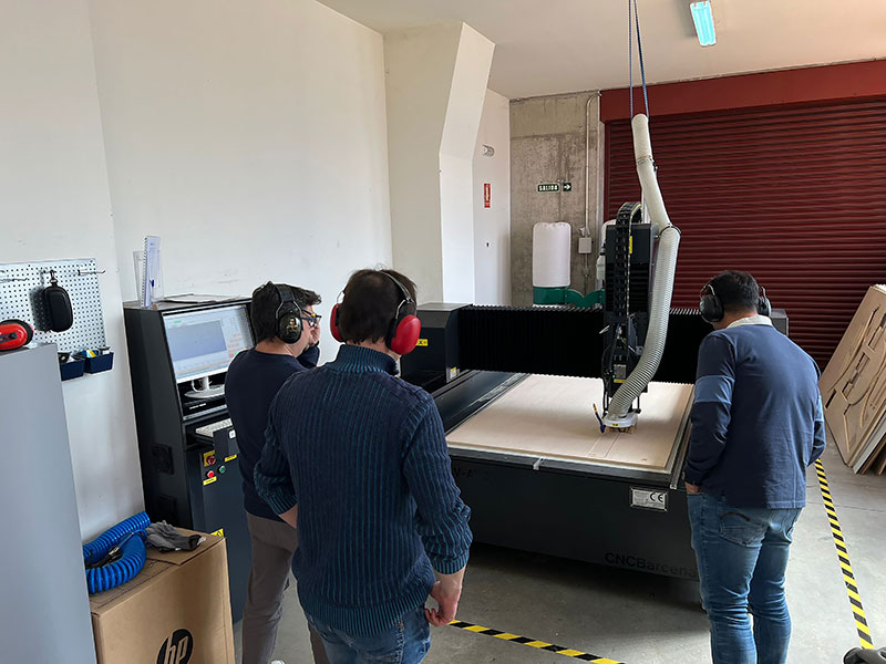
Milling on the CNC
Remember, first, make sure you know the CNC perfectly (safety, operation, ...): CNC Bárcenas · SW1325V-ATC - Beni's documentation
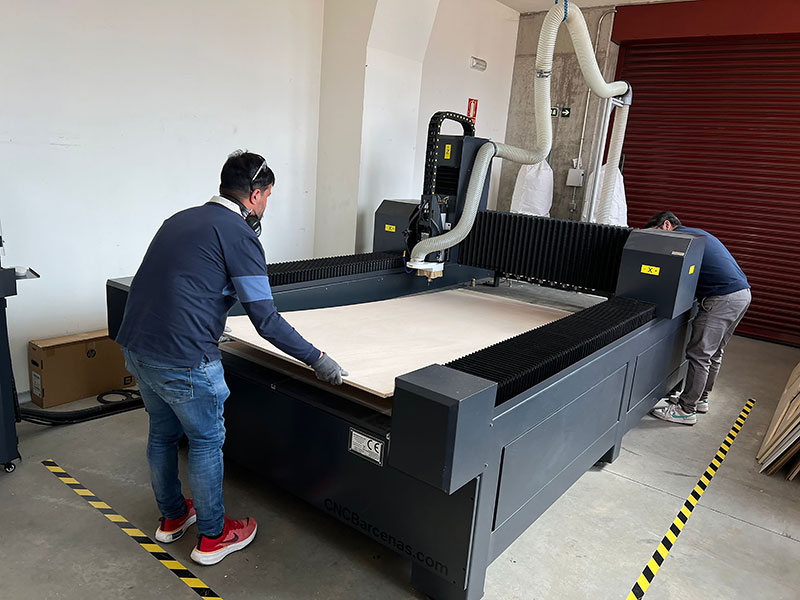
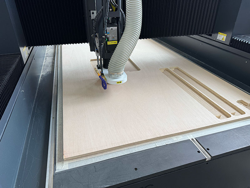
Once the G-code toolpaths had been exported from Cut2D, the next step was to prepare the machine for machining. First, we placed the material board on the CNC, using supports or stops if necessary to position it correctly. Then we switched on both the CNC and the computer connected to the machine.
Before starting any operation, it is important to follow the safety rules and the usual workflow for this machine. The full machine workflow and safety recommendations are documented on the machine page: CNC workflow and safety instructions.
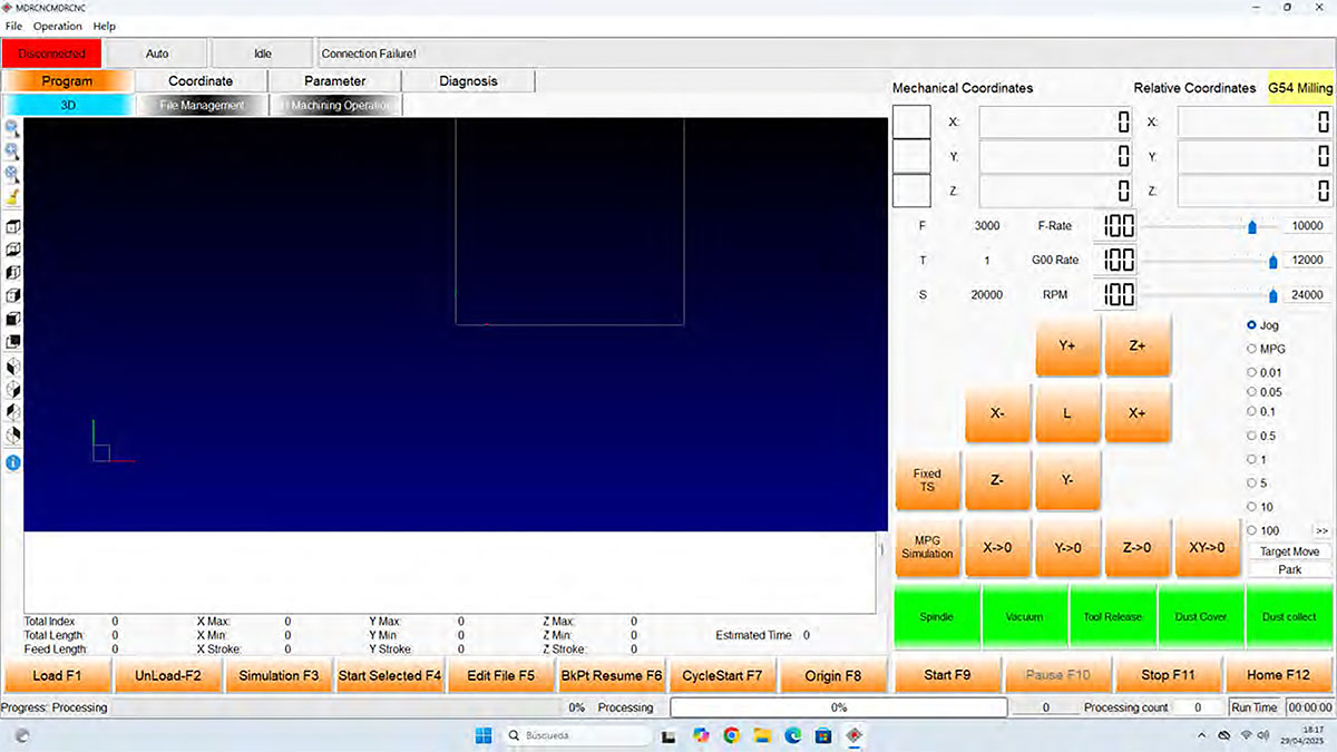
Machine initialization
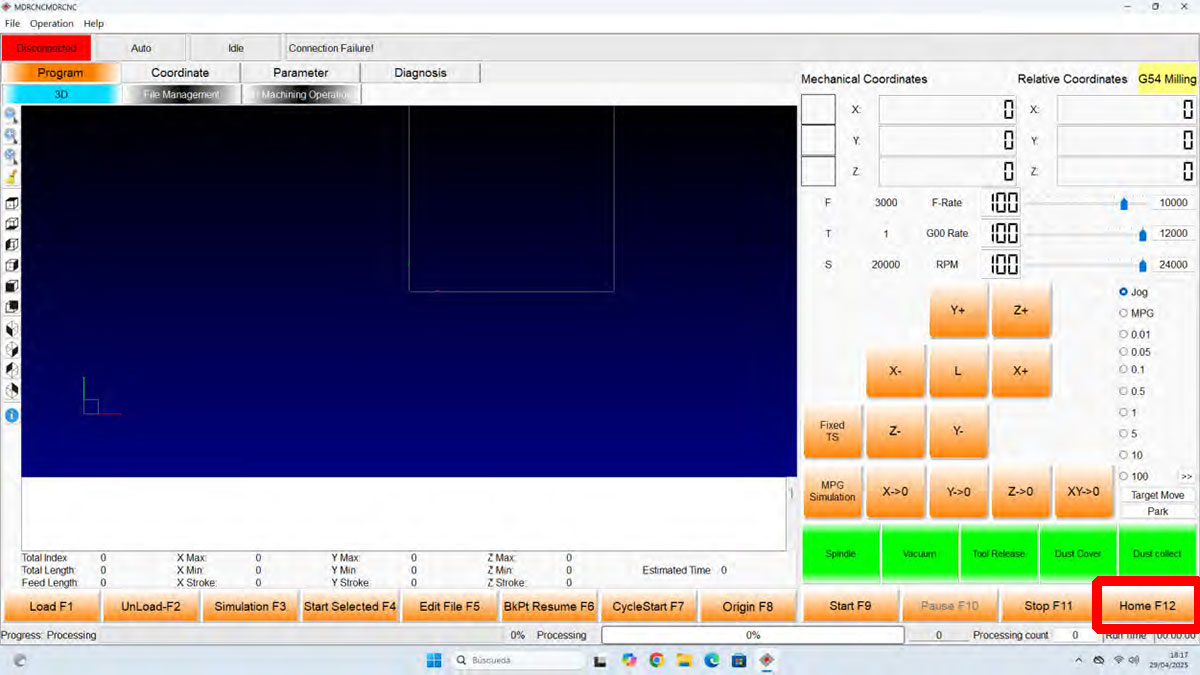
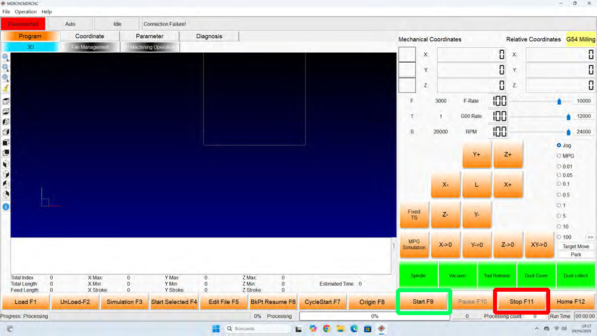
To control the machine we used the MC CNC Router software. When the program connects to the CNC, it usually asks to move the machine to the Home position. At that point, we simply press “OK” and wait for the spindle to move automatically to its reference position.
If for any reason this does not happen automatically, the same operation can be done manually by pressing the Home button in the software.
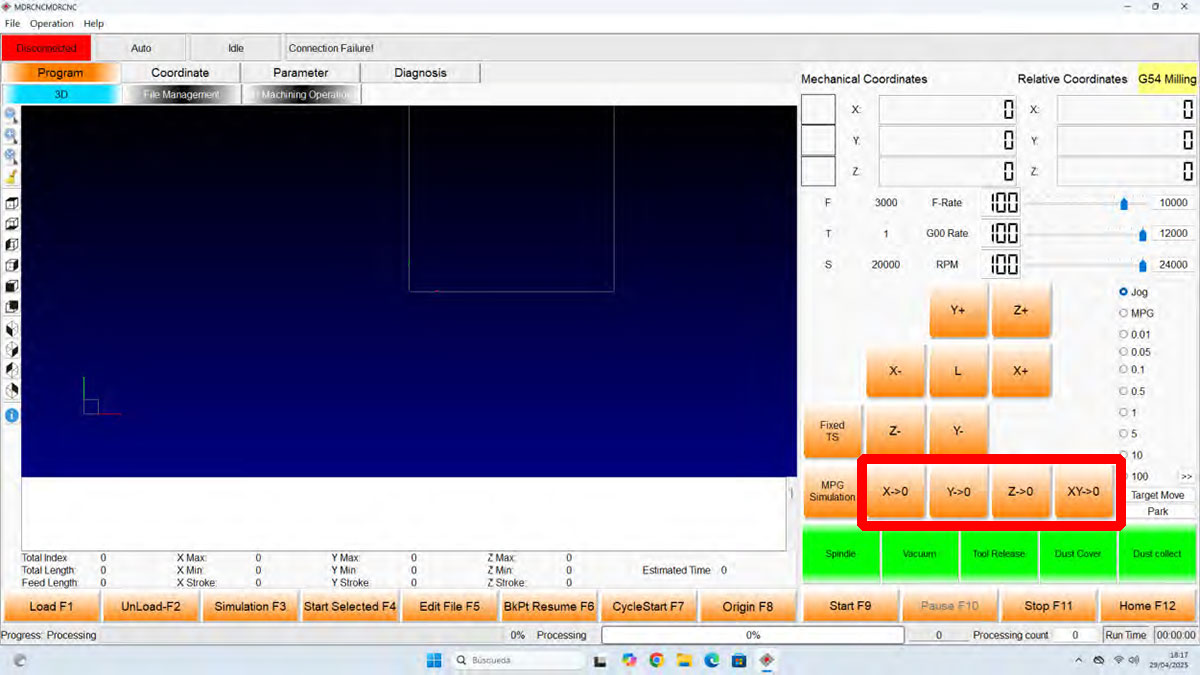
Once the machine is at its reference point, the next step is to define the work origin (0,0,0) for the X, Y and Z axes. For this I used either the movement controls in the software or the Jog/Shuttle, which makes it possible to move the spindle manually along all three axes.
At this stage it is important to make sure the origin is correctly defined and that the toolpaths fit inside the available material. This becomes especially important when the origin is not placed at the bottom-left corner of the board, for example when trying to reuse an empty area from a previously used panel.
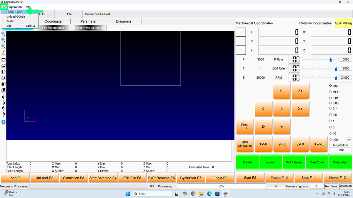
Loading and checking the G-code
Once the three axes had been set, I loaded the corresponding G-code file using File → Load GCode. At this stage I loaded only the two toolpaths for the press-fit test.
Although the CNC software also allows importing .DXF files and other formats, in this case it was much more practical to prepare all toolpaths, tools and machining parameters beforehand in Cut2D. This leaves the CNC software only for machine execution, which simplifies the process considerably.
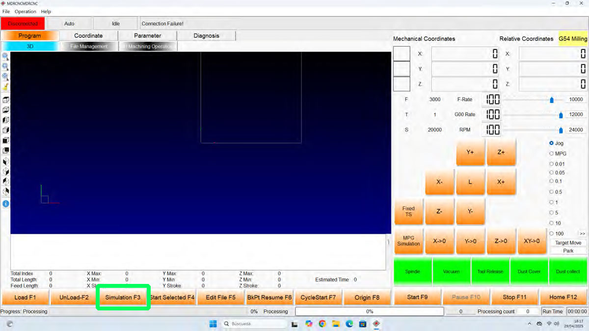
With the file loaded and the origin already defined, I used the “Simulate” button to visualize the toolpaths that were about to be executed. This makes it possible to verify once again that the loaded file is the correct one and that the machining area matches the actual position of the board.
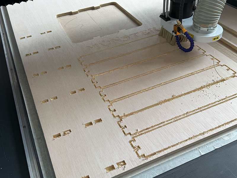
Milling process
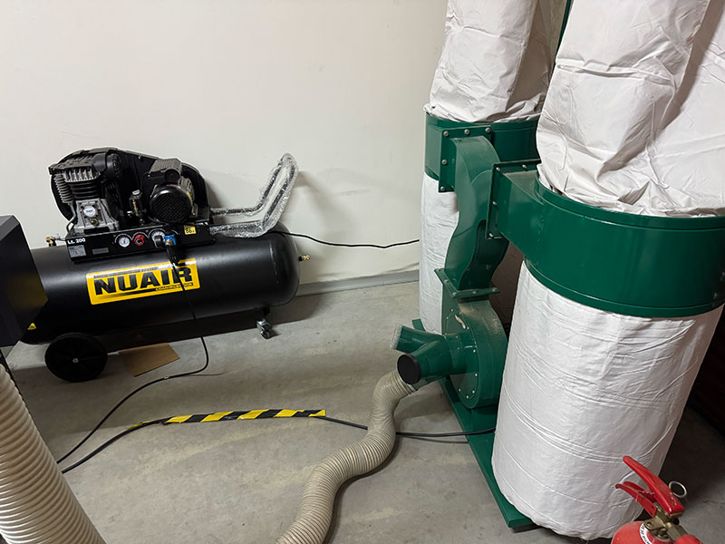
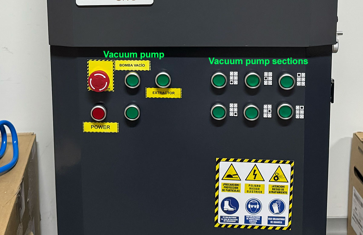
Before starting the cut, I switched on the vacuum pump, enabling the necessary zones (1 to 6) to hold the board firmly in place. I also switched on the Extraction system and checked that the material was properly fixed and did not move.
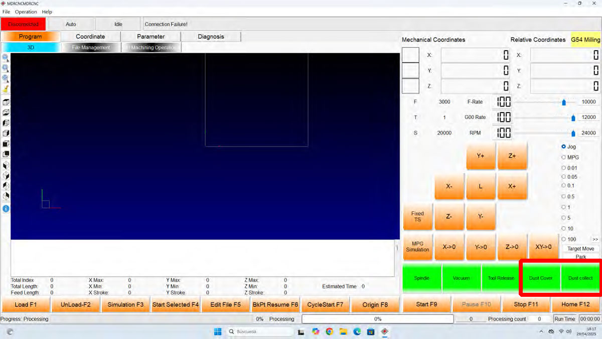
After that, I activated the dust cover & dust collect, and finally pressed START to begin the machining process.
During the entire operation it is important to continuously supervise the machine and always keep the STOP button or the emergency stop within easy reach, in case the process needs to be interrupted immediately.
Checking the press-fit
Once the test toolpaths were finished, I moved the spindle to a safe area so I could remove the parts comfortably, and then switched off the vacuum pump. After that I removed the test pieces from the board and cleaned any remaining debris if necessary.
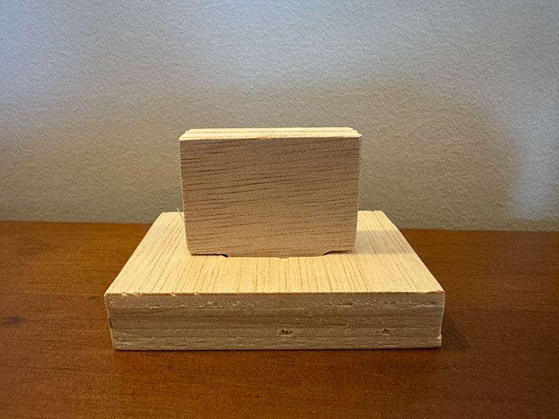
With the two test pieces machined, I checked the press-fit joint between them. In this case the fit was correct, so there was no need to modify the slot dimensions before machining the final parts.
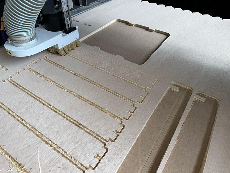
Milling the final parts
Once the fit had been verified, I repeated the same process, this time loading the toolpaths for the final shelf parts, and proceeded to machine them.
High quality video available on my YouTube channel ↗️.
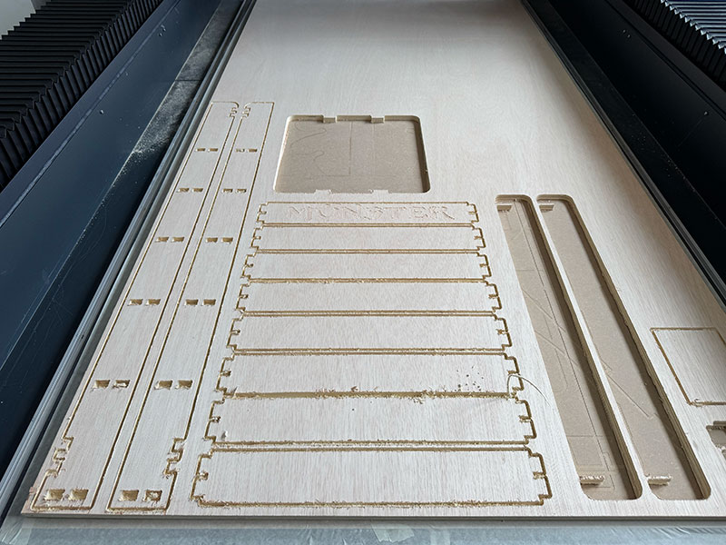
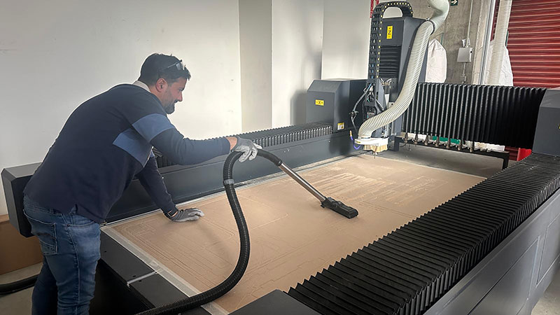
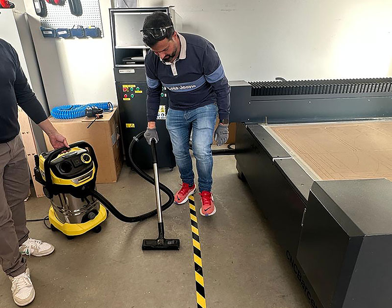
Cleaning and finishing up
When all the parts were finished, I removed the remaining material and cleaned the work area. I vacuumed the leftover chips and dust both from the CNC bed and from the floor, leaving the area clean and ready for the next use.
Assemble
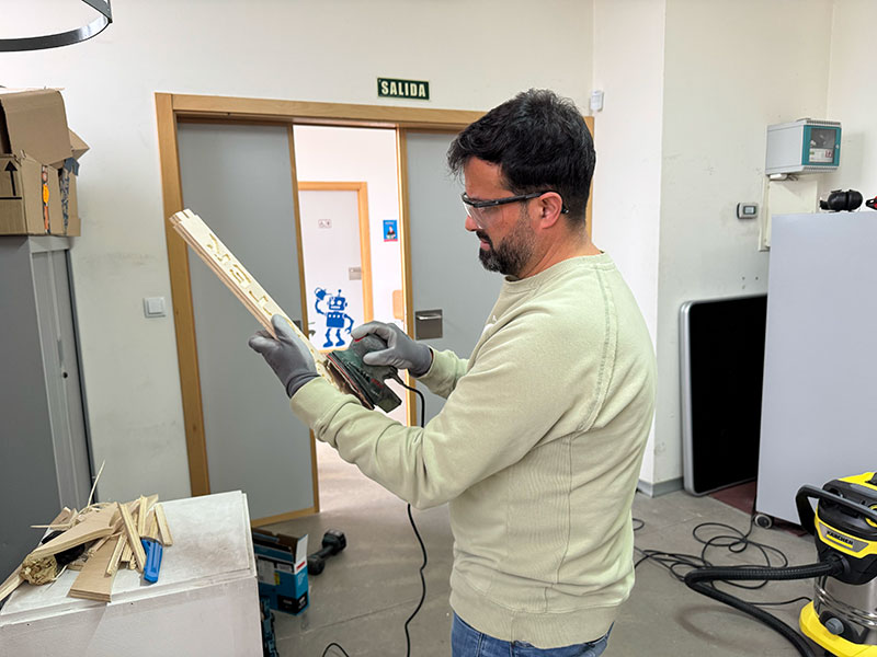
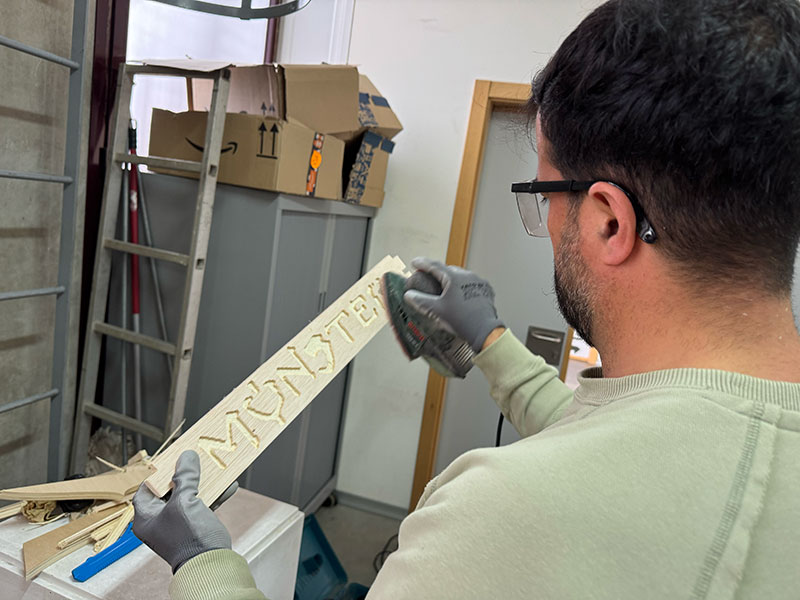
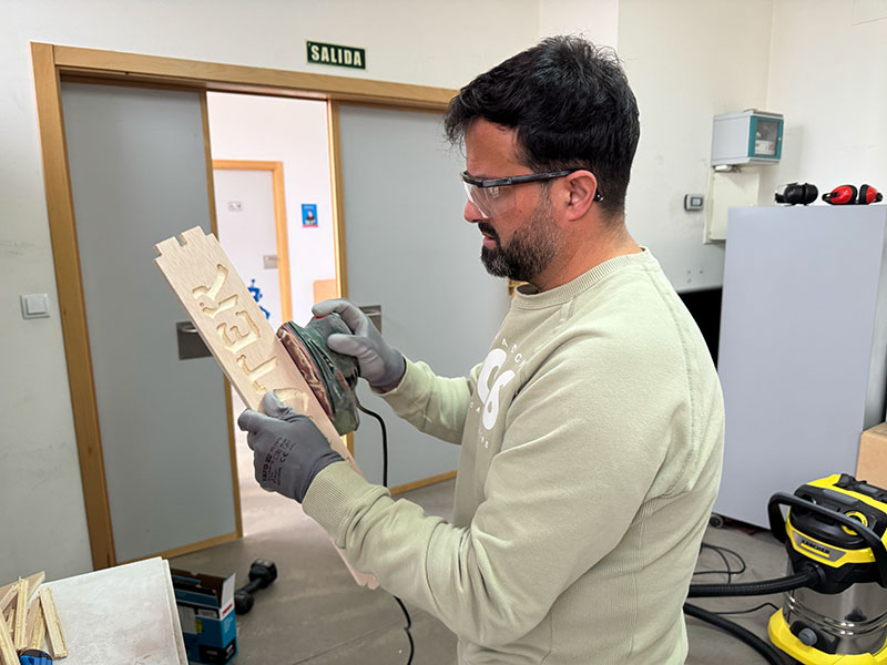
Once all the parts had been cut, the next step was to prepare them for assembly. This meant sanding them and removing the small burrs left on the wood after machining. This step was important not only for aesthetics, but also for safety, since these small splinters could be uncomfortable to handle or even get stuck in the skin.
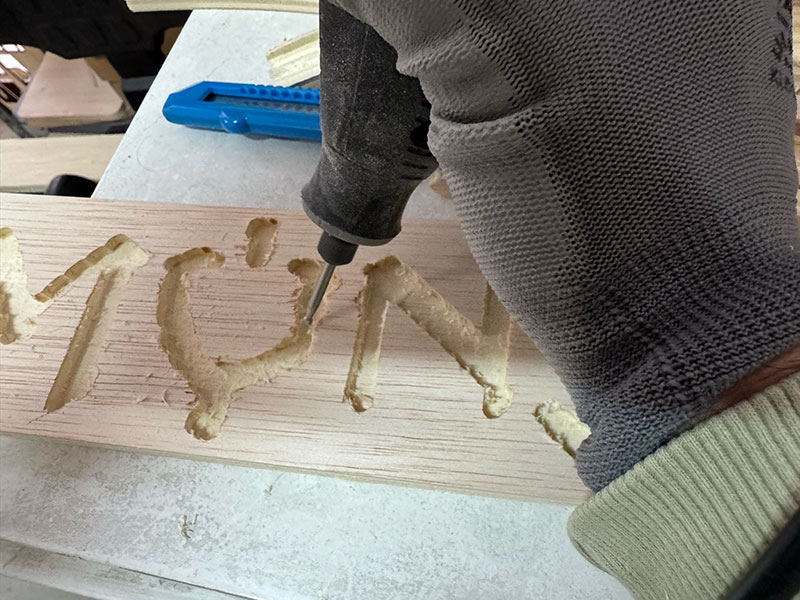
In the case of the Monster logo pocket, sanding was not enough on its own, so I also used a Dremel to clean up the inside and improve the final finish in some areas where a bit of material remained.
Once all the parts were ready, I moved on to the assembly process.
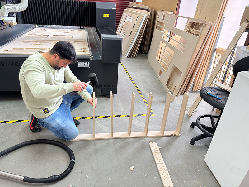
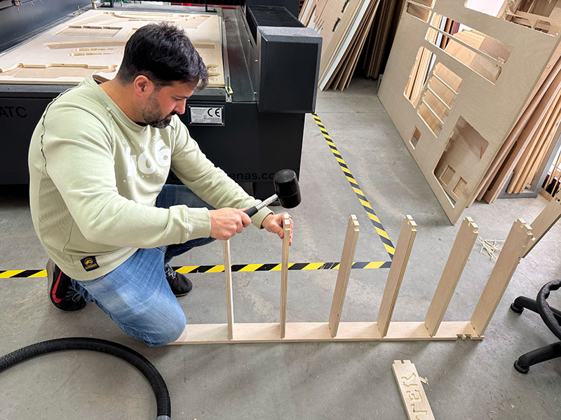
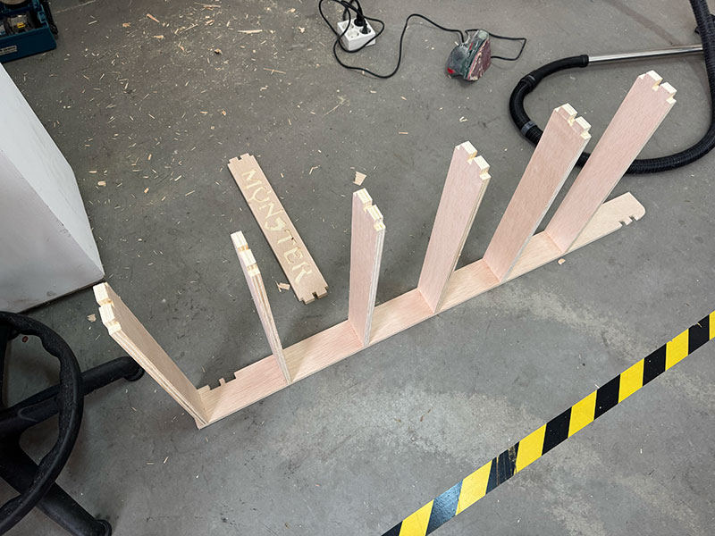
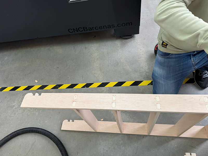
I started by placing one of the vertical side panels on the floor and then inserted all the horizontal pieces, which form the shelves, into that first side.
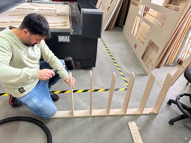
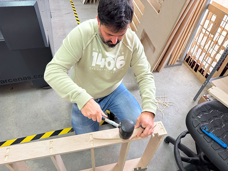
To adjust the joints properly, I used a rubber mallet together with a sacrificial wooden block. This allowed me to apply force without damaging the parts. In this way I assembled each joint while checking that the press-fit behaved as expected.
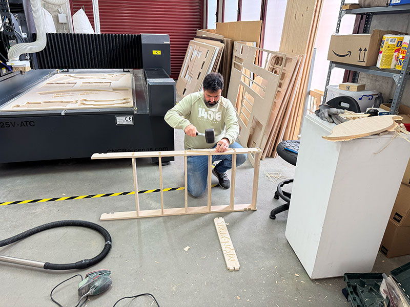
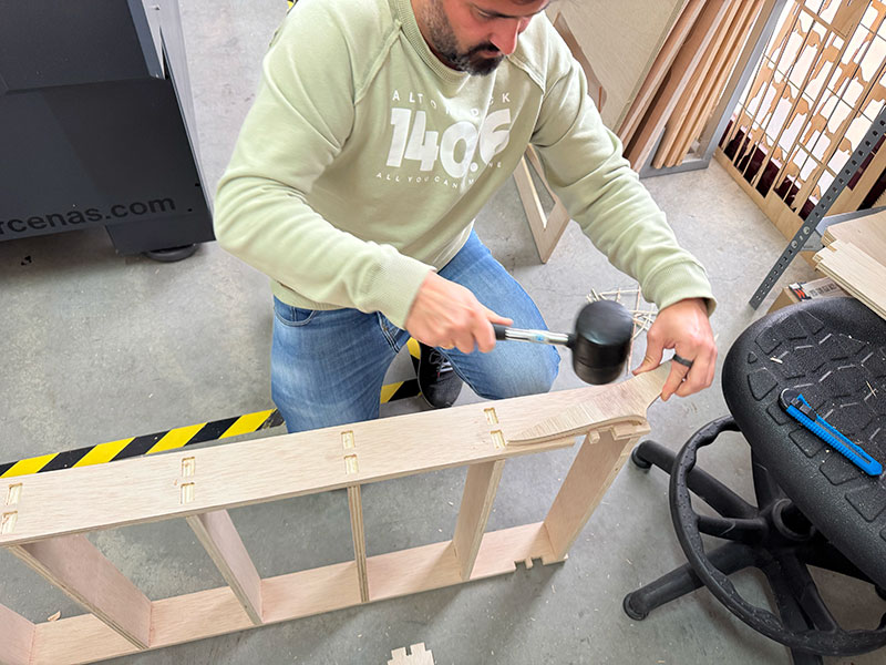
Once all the shelves were inserted into the first side panel, I continued with the second vertical piece. I first aligned each joint by hand and then finished adjusting them using the sacrificial block and the rubber mallet again.
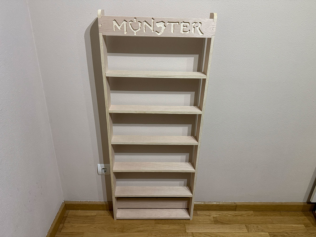
Finally, I assembled the two additional parts that help stiffen the structure: the front piece with the logo and the rear piece, which lock the whole set together.
And this was the final result of the shelf.
Improvements for the next version
- Widen the base for better floor support
- Cut a recess in the back for the baseboard so the shelf can sit flush against the wall
- Add wall brackets
- Enclose the front with acrylic
Problems & Solutions
It's important not to skip any of the safety or operational steps because, in addition to causing material and personal damage, the final result may not be correct.
In my case, while processing one of the pieces, I forgot to connect the vacuum pump, so I realized it immediately because the material started to move. Upon realizing this, I pressed the emergency stop button to stop the machine. Nothing happened other than material loss, but I realized it could have been much worse. I made sure everything was OK, set a new XYZ = 0, and processed the job again correctly.
Solution: It is essential to follow the safety and operating instructions for each machine.
Final reflection
This week has been a great learning experience, but also included some challenging moments, especially with the FreeCAD design, where I struggled to design the parts due to the constraints. For my final project, using a CNC machine is crucial, as I intend to use it to create the parts or structure of my PinSoccBall.
Original code files for this documentation
Files for download
- Vertical CanRack (FreeCAD - CanRackV.FCStd) FCStd · 166 Kb
- Vertical CanRack (CanRackH_Sketch.dxf) DXF · 16 Kb
- Horizontal CanRack (FreeCAD - CanRackH.FCStd) FCStd · 148 Kb
- Horizontal CanRack (CanRackV_Sketch.dxf) DXF · 8 Kb
- CanRack (Cut2DPro - CanRack.crv) CRV · 5,2 Mb
- CanRack (G-Code file - CanRackGCode.nc) NC · 0,8 Mb
Credits
I would like to thank the instructors Nuria ↗️, Pablo ↗️, and Adrián ↗️ for their guidance and support throughout this assignment.
Also thanks to Javier ↗️ (FabLab Ponferrada Manager) for facilitating our access to the fablab and training us in the use of the machines.
I am also grateful to my FabAcademy’26 León group mates — Efrén ↗️, Íñigo ↗️, and Óscar ↗️ — for sharing knowledge, ideas, and troubleshooting together, making the learning process more collaborative and enriching.
All texts were written in Spanish and translated into English using Google Translate and ChatGPT.